Page 1583 of 2543
(d) Gradually turn the sensor clockwise until the ohmmeter
deflects, and secure it with the 2 set screws.
(e) Recheck the continuity between terminals IDL and E2.
����������� �
���������� �����������
Clearance between
lever and stop screw������������ �
����������� ������������Continuity (IDL±E2)
����������� �����������0.54 mm (0.021 in.)������������ ������������Continuity
����������� �����������0.70 mm (0.028 in.)������������ ������������No continuity
(f) Reconnect the vacuum hose to the throttle body.
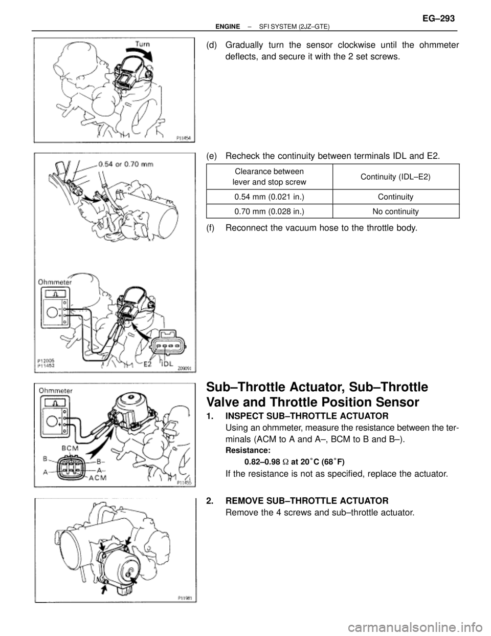
Sub±Throttle Actuator, Sub±Throttle
Valve and Throttle Position Sensor
1. INSPECT SUB±THROTTLE ACTUATOR
Using an ohmmeter, measure the resistance between the ter-
minals (ACM to A and A±, BCM to B and B±).
Resistance:
0.82±0.98 � at 20°C (68°F)
If the resistance is not as specified, replace the actuator.
2. REMOVE SUB±THROTTLE ACTUATOR
Remove the 4 screws and sub±throttle actuator.
± ENGINESFI SYSTEM (2JZ±GTE)EG±293
Page 1584 of 2543

3. INSPECT SUB±THROTTLE VALVE
Check that there is no clearance between the throttle stop
screw and throttle valve gear when the subthrottle valve is ful-
ly closed.
4. INSPECT SUB±THROTTLE POSITION SENSOR
(a) Set the sub±throttle valve to fully closed position.
(b) Insert a 0.41 mm (0.016 in.) or 0.48 mm (0.019 in.) feeler
gauge between the throttle stop screw and throttle valve
gear.
(c) Using an ohmmeter, measure the resistance between
terminals.
�������� �
������� ��������Clearance between
lever and stop screw�������� �
������� ��������Between terminals
�������� �
������� ��������Resistance
�������� ��������0 mm (0 in.)�������� ��������VTA±E2�������� ��������0.3±6.3 k��������� ��������0.41 mm (0.016 in.)�������� ��������IDL±E2�������� ��������0.5 k� or less�������� ��������0.48 mm (0.019 in.)�������� ��������IDL±E2�������� ��������Infinity�������� �
������� ��������Throttle valve fully
open�������� �
������� ��������VTA±E2
�������� �
������� ��������2.0±10.8 k�
�������� ��������±�������� ��������VC±E2�������� ��������3.5±6.5 k�
5. IF NECESSARY, ADJUST SUB±THROTTLE POSITION
SENSOR
(a) Loosen the 2 set screws of the sensor.
(b) Set the sub±throttle valve to fully closed position.
(c) Insert a 0.45 mm (0.018 in.) feeler gauge, between the
throttle stop screw and throttle valve gear. EG±294
± ENGINESFI SYSTEM (2JZ±GTE)
Page 1585 of 2543
(d) Connect the tester probe of an ohmmeter to the terminals IDL
and E2 of the sensor.
(e) Gradually turn the sensor clockwise until the ohmmeter
deflects, and secure it with the 2 set screws.
(f) Recheck the continuity between terminals IDL and E2.
����������� �
���������� �����������
Clearance between
lever and stop screw������������ �
����������� ������������Continuity (IDL±E2)
����������� �����������0.41 mm (0.016 in.)������������ ������������Continuity
����������� �����������0.48 mm (0.019 in.)������������ ������������No continuity
6. REINSTALL SUB±THROTTLE ACTUATOR
Install the sub±throttle actuator with the 4 screws.
± ENGINESFI SYSTEM (2JZ±GTE)EG±295
Page 1601 of 2543
C. Inspect VSV operation
(a) Check that air does not flow from port E to F.
(b) Apply battery voltage across the terminals.
(c) Check that air flows from port E to F.
If operation is not as specified, replace the VSV.
3. REINSTALL VSV
ENGINE COOLANT TEMPERATURE
(ECT) SENSOR
COMPONENTS FOR REMOVAL AND
INSTALLATION
± ENGINESFI SYSTEM (2JZ±GTE)EG±311
Page 1602 of 2543
ECT SENSOR INSPECTION
1. DRAIN ENGINE COOLANT
2. REMOVE ECT SENSOR
(a) Disconnect the ECT sensor connector.
(b) Using SST, remove the ECT sensor and gasket.
SST 09205±76030
3. INSPECT ECT SENSOR
Using an ohmmeter, measure the resistance between the ter-
minals.
Resistance:
Refer to the graph
If the resistance is not as specified, replace the ECT sensor.
4. REINSTALL ECT SENSOR
(a) Install a new gasket to the ECT sensor.
(b) Using SST, install the ECT sensor.
SST 09205±76030
(c) Connect the ECT sensor connector.
5. REFILL WITH ENGINE COOLANT EG±312
± ENGINESFI SYSTEM (2JZ±GTE)
Page 1603 of 2543
EGR GAS TEMPERATURE SENSOR
COMPONENTS FOR REMOVAL AND
INSTALLATION
EGR GAS TEMPERATURE SENSOR
INSPECTION
1. REMOVE EGR GAS TEMPERATURE SENSOR
2. INSPECT EGR GAS TEMPERATURE SENSOR
Using an ohmmeter, measure the resistance between the ter-
minals.
Resistance:
At 50°C (112°F)
64±97 k�
At 100°C (212°F)
11±16 k �
At 150°C (302°F)
2±4 k �
If the resistance is not as specified, replace the sensor.
Torque: 20 NVm (200 kgfVcm, 14 ftVlbf)
3. REINSTALL EGR GAS TEMPERATURE SENSOR
± ENGINESFI SYSTEM (2JZ±GTE)EG±313
Page 1604 of 2543
TURBO PRESSURE SENSOR
COMPONENTS FOR REMOVAL AND
INSTALLATION
TURBO PRESSURE SENSOR
INSPECTION
1. INSPECT POWER SOURCE VOLTAGE OF TURBO
PRESSURE SENSOR
(a) Disconnect the turbo pressure sensor connector.
(b) Turn the ignition switch ON.
(c) Using a voltmeter, measure the voltage between connector
terminals VC and E2 of the wiring harness side.
Voltage:
4.5±5.5 V
(d) Turn the ignition switch OFF.
(e) Reconnect the turbo pressure sensor connector. EG±314
± ENGINESFI SYSTEM (2JZ±GTE)
Page 1605 of 2543
 Disconnect the ECM from the ECU bracket.
(See steps 1 to 4 in ECM)
(b) Install SST (check harness) between the ECM and wiring
connectors.
(See st")
2. INSPECT SUPPLY POWER OF TURBO PRESSURE
SENSOR
(a) Disconnect the ECM from the ECU bracket.
(See steps 1 to 4 in ECM)
(b) Install SST (check harness) between the ECM and wiring
connectors.
(See standard value of ECM terminals in Engine Trouble-
shooting)
SST 09990±01000
(c) Turn the ignition switch ON.
(d) Disconnect the vacuum hose from the turbo pressure sensor.
(e) Connect a voltmeter to terminals PIM and E2 of the ECM, and
measure the output voltage under ambient atmospheric
pressure.
(f) Apply vacuum to the turbo pressure sensor in 13.3 kPa (100
mmHg, 3.94 in.Hg) segments to 66.7 kPa (500 mmHg, 19.69
in.Hg).
(g) Measure the voltage drop from step (c) above for each
segment.
Voltage drop
������ �
����� �
����� �
����� �
����� ������
Applied
Vacuum
kPa
(mmHg)
(in.Hg.)���� �
��� �
��� �
��� �
��� ����
13.3
(100)
(3.94)
���� �
��� �
��� �
��� �
��� ����
26.7
(200)
(7.87)
���� �
��� �
��� �
��� �
��� ����
40.0
(300)
(11.81)
���� �
��� �
��� �
��� �
��� ����
53.3
(400)
(15.75)
���� �
��� �
��� �
��� �
��� ����
66.7
(500)
(19.69)
������ �
����� ������
Voltage
drop V���� �
��� ����
0.15±
0.35���� �
��� ����
0.4±
0.6���� �
��� ����
0.65±
0.85���� �
��� ����
0.9±
1.1���� �
��� ����
1.15±
1.35
(h) Remove the SST.
SST 09990±01000
(i) Reinstall the ECM. (See steps 6 to 9 in ECM)
(j) Reconnect the vacuum hose to the turbo pressure sensor.
± ENGINESFI SYSTEM (2JZ±GTE)EG±315
 Connect the tester probe of an ohmmeter to the terminals IDL
and E2 of the sensor.
(e) Gradually turn the sensor clockwise until the ohmmeter
deflects, and secure it with the 2 set screws.
(f)")
 Check that air does not flow from port E to F.
(b) Apply battery voltage across the terminals.
(c) Check that air flows from port E to F.
If operation is not as specif")
 Disconnect the ECT sensor connector.
(b) Using SST, remove the ECT sensor and gasket.
SST 09205±76030
3. INSPECT ECT SENSOR")

 Disconnect the turbo pressure sensor connec")