Page 1714 of 2543
COMPONENTS
FRONT AIRBAG SENSOR REMOVAL
AND INSTALLATION
NOTICE:
wIf the wiring connector of the SRS is disconnected
with the ignition switch at ON or ACC, diagnostic
trouble codes will be recorded.
wNever use SRS parts from another vehicle. When
replacing parts, replace with new parts.
wNever reuse the sensor involved in a collision when
the SRS has deployed.
wNever repair a sensor in order to reuse it.
± SUPPLEMENTAL RESTRAINT SYSTEMFRONT AIRBAG SENSORRS±31
Page 1715 of 2543
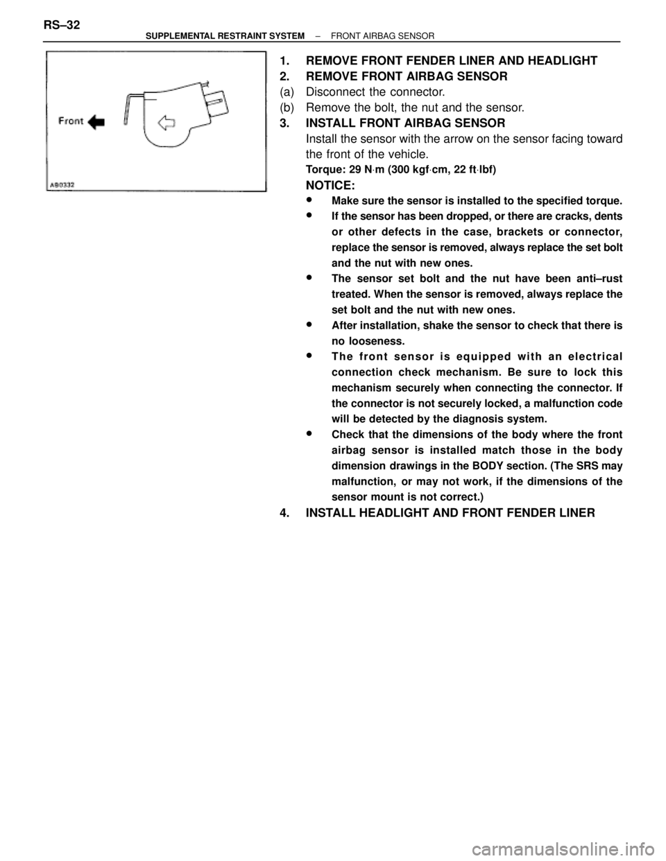
1. REMOVE FRONT FENDER LINER AND HEADLIGHT
2. REMOVE FRONT AIRBAG SENSOR
(a) Disconnect the connector.
(b) Remove the bolt, the nut and the sensor.
3. INSTALL FRONT AIRBAG SENSOR
Install the sensor with the arrow on the sensor facing toward
the front of the vehicle.
Torque: 29 NVm (300 kgfVcm, 22 ftVlbf)
NOTICE:
wMake sure the sensor is installed to the specified torque.
wIf the sensor has been dropped, or there are cracks, dents
or other defects in the case, brackets or connector,
replace the sensor is removed, always replace the set bolt
and the nut with new ones.
wThe sensor set bolt and the nut have been anti±rust
treated. When the sensor is removed, always replace the
set bolt and the nut with new ones.
wAfter installation, shake the sensor to check that there is
no looseness.
wThe front sensor is equipped with an electrical
connection check mechanism. Be sure to lock this
mechanism securely when connecting the connector. If
the connector is not securely locked, a malfunction code
will be detected by the diagnosis system.
wCheck that the dimensions of the body where the front
airbag sensor is installed match those in the body
dimension drawings in the BODY section. (The SRS may
malfunction, or may not work, if the dimensions of the
sensor mount is not correct.)
4. INSTALL HEADLIGHT AND FRONT FENDER LINER RS±32
± SUPPLEMENTAL RESTRAINT SYSTEMFRONT AIRBAG SENSOR
Page 1716 of 2543
CENTER AIRBAG SENSOR
ASSEMBLY
INSPECTION ITEMS
1. VEHICLES NOT INVOLVED IN A COLLISION
Do a diagnostic system check. (See page RS±44)
2. VEHICLES INVOLVED IN A COLLISION
IF THE SRS IS NOT DEPLOYED
Do a diagnostic system check.
(See page RS±44)
IF THE SRS IS DEPLOYED
Replace the center airbag sensor assembly.
REPLACEMENT REQUIREMENTS
In the following cases, replace the center airbag sensor as-
sembly.
wIf the SRS has been deployed in a collision.
wIf the center airbag sensor assembly has been found to
be faulty in troubleshooting.
wIf the center airbag sensor assembly has been dropped.
NOTICE: For replacement of the center airbag sensor as-
sembly, see page RS±34, ºCENTER AIRBAG SENSOR
ASSEMBLY REMOVAL AND INSTALLATIONº and be sure
to follow the correct procedure.
± SUPPLEMENTAL RESTRAINT SYSTEMCENTER AIRBAG SENSOR ASSEMBLYRS±33
Page 1717 of 2543
COMPONENTS
CENTER AIRBAG SENSOR ASSEMBLY
REMOVAL AND INSTALLATION
NOTICE:
wDo not open the cover or the case of the ECU and various
computers unless absolutely necessary.
(If the IC terminals are touched, the IC may be destroyed
by static electricity.)
RS±34± SUPPLEMENTAL RESTRAINT SYSTEMCENTER AIRBAG SENSOR ASSEMBLY
Page 1718 of 2543
wNever use SRS parts from another vehicle. When
replacing parts, replace with new parts.
wNever reuse the center airbag sensor assembly involved
in a collision when the airbag has deployed.
wNever repair a sensor in order to reuse it.
1. REMOVE CONSOLE PANEL UPPER AND CONSOLE BOX
(See page BO±44)
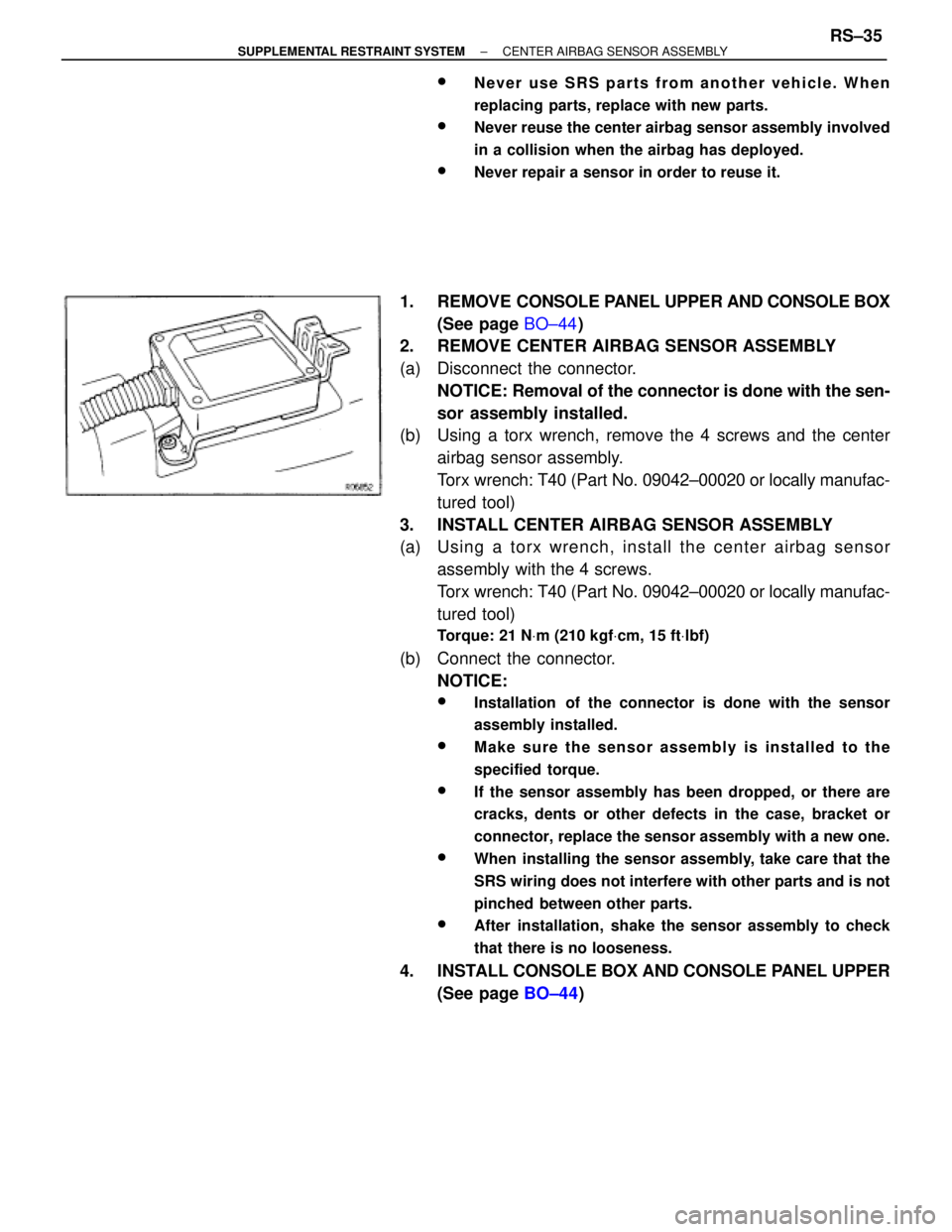
2. REMOVE CENTER AIRBAG SENSOR ASSEMBLY
(a) Disconnect the connector.
NOTICE: Removal of the connector is done with the sen-
sor assembly installed.
(b) Using a torx wrench, remove the 4 screws and the center
airbag sensor assembly.
Torx wrench: T40 (Part No. 09042±00020 or locally manufac-
tured tool)
3. INSTALL CENTER AIRBAG SENSOR ASSEMBLY
(a) Usin g a to rx wre n ch , in sta ll th e ce n te r airb a g se n so r
assembly with the 4 screws.
Torx wrench: T40 (Part No. 09042±00020 or locally manufac-
tured tool)
Torque: 21 NVm (210 kgfVcm, 15 ftVlbf)
(b) Connect the connector.
NOTICE:
wInstallation of the connector is done with the sensor
assembly installed.
wMake sure the sensor assembly is installed to the
specified torque.
wIf the sensor assembly has been dropped, or there are
cracks, dents or other defects in the case, bracket or
connector, replace the sensor assembly with a new one.
wWhen installing the sensor assembly, take care that the
SRS wiring does not interfere with other parts and is not
pinched between other parts.
wAfter installation, shake the sensor assembly to check
that there is no looseness.
4. INSTALL CONSOLE BOX AND CONSOLE PANEL UPPER
(See page BO±44)
± SUPPLEMENTAL RESTRAINT SYSTEMCENTER AIRBAG SENSOR ASSEMBLYRS±35
Page 1720 of 2543
REPLACEMENT REQUIREMENTS
In the following cases, replace the wire harness or connector.
wIf any part of the SRS wire harness or any connector has
been found to be faulty in troubleshooting.
wIf any part of the SRS wire harness or any connector has
been found to be faulty during the check in items 2±(b)
or (c).
NOTICE:
wIf the wire harness used in the SRS is damaged, replace
the whole wire harness assembly.
wWhen the connector to the front airbag sensors can be
repaired alone (when there is no damage to the wire
harness), use the repair wire specially designed for the
purpose.
REPAIR WIRE FOR FRONT AIRBAG
SENSOR REPLACEMENT
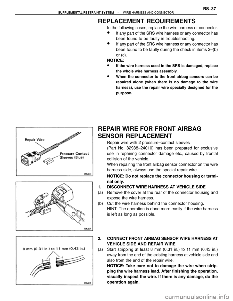
Repair wire with 2 pressure±contact sleeves
(Part No. 82988±24010) has been prepared for exclusive
use in repairing connector damage etc., caused by frontal
collision of the vehicle.
When repairing the front airbag sensor connector on the wire
harness side, always use the special repair wire.
NOTICE: Do not replace the connector housing or termi-
nal only.
1. DISCONNECT WIRE HARNESS AT VEHICLE SIDE
(a) Remove the cover at the rear of the connector housing and
expose the wire harness.
(b) Cut the wire harness behind the connector housing.
HINT: The operation is done more easily if the wire harness
is left as long as possible.
2. CONNECT FRONT AIRBAG SENSOR WIRE HARNESS AT
VEHICLE SIDE AND REPAIR WIRE
(a) Start stripping at least 8 mm (0.31 in.) to 11 mm (0.43 in.)
away from the end of the existing harness at vehicle side and
also from the end of the repair wire.
NOTICE: Take care not to damage the wire when strip-
ping the wire harness lead. After finishing the operation,
visually inspect the wire. If there is any damage, do the
operation again.
± SUPPLEMENTAL RESTRAINT SYSTEMWIRE HARNESS AND CONNECTORRS±37
Page 1727 of 2543
DIAGNOSIS INSPECTION
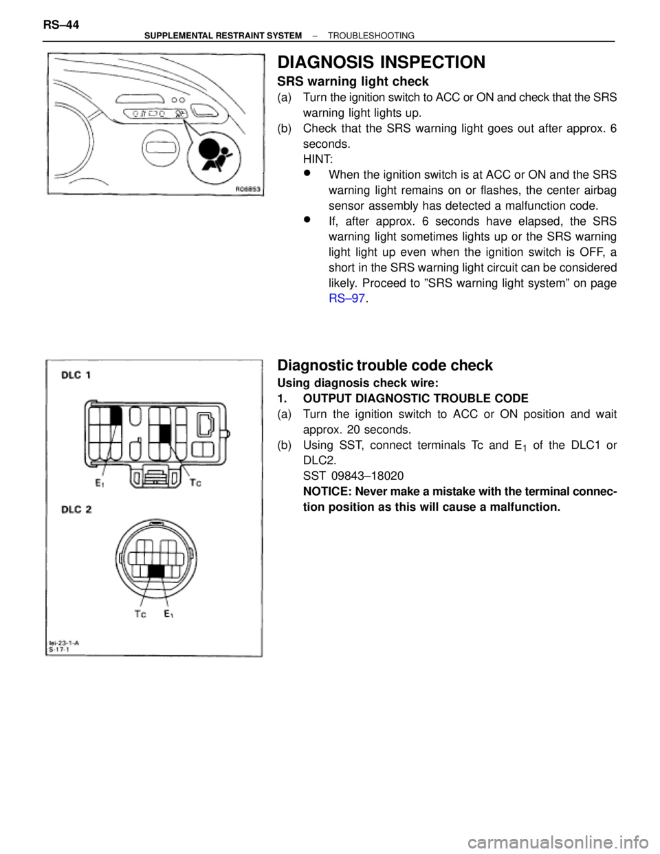
SRS warning light check
(a) Turn the ignition switch to ACC or ON and check that the SRS
warning light lights up.
(b) Check that the SRS warning light goes out after approx. 6
seconds.
HINT:
wWhen the ignition switch is at ACC or ON and the SRS
warning light remains on or flashes, the center airbag
sensor assembly has detected a malfunction code.
wIf, after approx. 6 seconds have elapsed, the SRS
warning light sometimes lights up or the SRS warning
light light up even when the ignition switch is OFF, a
short in the SRS warning light circuit can be considered
likely. Proceed to ºSRS warning light systemº on page
RS±97.
Diagnostic trouble code check
Using diagnosis check wire:
1. OUTPUT DIAGNOSTIC TROUBLE CODE
(a) Turn the ignition switch to ACC or ON position and wait
approx. 20 seconds.
(b) Using SST, connect terminals Tc and E
1 of the DLC1 or
DLC2.
SST 09843±18020
NOTICE: Never make a mistake with the terminal connec-
tion position as this will cause a malfunction. RS±44
± SUPPLEMENTAL RESTRAINT SYSTEMTROUBLESHOOTING
Page 1729 of 2543
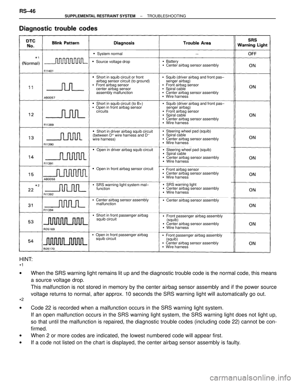
�System normal
�Source voltage drop
�Short in squib circuit or front
airbag sensor circuit (to ground)
�Front airbag sensor
center airbag sensor
assembly malfunction
�Short in squib circuit (to B+)
�Open in front airbag sensor
circuits
�Short in driver airbag squib circuit
(between D+ wire harness and D±
wire harness)
�Open in driver airbag squib circuit
�Open in front airbag sensor circuit
�SRS warning light system mal±
function
�Center airbag sensor assembly
malfunction
�Short in front passenger airbag
squib circuit
�Open in front passenger airbag
squib circuit
�Battery
�Center airbag sensor assembly
�Squib (driver airbag and front pas±
senger airbag)
�Front airbag sensor
�Spiral cable
�Center airbag sensor assembly
�Wire harness
�Squib (driver airbag and front pas±
senger airbag)
�Front airbag sensor
�Spiral cable
�Center airbag sensor assembly
�Wire harness
�Steering wheel pad (squib)
�Spiral cable
�Center airbag sensor assembly
�Wire harness
�Steering wheel pad (squib)
�Spiral cable
�Center airbag sensor assembly
�Wire harness
�Front airbag sensor
�Center airbag sensor assembly
�Wire harness
�SRS warning light
�Center airbag sensor assembly
�Wire harness
�Center airbag sensor assembly
�Front passenger airbag assembly
(squib)
�Center airbag sensor assembly
�Wire harness
�Front passenger airbag assembly
(squib)
�Center airbag sensor assembly
�Wire harness
HINT:
*
1
wWhen the SRS warning light remains lit up and the diagnostic trouble code is the normal code, this means
a source voltage drop.
This malfunction is not stored in memory by the center airbag sensor assembly and if the power source
voltage returns to normal, after approx. 10 seconds the SRS warning light will automatically go out.
*
2
wCode 22 is recorded when a malfunction occurs in the SRS warning light system.
If an open malfunction occurs in the SRS warning light system, the SRS warning light does not light up,
so that until the malfunction is repaired, the diagnostic trouble codes (including code 22) cannot be con-
firmed.
wWhen 2 or more codes are indicated, the lowest numbered code will appear first.
wIf a code not listed on the chart is displayed, the center airbag sensor assembly is faulty. RS±46
± SUPPLEMENTAL RESTRAINT SYSTEMTROUBLESHOOTING