Page 1606 of 2543
KNOCK SENSOR
COMPONENTS FOR REMOVAL AND
INSTALLATION
EG±316± ENGINESFI SYSTEM (2JZ±GTE)
Page 1607 of 2543
KNOCK SENSORS INSPECTION
1. REMOVE THROTTLE BODY
(See throttle body removal)
2. REMOVE STARTER
(See starter removal in Starting System)
3. REMOVE KNOCK SENSORS
(a) Disconnect the knock sensor connector.
(b) Using SST, remove the knock sensor.
SST 09816±30010
4. INSPECT KNOCK SENSORS
Using an ohmmeter, check that there is no continuity be-
tween the terminal and body.
If there is continuity, replace the sensor.
5. REINSTALL KNOCK SENSORS
(a) Using SST, install the knock sensor.
SST 09816±30010
Torque: 44 NVm (450 kgfVcm, 33 ftVlbf)
(b) Connect the knock sensor connector.
6. REINSTALL STARTER
(See starter installation in Starting System)
7. REINSTALL THROTTLE BODY
(See throttle body installation)
± ENGINESFI SYSTEM (2JZ±GTE)EG±317
Page 1608 of 2543
OXYGEN SENSOR
Main Heated Oxygen Sensor
COMPONENTS FOR REMOVAL AND
INSTALLATION
OXYGEN SENSOR INSPECTION
1. WARM UP ENGINE
Allow the engine to warm up to normal operating tempera-
ture.
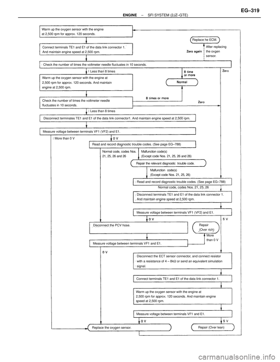
2. INSPECT FEEDBACK VOLTAGE
Connect the positive (+) tester probe of a voltmeter to termi-
nal VF1 of the DLC1, and negative (±) tester probe to terminal
E1. Do the test as described on the next page.
HINT: Use SST when connecting between terminals TE1 and
E1 of the DLC1.
SST 09843±18020 EG±318
± ENGINESFI SYSTEM (2JZ±GTE)
Page 1609 of 2543

(See page EG±788)
(See page EG±788)
Warm up the oxygen sensor with the engine
at 2,500 rpm for approx. 120 seconds.
Connect terminals TE1 and E1 of the data link connector 1.
And maintain engine speed at 2,500 rpm.
Check the number of times the voltmeter needle fluctuates in 10 seconds.
Less than 8 times
Warm up the oxygen sensor with the engine at
2,500 rpm for approx. 120 seconds. And maintain
engine at 2,500 rpm.
Check the number of times the voltmeter needle
fluctuates in 10 seconds.
Less than 8 times
Disconnect terminates TE1 and E1 of the data link connector1. And maintain engine speed at 2,500 rpm.
Measure voltage between terminals VF1 (VF2) and E1.
More than 0 V
Read and record diagnostic trouble codes. (See page EG±788)
Normal code, codes Nos.
21, 25, 26 and 26Malfunction code(s)
(Except code Nos. 21, 25, 26 and 26)
Repair the relevant diagnostic trouble code.
Malfunction code(s)
(Except code Nos. 21, 25, 26)
Read and record diagnostic trouble codes. (See page EG±788)
Normal code, codes Nos. 21, 25, 26
Disconnect terminals TE1 and E1 of the data link connector 1.
And maintain engine speed at 2,500 rpm.
Measure voltage between terminals VF1 (VF2) and E1.
Repair
(Over rich)
More
than 0 V
Disconnect the PCV hose.
Measure voltage between terminals VF1 and E1.
Disconnect the ECT sensor connector, and connect resistor
with a resistance of 4 ± 8k� or send an equivalent simulation
signal.
Connect terminals TE1 and E1 of the data link connector 1.
Warm up the oxygen sensor with the engine at
2,500 rpm for approx. 120 seconds. And maintain engine
speed at 2,500 rpm.
Measure voltage between terminals VF1 and E1.
Repair (Over lean)Replace the oxygen sensor.
After replacing
the oxgen
sensor.
Replace he ECM.
± ENGINESFI SYSTEM (2JZ±GTE)EG±319
Page 1610 of 2543
3. INSPECT HEATER RESISTANCE OF MAIN HEATED
OXYGEN SENSOR
(a) Disconnect the oxygen sensor connector.
(b) Using an ohmmeter, measure the resistance between the
terminals +B and HT.
Resistance:
At 20°C (68°F) 11±16 �
If the resistance is not as specified, replace the sensor.
Torque: 20 NVm (200 kgfVcm, 14 ftVlbf)
(c) Reconnect the oxygen sensor connector. EG±320
± ENGINESFI SYSTEM (2JZ±GTE)
Page 1611 of 2543
Sub Heated Oxygen Sensor
COMPONENTS FOR REMOVAL AND
INSTALLATION
± ENGINESFI SYSTEM (2JZ±GTE)EG±321
Page 1612 of 2543
OXYGEN SENSOR INSPECTION
1. INSPECT OPERATION OF SUB HEATED OXYGEN
SENSOR
(See circuit inspection in Engine Troubleshooting)
2. INSPECT HEATER RESISTANCE OF SUB HEATED
OXYGEN SENSOR
(a) Remove the driver's seat.
(b) Take out the console box side of the floor carpet.
(c) Disconnect the oxygen sensor connector.
(d) Using an ohmmeter, measure the resistance between the
terminals +B and HT.
Resistance:
At 20°C (68°F) 11±16 �
If the resistance is not as specified, replace the sensor.
Torque: 20 NVm (200 kgfVcm, 14 ftVlbf)
(e) Reconnect the oxygen sensor connector.
(f) Reinstall the floor carpet.
(g) Reinstall the driver's seat. EG±322
± ENGINESFI SYSTEM (2JZ±GTE)
Page 1617 of 2543

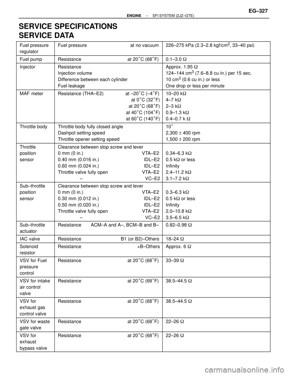
SERVICE SPECIFICATIONS
SERVICE DATA
������ �
����� ������Fuel pressure
regulator���������������� �
��������������� ����������������Fuel pressure at no vacuum���������������� �
��������������� ����������������226±275 kPa (2.3±2.8 kgf/cm2, 33±40 psi)
������ ������Fuel pump���������������� ����������������Resistance at 20°C (68°F)���������������� ����������������0.1±3.0 ������� �
����� �
����� �
����� ������
Injector���������������� �
��������������� �
��������������� �
��������������� ����������������
Resistance
Injection volume
Difference between each cylinder
Fuel leakage���������������� �
��������������� �
��������������� �
��������������� ����������������
Approx. 1.95 �
124±144 cm3 (7.6±8.8 cu in.) per 15 sec.
10 cm
3 (0.6 cu in.) or less
One drop or less per minute
������ �
����� �
����� �
����� ������
MAF meter���������������� �
��������������� �
��������������� �
��������������� ����������������
Resistance (THA±E2) at ±20°C (±4°F)
at 0°C (32°F)
at 20°C (68°F)
at 40°C (104°F)
at 60°C (140°F)���������������� �
��������������� �
��������������� �
��������������� ����������������
10±20 k�
4±7 k�
2±3 k�
0.9±1.3 k�
0.4±0.7 k �
������ �
����� �
����� ������
Throttle body���������������� �
��������������� �
��������������� ����������������
Throttle body fully closed angle
Dashpot setting speed
Throttle opener setting speed���������������� �
��������������� �
��������������� ����������������
10°
2,300 + 400 rpm
1,500 + 200 rpm
������ �
����� �
����� �
����� �
����� �
����� ������
Throttle
position
sensor���������������� �
��������������� �
��������������� �
��������������� �
��������������� �
��������������� ����������������
Clearance between stop screw and lever
0 mm (0 in.) VTA±E2
0.40 mm (0.016 in.) IDL±E2
0.60 mm (0.024 in.) IDL±E2
Throttle valve fully open VTA±E2
± VC±E2���������������� �
��������������� �
��������������� �
��������������� �
��������������� �
��������������� ����������������
0.34±6.3 k�
0.5 k� or less
Infinity
2.4±11.2 k�
3.1±7.2 k�
������ �
����� �
����� �
����� �
����� ������
Sub±throttle
position
sensor���������������� �
��������������� �
��������������� �
��������������� �
��������������� ����������������
Clearance between stop screw and lever
0 mm (0 in.) VTA±E2
0.30 mm (0.012 in.) IDL±E2
0.50 mm (0.020 in.) IDL±E2
Throttle valve fully open VTA±E2
± VC±E2���������������� �
��������������� �
��������������� �
��������������� �
��������������� ����������������
0.3±6.3 k�
0.5 k� or less
Infinity
2.0±10.8 k�
3.5±6.5 k�
������ �
����� ������
Sub±throttle
actuator���������������� �
��������������� ����������������
Resistance ACM±A and A±, BCM±B and B±���������������� �
��������������� ����������������
0.82±0.98 �
������ ������IAC valve���������������� ����������������Resistance B1 (or B2)±Others���������������� ����������������18±24 �
������ �
����� ������
Solenoid
resistor���������������� �
��������������� ����������������
Resistance +B±Others���������������� �
��������������� ����������������
Approx. 6 �
������ �
����� �
����� ������
VSV for Fuel
pressure
control���������������� �
��������������� �
��������������� ����������������
Resistance at 20°C (68°F)���������������� �
��������������� �
��������������� ����������������
33±39 �
������ �
����� ������
VSV for intake
air control
valve���������������� �
��������������� ����������������
Resistance at 20°C (68°F)���������������� �
��������������� ����������������
38.5±44.5 �
������ �
����� �
����� ������
VSV for
exhaust gas
control valve���������������� �
��������������� �
��������������� ����������������
Resistance at 20°C (68°F)���������������� �
��������������� �
��������������� ����������������
38.5±44.5 �
������ �
����� ������VSV for waste
gate valve���������������� �
��������������� ����������������Resistance at 20°C (68°F)���������������� �
��������������� ����������������22±26 �
������ �
����� �
����� ������
VSV for
exhaust
bypass valve���������������� �
��������������� �
��������������� ����������������
Resistance at 20°C (68°F)���������������� �
��������������� �
��������������� ����������������
22±26 �
± ENGINESFI SYSTEM (2JZ±GTE)EG±327