Page 1461 of 2543
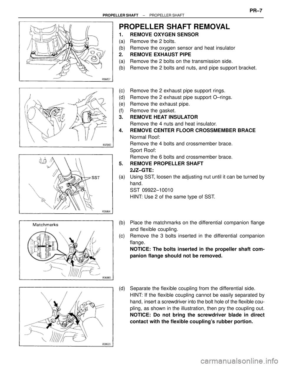
PROPELLER SHAFT REMOVAL
1. REMOVE OXYGEN SENSOR
(a) Remove the 2 bolts.
(b) Remove the oxygen sensor and heat insulator
2. REMOVE EXHAUST PIPE
(a) Remove the 2 bolts on the transmission side.
(b) Remove the 2 bolts and nuts, and pipe support bracket.
(c) Remove the 2 exhaust pipe support rings.
(d) Remove the 2 exhaust pipe support O±rings.
(e) Remove the exhaust pipe.
(f) Remove the gasket.
3. REMOVE HEAT INSULATOR
Remove the 4 nuts and heat insulator.
4. REMOVE CENTER FLOOR CROSSMEMBER BRACE
Normal Roof:
Remove the 4 bolts and crossmember brace.
Sport Roof:
Remove the 6 bolts and crossmember brace.
5. REMOVE PROPELLER SHAFT
2JZ±GTE:
(a) Using SST, loosen the adjusting nut until it can be turned by
hand.
SST 09922±10010
HINT: Use 2 of the same type of SST.
(b) Place the matchmarks on the differential companion flange
and flexible coupling.
(c) Remove the 3 bolts inserted in the differential companion
flange.
NOTICE: The bolts inserted in the propeller shaft com-
panion flange should not be removed.
(d) Separate the flexible coupling from the differential side.
HINT: If the flexible coupling cannot be easily separated by
hand, insert a screwdriver into the bolt hole of the flexible cou-
pling, as shown in the illustration, then pry the coupling out.
NOTICE: Do not bring the screwdriver blade in direct
contact with the flexible coupling's rubber portion.
± PROPELLER SHAFTPROPELLER SHAFTPR±7
Page 1470 of 2543
2. INSPECT PROPELLER SHAFT JOINT ANGLE
(See page PR±17)
NOTICE: The joint angle should be checked when the
propeller shaft is removed and installed.
3. INSTALL CROSSMEMBER BRACE
Normal Roof:
Install the center floor crossmember brace and torque the 4
bolts.
Torque: 13 NVm (130 kgfVcm, 8 ftVlbf)
Sport Roof:
Install the center floor crossmember brace and torque the 6
bolts.
Torque: 13 NVm (130 kgfVcm, 8 ftVlbf)
4. INSTALL HEAT INSULATOR
Install the heat insulator and torque the 4 nuts.
Torque: 5.4 NVm (55 kgfVcm, 48 in.Vlbf)
5. INSTALL EXHAUST PIPE
(a) Install a new gasket.
(b) Insert the exhaust pipe.
(c) Install the exhaust pipe to the 2 exhaust pipe support rings.
(d) Install the exhaust pipe to the 2 exhaust pipe support
O±rings.
(e) Temporary install the pipe support bracket to the
transmission with 2 bolts.
(f) Install the exhaust pipe with the 2 bolts and new 2 nuts.
Torque: 58 NVm (590 kgfVcm, 43 ftVlbf)
(g) Torque the 2 bolts.
Torque: 37 NVm (380 kgfVcm, 27 ftVlbf)
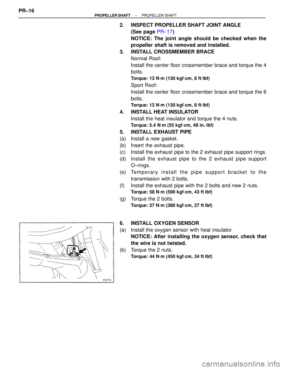
6. INSTALL OXYGEN SENSOR
(a) Install the oxygen sensor with heat insulator.
NOTICE: After installing the oxygen sensor, check that
the wire is not twisted.
(b) Torque the 2 nuts.
Torque: 44 NVm (450 kgfVcm, 34 ftVlbf)
PR±16± PROPELLER SHAFTPROPELLER SHAFT
Page 1476 of 2543
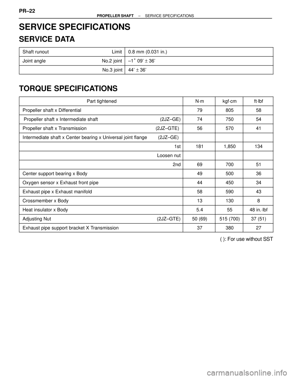
SERVICE SPECIFICATIONS
SERVICE DATA
��������������� ���������������Shaft runout Limit��������������������� ���������������������0.8 mm (0.031 in.)
��������������� ���������������Joint angle No.2 joint��������������������� ���������������������±1° 09' + 36'��������������� �
��������������
���������������
No.3 joint
��������������������� �
�������������������� ���������������������44' +36'
TORQUE SPECIFICATIONS
����������������������� �����������������������Part tightened������ ������NVm����� �����kgfVcm����� �����ftVlbf
����������������������� �����������������������Propeller shaft x Differential������ ������79����� �����805����� �����58
����������������������� �����������������������Propeller shaft x Intermediate shaft (2JZ±GE)������ ������74����� �����750����� �����54����������������������� �
���������������������� �����������������������Propeller shaft x Transmission (2JZ±GTE)
������ �
����� ������56
����� �
���� �����570
����� �
���� �����41
����������������������� �����������������������Intermediate shaft x Center bearing x Universal joint flange (2JZ±GE)������ ����������� ���������� �����
����������������������� �����������������������1st������ ������181����� �����1,850����� �����134
����������������������� �����������������������Loosen nut������ ����������� ���������� �����
����������������������� �
���������������������� �����������������������2nd
������ �
����� ������69
����� �
���� �����700
����� �
���� �����51
����������������������� �����������������������Center support bearing x Body������ ������49����� �����500����� �����36
����������������������� �����������������������Oxygen sensor x Exhaust front pipe������ ������44����� �����450����� �����34
����������������������� �����������������������Exhaust pipe x Exhaust manifold������ ������58����� �����590����� �����43����������������������� �����������������������Crossmember x Body������ ������13����� �����130����� �����8����������������������� �
���������������������� �����������������������Heat insulator x Body
������ �
����� ������5.4
����� �
���� �����55
����� �
���� �����48 in.Vlbf
����������������������� �����������������������Adjusting Nut (2JZ±GTE)������ ������50 (69)����� �����515 (700)����� �����37 (51)
����������������������� �����������������������Exhaust pipe support bracket X Transmission������ ������37����� �����380����� �����27
( ): For use without SST PR±22
± PROPELLER SHAFTSERVICE SPECIFICATIONS
Page 1477 of 2543
09205±76030Cylinder Head Setting Bolt
Tightening Adaptor
09268±41045Injection Measuring Tool Set
(09268±41070)No.4 Union
(09268±41090)No.7 Union
(90405±09015)No.1 Union
09268±45012 EFI Fuel Pressure Gauge
ECT sensor
09612±24014 Steering Gear Housing Overhaul
Tool Set
(09617±24011) Steering Rack Wrench
09631±22020 Power Steering Hose Nut
14 x 17 mm Wrench Set
09808±14010Fuel Sender Gauge Tool Assy
09816±30010 Oil Pressure Switch Socket
09842±30070 Wiring ªFº EFI InspectionInjector
Knock sensor
Fuel line flare nut
Fuel pressure pulsation damper
SFI SYSTEM (2JZ±GE)
PREPARATION
SST (SPECIAL SERVICE TOOLS)
± ENGINESFI SYSTEM (2JZ±GE)EG±187
Page 1479 of 2543
PRECAUTION
1. Before working on the fuel system, disconnect the
negative (±) terminal cable from the battery.
HINT: Any diagnostic trouble code retained by the computer
will be erased when the negative (±) terminal cable is discon-
nected.
Therefore, if necessary, read the diagnosis before discon-
necting the negative (±) terminal cable from the battery.
2. Do not smoke or work near an open flame when working
on the fuel system.
3. Keep gasoline away from rubber or leather parts.
MAINTENANCE PRECAUTIONS
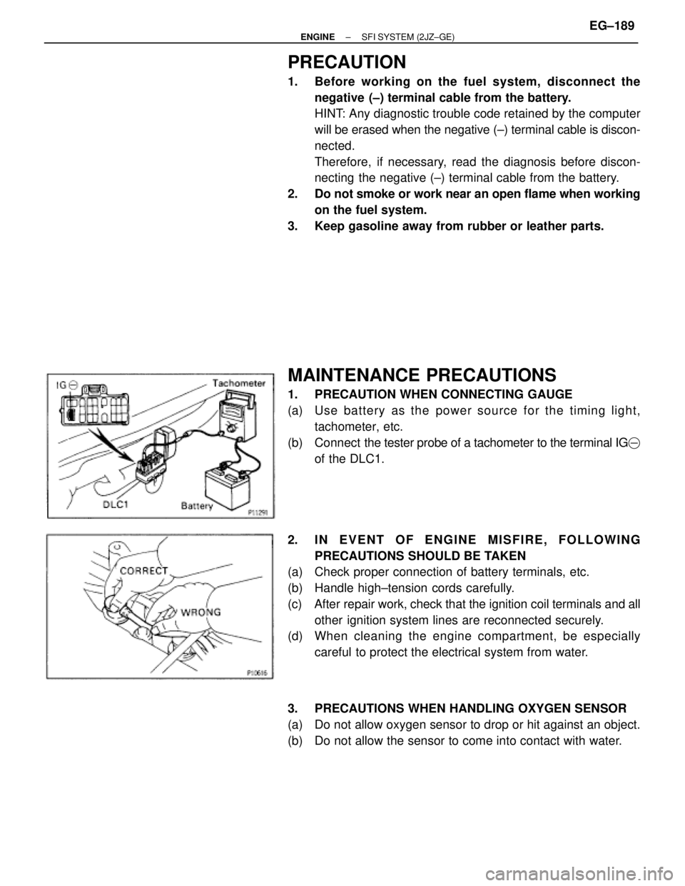
1. PRECAUTION WHEN CONNECTING GAUGE
(a) Use ba tte ry as th e po we r so u rce fo r th e timin g lig h t,
tachometer, etc.
(b) Connect the tester probe of a tachometer to the terminal IG�
of the DLC1.
2. IN EVENT OF ENGINE MISFIRE, FOLLOWING
PRECAUTIONS SHOULD BE TAKEN
(a) Check proper connection of battery terminals, etc.
(b) Handle high±tension cords carefully.
(c) After repair work, check that the ignition coil terminals and all
other ignition system lines are reconnected securely.
(d) When cleaning the engine compartment, be especially
careful to protect the electrical system from water.
3. PRECAUTIONS WHEN HANDLING OXYGEN SENSOR
(a) Do not allow oxygen sensor to drop or hit against an object.
(b) Do not allow the sensor to come into contact with water.
± ENGINESFI SYSTEM (2JZ±GE)EG±189
Page 1494 of 2543
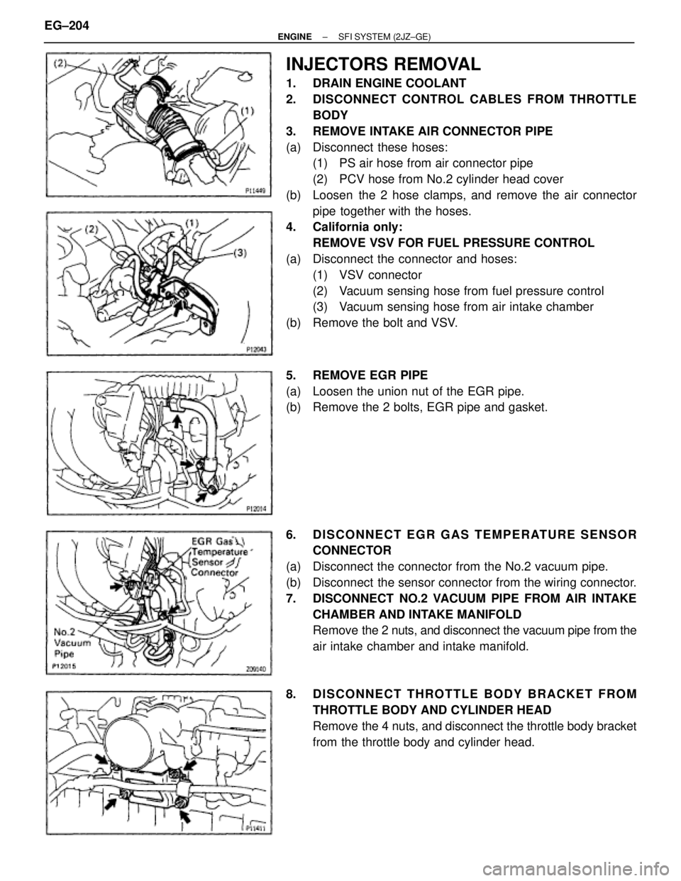
INJECTORS REMOVAL
1. DRAIN ENGINE COOLANT
2. DISCONNECT CONTROL CABLES FROM THROTTLE
BODY
3. REMOVE INTAKE AIR CONNECTOR PIPE
(a) Disconnect these hoses:
(1) PS air hose from air connector pipe
(2) PCV hose from No.2 cylinder head cover
(b) Loosen the 2 hose clamps, and remove the air connector
pipe together with the hoses.
4. California only:
REMOVE VSV FOR FUEL PRESSURE CONTROL
(a) Disconnect the connector and hoses:
(1) VSV connector
(2) Vacuum sensing hose from fuel pressure control
(3) Vacuum sensing hose from air intake chamber
(b) Remove the bolt and VSV.
5. REMOVE EGR PIPE
(a) Loosen the union nut of the EGR pipe.
(b) Remove the 2 bolts, EGR pipe and gasket.
6. DISCONNECT EGR GAS TEMPERATURE SENSOR
CONNECTOR
(a) Disconnect the connector from the No.2 vacuum pipe.
(b) Disconnect the sensor connector from the wiring connector.
7. DISCONNECT NO.2 VACUUM PIPE FROM AIR INTAKE
CHAMBER AND INTAKE MANIFOLD
Remove the 2 nuts, and disconnect the vacuum pipe from the
air intake chamber and intake manifold.
8. DISCONNECT THROTTLE BODY BRACKET FROM
THROTTLE BODY AND CYLINDER HEAD
Remove the 4 nuts, and disconnect the throttle body bracket
from the throttle body and cylinder head. EG±204
± ENGINESFI SYSTEM (2JZ±GE)
Page 1495 of 2543
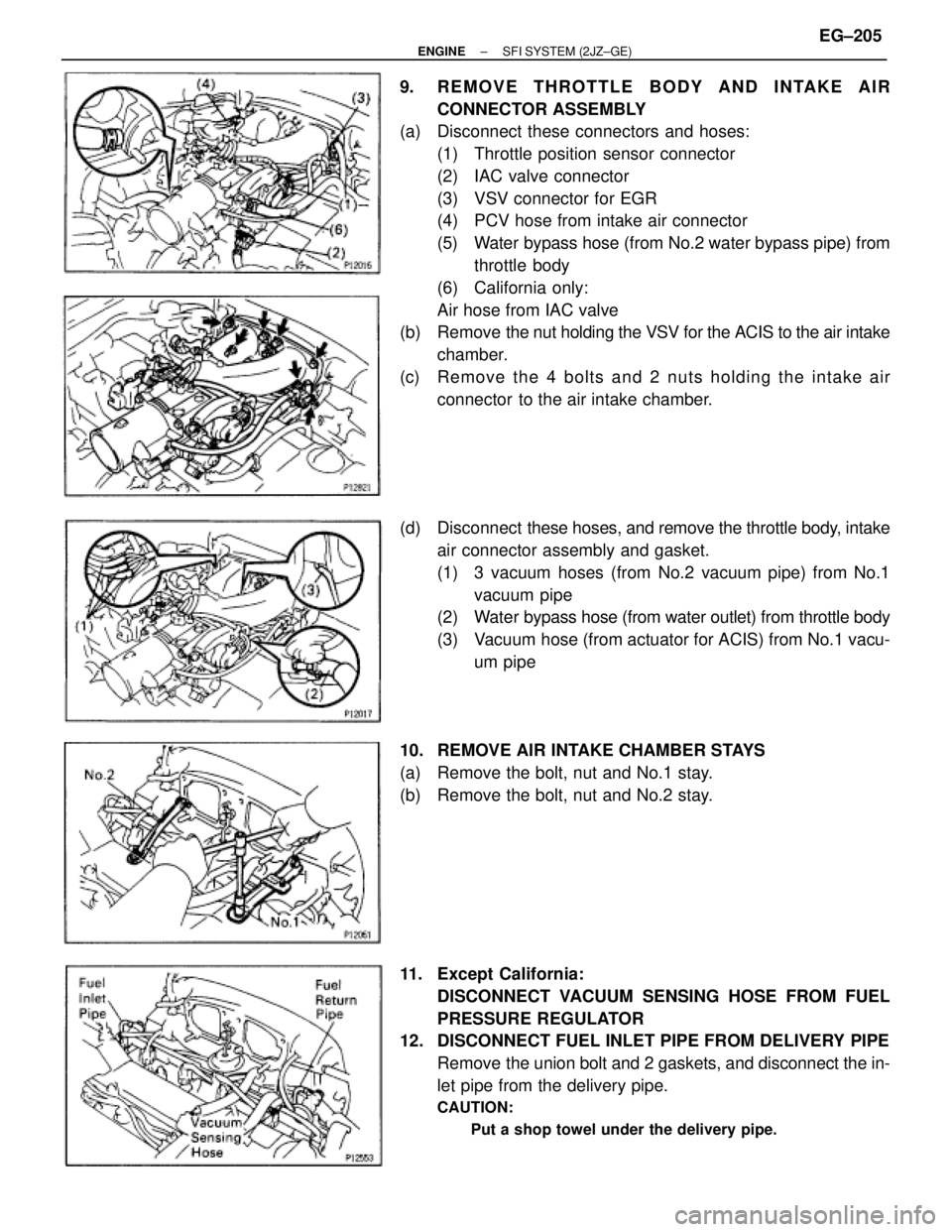
9. REMOVE THROTTLE BODY AND INTAKE AIR
CONNECTOR ASSEMBLY
(a) Disconnect these connectors and hoses:
(1) Throttle position sensor connector
(2) IAC valve connector
(3) VSV connector for EGR
(4) PCV hose from intake air connector
(5) Water bypass hose (from No.2 water bypass pipe) from
throttle body
(6) California only:
Air hose from IAC valve
(b) Remove the nut holding the VSV for the ACIS to the air intake
chamber.
(c) Remove the 4 bolts and 2 nuts holding the intake air
connector to the air intake chamber.
(d) Disconnect these hoses, and remove the throttle body, intake
air connector assembly and gasket.
(1) 3 vacuum hoses (from No.2 vacuum pipe) from No.1
vacuum pipe
(2) Water bypass hose (from water outlet) from throttle body
(3) Vacuum hose (from actuator for ACIS) from No.1 vacu-
um pipe
10. REMOVE AIR INTAKE CHAMBER STAYS
(a) Remove the bolt, nut and No.1 stay.
(b) Remove the bolt, nut and No.2 stay.
11. Except California:
DISCONNECT VACUUM SENSING HOSE FROM FUEL
PRESSURE REGULATOR
12. DISCONNECT FUEL INLET PIPE FROM DELIVERY PIPE
Remove the union bolt and 2 gaskets, and disconnect the in-
let pipe from the delivery pipe.
CAUTION:
� Put a shop towel under the delivery pipe.
± ENGINESFI SYSTEM (2JZ±GE)EG±205
Page 1502 of 2543
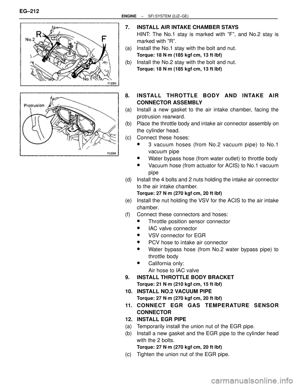
7. INSTALL AIR INTAKE CHAMBER STAYS
HINT: The No.1 stay is marked with ºFº, and No.2 stay is
marked with ºRº.
(a) Install the No.1 stay with the bolt and nut.
Torque: 18 NVm (185 kgfVcm, 13 ftVlbf)
(b) Install the No.2 stay with the bolt and nut.
Torque: 18 NVm (185 kgfVcm, 13 ftVlbf)
8. INSTALL THROTTLE BODY AND INTAKE AIR
CONNECTOR ASSEMBLY
(a) Install a new gasket to the air intake chamber, facing the
protrusion rearward.
(b) Place the throttle body and intake air connector assembly on
the cylinder head.
(c) Connect these hoses:
w3 vacuum hoses (from No.2 vacuum pipe) to No.1
vacuum pipe
wWater bypass hose (from water outlet) to throttle body
wVacuum hose (from actuator for ACIS) to No.1 vacuum
pipe
(d) Install the 4 bolts and 2 nuts holding the intake air connector
to the air intake chamber.
Torque: 27 NVm (270 kgfVcm, 20 ftVlbf)
(e) Install the nut holding the VSV for the ACIS to the air intake
chamber.
(f) Connect these connectors and hoses:
wThrottle position sensor connector
wIAC valve connector
wVSV connector for EGR
wPCV hose to intake air connector
wWater bypass hose (from No.2 water bypass pipe) to
throttle body
wCalifornia only:
Air hose to IAC valve
9. INSTALL THROTTLE BODY BRACKET
Torque: 21 NVm (210 kgfVcm, 15 ftVlbf)
10. INSTALL NO.2 VACUUM PIPE
Torque: 27 NVm (270 kgfVcm, 20 ftVlbf)
11. CONNECT EGR GAS TEMPERATURE SENSOR
CONNECTOR
12. INSTALL EGR PIPE
(a) Temporarily install the union nut of the EGR pipe.
(b) Install a new gasket and the EGR pipe to the cylinder head
with the 2 bolts.
Torque: 27 NVm (270 kgfVcm, 20 ftVlbf)
(c) Tighten the union nut of the EGR pipe. EG±212
± ENGINESFI SYSTEM (2JZ±GE)