Page 1699 of 2543
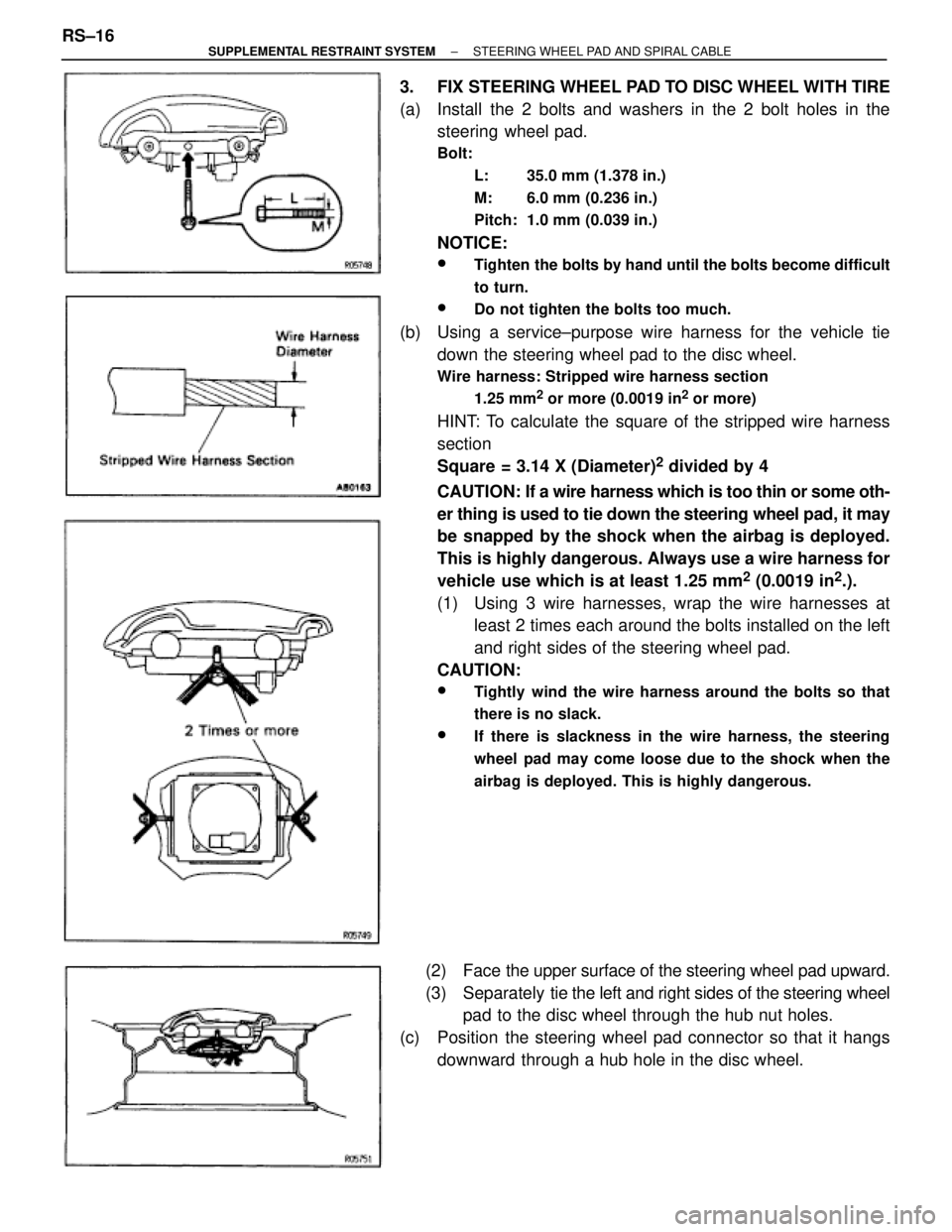
3. FIX STEERING WHEEL PAD TO DISC WHEEL WITH TIRE
(a) Install the 2 bolts and washers in the 2 bolt holes in the
steering wheel pad.
Bolt:
L: 35.0 mm (1.378 in.)
M: 6.0 mm (0.236 in.)
Pitch: 1.0 mm (0.039 in.)
NOTICE:
wTighten the bolts by hand until the bolts become difficult
to turn.
wDo not tighten the bolts too much.
(b) Using a service±purpose wire harness for the vehicle tie
down the steering wheel pad to the disc wheel.
Wire harness: Stripped wire harness section
1.25 mm
2 or more (0.0019 in2 or more)
HINT: To calculate the square of the stripped wire harness
section
Square = 3.14 X (Diameter)
2 divided by 4
CAUTION: If a wire harness which is too thin or some oth-
er thing is used to tie down the steering wheel pad, it may
be snapped by the shock when the airbag is deployed.
This is highly dangerous. Always use a wire harness for
vehicle use which is at least 1.25 mm
2 (0.0019 in2.).
(1) Using 3 wire harnesses, wrap the wire harnesses at
least 2 times each around the bolts installed on the left
and right sides of the steering wheel pad.
CAUTION:
wTightly wind the wire harness around the bolts so that
there is no slack.
wIf there is slackness in the wire harness, the steering
wheel pad may come loose due to the shock when the
airbag is deployed. This is highly dangerous.
(2) Face the upper surface of the steering wheel pad upward.
(3) Separately tie the left and right sides of the steering wheel
pad to the disc wheel through the hub nut holes.
(c) Position the steering wheel pad connector so that it hangs
downward through a hub hole in the disc wheel. RS±16
± SUPPLEMENTAL RESTRAINT SYSTEMSTEERING WHEEL PAD AND SPIRAL CABLE
Page 1700 of 2543
CAUTION:
wMake sure that the wire harness is tight. It is very
dangerous if looseness in the wire harness results in the
steering wheel pad coming free through the shock of the
airbag deploying.
wAlways tie down the steering wheel pad with the pad side
facing upward. It is very dangerous if the steering wheel
pad is tied down with the metal surface facing upward as
the wire harness will be cut by the shock of the airbag
deploying and the steering wheel pad will be thrown into
the air.
HINT: The disc wheel will be marked by airbag deployment,
so use a redundant disc wheel.
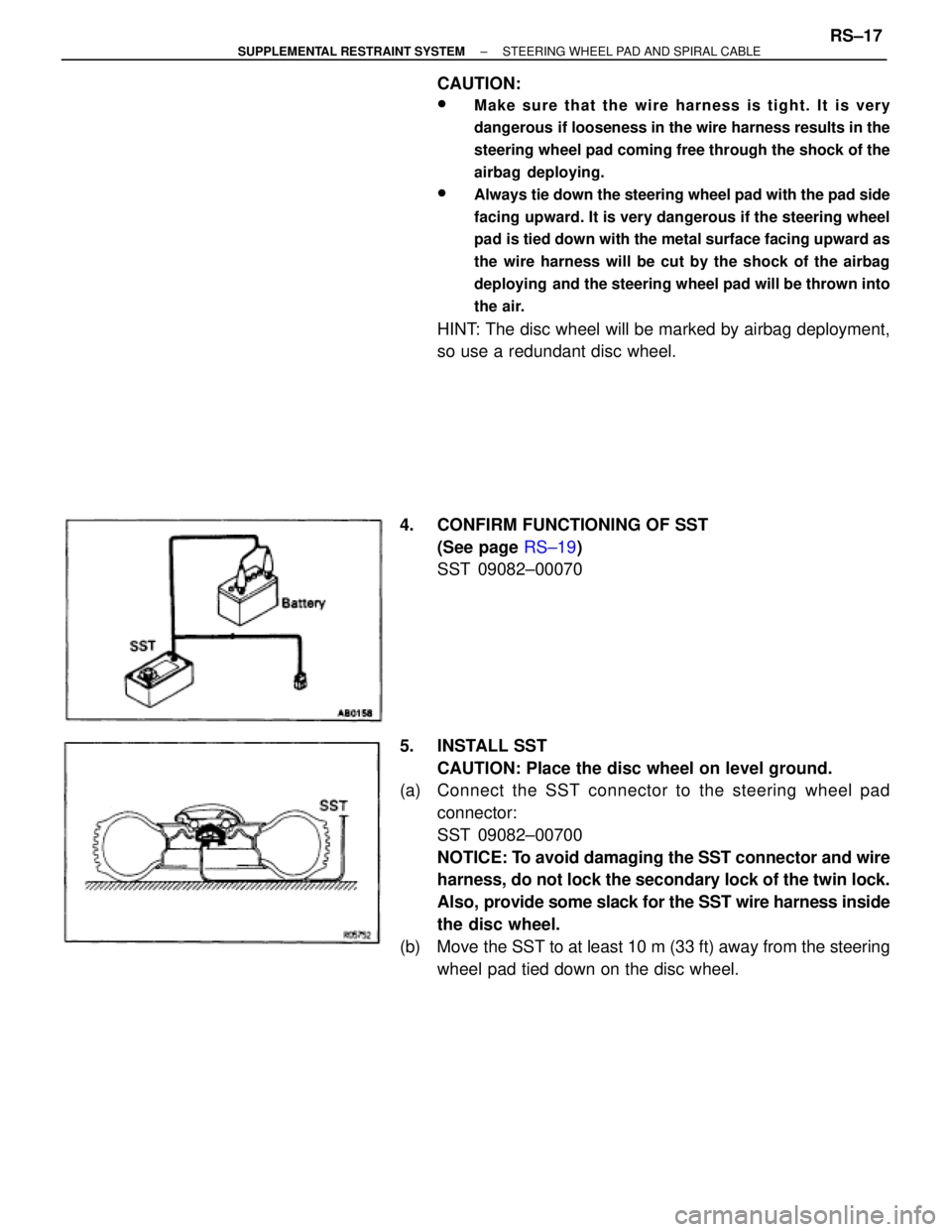
4. CONFIRM FUNCTIONING OF SST
(See page RS±19)
SST 09082±00070
5. INSTALL SST
CAUTION: Place the disc wheel on level ground.
(a) Connect the SST connector to the steering wheel pad
connector:
SST 09082±00700
NOTICE: To avoid damaging the SST connector and wire
harness, do not lock the secondary lock of the twin lock.
Also, provide some slack for the SST wire harness inside
the disc wheel.
(b) Move the SST to at least 10 m (33 ft) away from the steering
wheel pad tied down on the disc wheel.
± SUPPLEMENTAL RESTRAINT SYSTEMSTEERING WHEEL PAD AND SPIRAL CABLERS±17
Page 1701 of 2543
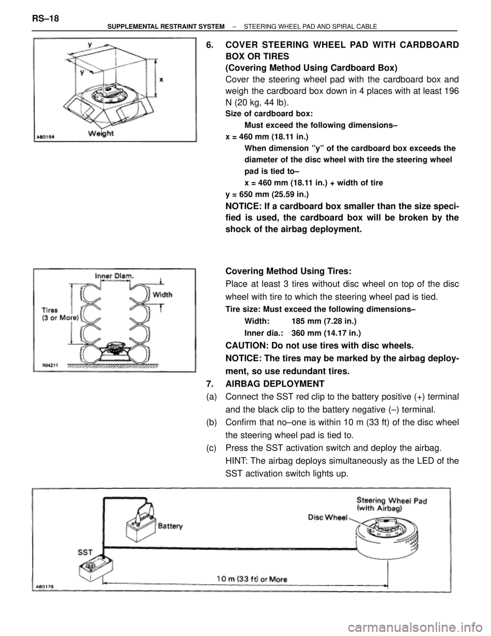
6. COVER STEERING WHEEL PAD WITH CARDBOARD
BOX OR TIRES
(Covering Method Using Cardboard Box)
Cover the steering wheel pad with the cardboard box and
weigh the cardboard box down in 4 places with at least 196
N (20 kg, 44 lb).
Size of cardboard box:
Must exceed the following dimensions±
x = 460 mm (18.11 in.)
When dimension ºyº of the cardboard box exceeds the
diameter of the disc wheel with tire the steering wheel
pad is tied to±
x = 460 mm (18.11 in.) + width of tire
y = 650 mm (25.59 in.)
NOTICE: If a cardboard box smaller than the size speci-
fied is used, the cardboard box will be broken by the
shock of the airbag deployment.
Covering Method Using Tires:
Place at least 3 tires without disc wheel on top of the disc
wheel with tire to which the steering wheel pad is tied.
Tire size: Must exceed the following dimensions±
Width: 185 mm (7.28 in.)
Inner dia.: 360 mm (14.17 in.)
CAUTION: Do not use tires with disc wheels.
NOTICE: The tires may be marked by the airbag deploy-
ment, so use redundant tires.
7. AIRBAG DEPLOYMENT
(a) Connect the SST red clip to the battery positive (+) terminal
and the black clip to the battery negative (±) terminal.
(b) Confirm that no±one is within 10 m (33 ft) of the disc wheel
the steering wheel pad is tied to.
(c) Press the SST activation switch and deploy the airbag.
HINT: The airbag deploys simultaneously as the LED of the
SST activation switch lights up. RS±18
± SUPPLEMENTAL RESTRAINT SYSTEMSTEERING WHEEL PAD AND SPIRAL CABLE
Page 1702 of 2543
8. DISPOSAL OF STEERING WHEEL PAD (WITH AIRBAG)
CAUTION:
wThe steering wheel pad is very hot when the airbag is
deployed, so leave it alone for at least 30 minutes after
deployment.
wUse gloves and safety glasses when handling a steering
wheel pad with a deployed airbag.
wDo not apply water, etc. to a steering wheel pad with a
deployed airbag.
wAlways wash your hands with water after completing the
operation.
(a) Remove the steering wheel pad from the disc wheel.
(b) Place the steering wheel pad in a vinyl bag, tie the end tightly
and dispose of it the same way as other general parts.
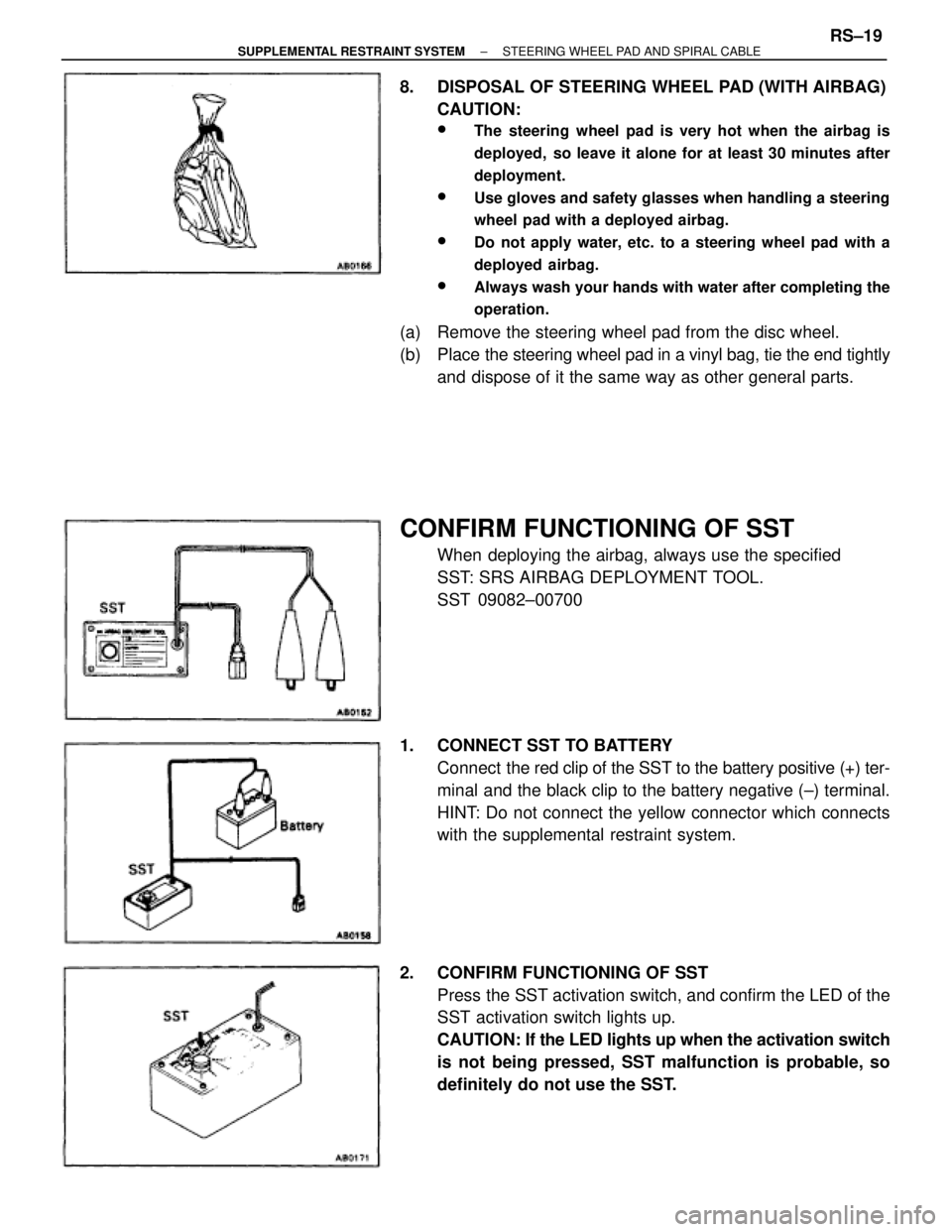
CONFIRM FUNCTIONING OF SST
When deploying the airbag, always use the specified
SST: SRS AIRBAG DEPLOYMENT TOOL.
SST 09082±00700
1. CONNECT SST TO BATTERY
Connect the red clip of the SST to the battery positive (+) ter-
minal and the black clip to the battery negative (±) terminal.
HINT: Do not connect the yellow connector which connects
with the supplemental restraint system.
2. CONFIRM FUNCTIONING OF SST
Press the SST activation switch, and confirm the LED of the
SST activation switch lights up.
CAUTION: If the LED lights up when the activation switch
is not being pressed, SST malfunction is probable, so
definitely do not use the SST.
± SUPPLEMENTAL RESTRAINT SYSTEMSTEERING WHEEL PAD AND SPIRAL CABLERS±19
Page 1729 of 2543
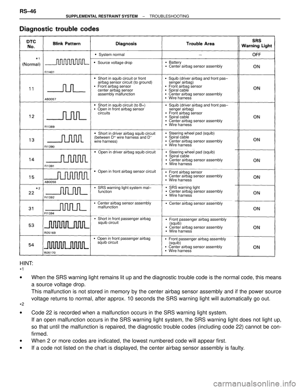
�System normal
�Source voltage drop
�Short in squib circuit or front
airbag sensor circuit (to ground)
�Front airbag sensor
center airbag sensor
assembly malfunction
�Short in squib circuit (to B+)
�Open in front airbag sensor
circuits
�Short in driver airbag squib circuit
(between D+ wire harness and D±
wire harness)
�Open in driver airbag squib circuit
�Open in front airbag sensor circuit
�SRS warning light system mal±
function
�Center airbag sensor assembly
malfunction
�Short in front passenger airbag
squib circuit
�Open in front passenger airbag
squib circuit
�Battery
�Center airbag sensor assembly
�Squib (driver airbag and front pas±
senger airbag)
�Front airbag sensor
�Spiral cable
�Center airbag sensor assembly
�Wire harness
�Squib (driver airbag and front pas±
senger airbag)
�Front airbag sensor
�Spiral cable
�Center airbag sensor assembly
�Wire harness
�Steering wheel pad (squib)
�Spiral cable
�Center airbag sensor assembly
�Wire harness
�Steering wheel pad (squib)
�Spiral cable
�Center airbag sensor assembly
�Wire harness
�Front airbag sensor
�Center airbag sensor assembly
�Wire harness
�SRS warning light
�Center airbag sensor assembly
�Wire harness
�Center airbag sensor assembly
�Front passenger airbag assembly
(squib)
�Center airbag sensor assembly
�Wire harness
�Front passenger airbag assembly
(squib)
�Center airbag sensor assembly
�Wire harness
HINT:
*
1
wWhen the SRS warning light remains lit up and the diagnostic trouble code is the normal code, this means
a source voltage drop.
This malfunction is not stored in memory by the center airbag sensor assembly and if the power source
voltage returns to normal, after approx. 10 seconds the SRS warning light will automatically go out.
*
2
wCode 22 is recorded when a malfunction occurs in the SRS warning light system.
If an open malfunction occurs in the SRS warning light system, the SRS warning light does not light up,
so that until the malfunction is repaired, the diagnostic trouble codes (including code 22) cannot be con-
firmed.
wWhen 2 or more codes are indicated, the lowest numbered code will appear first.
wIf a code not listed on the chart is displayed, the center airbag sensor assembly is faulty. RS±46
± SUPPLEMENTAL RESTRAINT SYSTEMTROUBLESHOOTING
Page 1737 of 2543
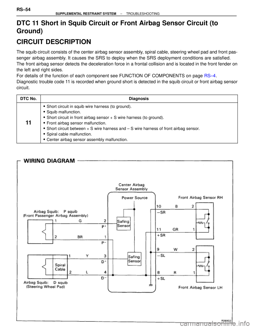
DTC 11 Short in Squib Circuit or Front Airbag Sensor Circuit (to
Ground)
CIRCUIT DESCRIPTION
The squib circuit consists of the center airbag sensor assembly, spiral cable, steering wheel pad and front pas-
senger airbag assembly. It causes the SRS to deploy when the SRS deployment conditions are satisfied.
The front airbag sensor detects the deceleration force in a frontal collision and is located in the front fender on
the left and right sides.
For details of the function of each component see FUNCTION OF COMPONENTS on page RS±4.
Diagnostic trouble code 11 is recorded when ground short is detected in the squib circuit or front airbag sensor
circuit.
����� �
���� �����DTC No.
�������������������������������� �
������������������������������� ��������������������������������Diagnosis
����� �
���� �
���� �
���� �
���� �
���� �����
11
�������������������������������� �
������������������������������� �
������������������������������� �
������������������������������� �
������������������������������� �
������������������������������� ��������������������������������
� Short circuit in squib wire harness (to ground).
� Squib malfunction.
� Short circuit in front airbag sensor + S wire harness (to ground).
� Front airbag sensor malfunction.
� Short circuit between + S wire harness and ± S wire harness of front airbag sensor.
� Spiral cable malfunction.
� Center airbag sensor assembly malfunction.
RS±54± SUPPLEMENTAL RESTRAINT SYSTEMTROUBLESHOOTING
Page 1738 of 2543
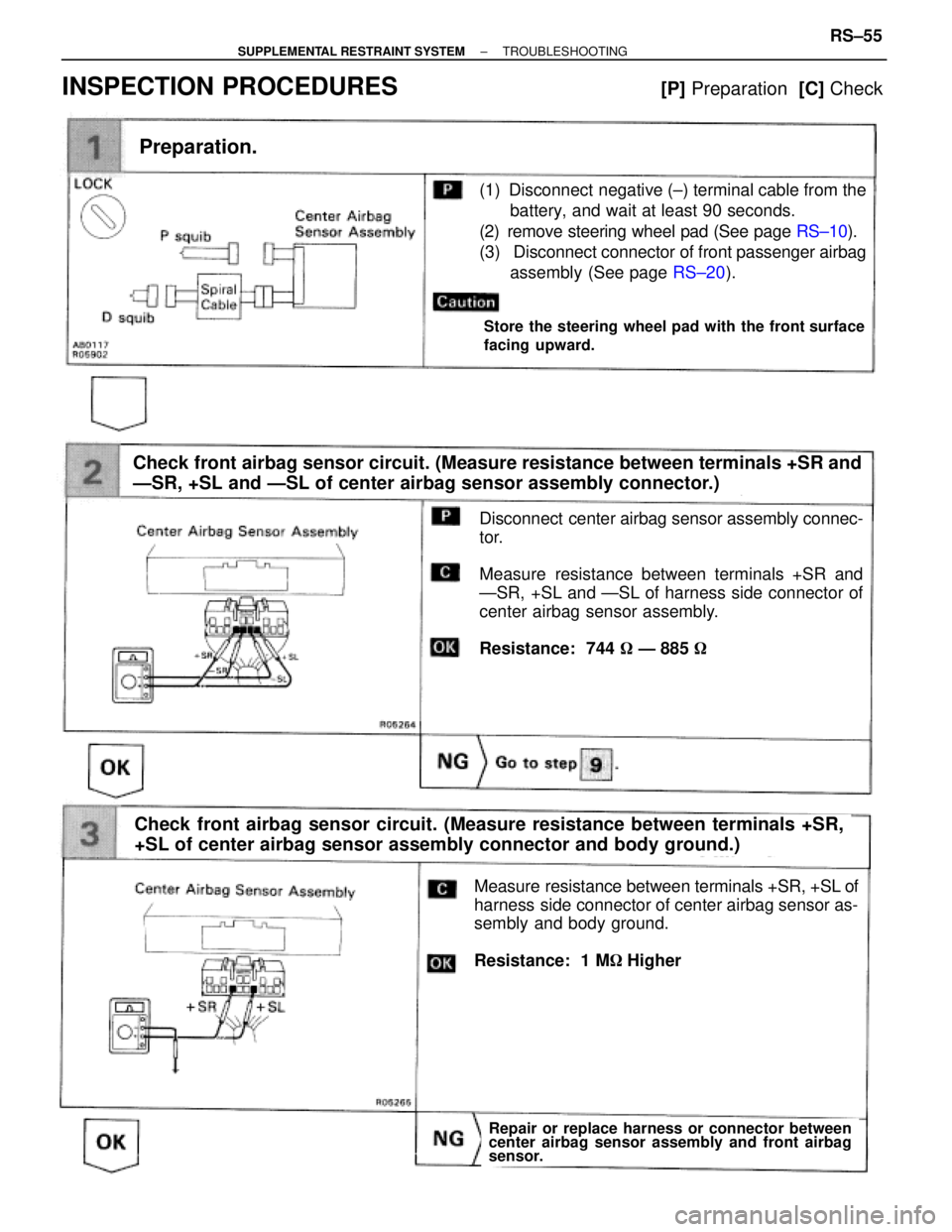
(1) Disconnect negative (±) terminal cable from the
battery, and wait at least 90 seconds.
(2) remove steering wheel pad (See page RS±10).
(3) Disconnect connector of front passenger airbag
assembly (See page RS±20).
Preparation.
Check front airbag sensor circuit. (Measure resistance between terminals +SR and
ÐSR, +SL and ÐSL of center airbag sensor assembly connector.)
Disconnect center airbag sensor assembly connec-
tor.
Measure resistance between terminals +SR and
ÐSR, +SL and ÐSL of harness side connector of
center airbag sensor assembly.
Resistance: 744 � Ð 885 �
Repair or replace harness or connector between
center airbag sensor assembly and front airbag
sensor.
Store the steering wheel pad with the front surface
facing upward.
Check front airbag sensor circuit. (Measure resistance between terminals +SR,
+SL of center airbag sensor assembly connector and body ground.)
Measure resistance between terminals +SR, +SL of
harness side connector of center airbag sensor as-
sembly and body ground.
Resistance: 1 M��Higher
INSPECTION PROCEDURES [P] Preparation [C] Check
± SUPPLEMENTAL RESTRAINT SYSTEMTROUBLESHOOTINGRS±55
Page 1739 of 2543
For the connector (on the spiral cable side) between
the spiral cable and steering wheel pad, measure
the resistance between D
+, D± and body ground.
Resistance: 1 M� or Higher
Check D squib circuit.
Check P squib circuit.
For the connector (on the center airbag sensor as-
sembly side) between the center airbag sensor as-
sembly and front passenger airbag assembly, mea-
sure the resistance between P
+, P± and body
ground.
Resistance: 1 �� or Higher
Repair or replace harness or connector between
center airbag sensor assembly and front airbag
sensor.
RS±56± SUPPLEMENTAL RESTRAINT SYSTEMTROUBLESHOOTING