Page 1776 of 2543
INSPECTION PROCEDURES [P] Preparation [C] Check
Preparation.
(1) Disconnect negative (±) terminal cable from the
battery, and wait at least 90 seconds.
(2) Remove steering wheel pad. (See RS±10)
(3) Disconnect connector of front passenger airbag
assembly. (See page Rs±20)
Repair or replace harness or connector be-
tween center airbag sensor assembly and
front passenger airbag assembly.
Store the steering wheel pad with the front sur-
face facing upward.
Disconnect center airbag sensor assembly connec-
tor.
For the connector (on the center airbag sensor as-
sembly side) between the center airbag sensor as-
sembly and front passenger airbag assembly mea-
sure the resistance between P
+ and P±.
Resistance: Less than 1 �
Check P squib circuit.
± SUPPLEMENTAL RESTRAINT SYSTEMTROUBLESHOOTINGRS±93
Page 1777 of 2543
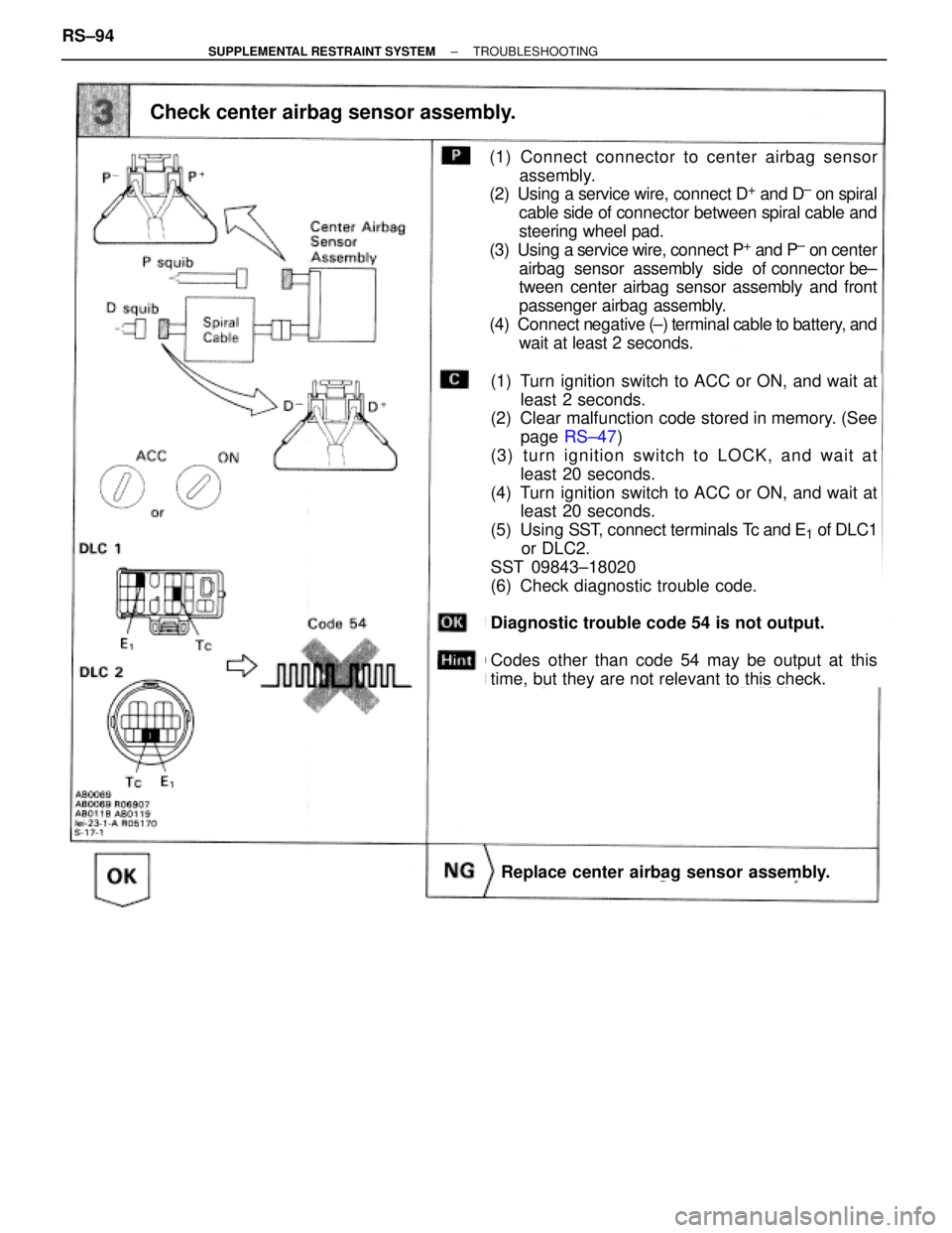
Check center airbag sensor assembly.
(1) Turn ignition switch to ACC or ON, and wait at
least 2 seconds.
(2) Clear malfunction code stored in memory. (See
page RS±47)
(3) turn ignition switch to LOCK, and wait at
least 20 seconds.
(4) Turn ignition switch to ACC or ON, and wait at
least 20 seconds.
(5) Using SST, connect terminals Tc and E
1 of DLC1
or DLC2.
SST 09843±18020
(6) Check diagnostic trouble code.
Diagnostic trouble code 54 is not output.
Codes other than code 54 may be output at this
time, but they are not relevant to this check.
Replace center airbag sensor assembly.
(1) Connect connector to center airbag sensor
assembly.
(2) Using a service wire, connect D
+ and D± on spiral
cable side of connector between spiral cable and
steering wheel pad.
(3) Using a service wire, connect P
+ and P± on center
airbag sensor assembly side of connector be±
tween center airbag sensor assembly and front
passenger airbag assembly.
(4) Connect negative (±) terminal cable to battery, and
wait at least 2 seconds. RS±94
± SUPPLEMENTAL RESTRAINT SYSTEMTROUBLESHOOTING
Page 1785 of 2543
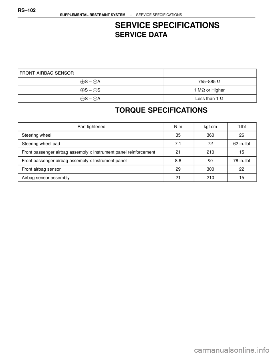
SERVICE SPECIFICATIONS
SERVICE DATA
���������������������� �
��������������������� ����������������������FRONT AIRBAG SENSOR
��������������� �
�������������� ���������������
���������������������� �����������������������S ± �A��������������� ���������������755±885 �
���������������������� �����������������������S ± �S��������������� ���������������1 M� or Higher
���������������������� �����������������������S ± �A��������������� ���������������Less than 1 �
TORQUE SPECIFICATIONS
���������������������� �
���������������������Part tightened������ �
�����NVm������ �
�����kgfVcm����� �
����ftVlbf���������������������� �
��������������������� ����������������������Steering wheel
������ �
����� ������35
������ �
����� ������360
����� �
���� �����26
���������������������� ����������������������Steering wheel pad������ ������7.1������ ������72����� �����62 in.Vlbf
���������������������� ����������������������Front passenger airbag assembly x Instrument panel reinforcement������ ������21������ ������210����� �����15
���������������������� ����������������������Front passenger airbag assembly x Instrument panel������ ������8.8������ ������90����� �����78 in.Vlbf���������������������� �
��������������������� ����������������������Front airbag sensor
������ �
����� ������29
������ �
����� ������300
����� �
���� �����22
���������������������� ����������������������Airbag sensor assembly������ ������21������ ������210����� �����15
RS±102± SUPPLEMENTAL RESTRAINT SYSTEMSERVICE SPECIFICATIONS
Page 1787 of 2543
SA±3SA±3SA±4SA±21
SA±85SA±32
SA±96SA±32
SA±96SA±26,29
SA±89,92SA±13
SA±35SA±20
SA±83SA±3
See Page
Parts
Name
Trouble
Wander / pulls
Bottoming
Sways / pitches
Front wheel shimmy
Abnormal tire wear
Cold tire inflation pressureTiresWheel alignmentSpringsStabilizer barShock absorberBall jointHub bearingsSteering linkageSteering gearSuspension partsOverloadWheel balance
TROUBLESHOOTING
Use the table below to help you find the cause of the problem. The numbers indicate the priority of the likely
cause of the problem. Check each part in order. If necessary, replace these parts. SA±2
± SUSPENSION AND AXLETROUBLESHOOTING
Page 1788 of 2543
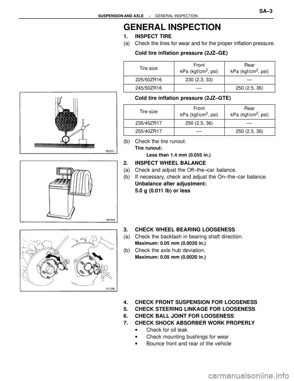
GENERAL INSPECTION
1. INSPECT TIRE
(a) Check the tires for wear and for the proper inflation pressure.
Cold tire inflation pressure (2JZ±GE)
�������� �
������� ��������Tire size�������� �
������� ��������
Front
kPa (kgf/cm2, psi)
�������� �
������� ��������
Rear
kPa (kgf/cm2, psi)
�������� ��������225/50ZR16�������� ��������230 (2.3, 33)�������� ��������±±
�������� ��������245/50ZR16�������� ��������±±�������� ��������250 (2.5, 36)
Cold tire inflation pressure (2JZ±GTE)
�������� �
������� ��������
Tire size�������� �
������� ��������
Front
kPa (kgf/cm2, psi)
�������� �
������� ��������
Rear
kPa (kgf/cm2, psi)
�������� ��������235/45ZR17�������� ��������250 (2.5, 36)�������� ��������±±
�������� ��������255/40ZR17�������� ��������±±�������� ��������250 (2.5, 36)
(b) Check the tire runout.
Tire runout:
Less than 1.4 mm (0.055 in.)
2. INSPECT WHEEL BALANCE
(a) Check and adjust the Off±the±car balance.
(b) If necessary, check and adjust the On±the±car balance.
Unbalance after adjustment:
5.0 g (0.011 lb) or less
3. CHECK WHEEL BEARING LOOSENESS
(a) Check the backlash in bearing shaft direction.
Maximum: 0.05 mm (0.0020 in.)
(b) Check the axle hub deviation.
Maximum: 0.05 mm (0.0020 in.)
4. CHECK FRONT SUSPENSION FOR LOOSENESS
5. CHECK STEERING LINKAGE FOR LOOSENESS
6. CHECK BALL JOINT FOR LOOSENESS
7. CHECK SHOCK ABSORBER WORK PROPERLY
wCheck for oil leak
wCheck mounting bushings for wear
wBounce front and rear of the vehicle
± SUSPENSION AND AXLEGENERAL INSPECTIONSA±3
Page 1789 of 2543
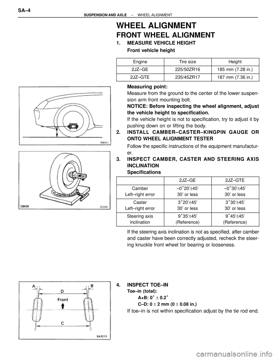
WHEEL ALIGNMENT
FRONT WHEEL ALIGNMENT
1. MEASURE VEHICLE HEIGHT
Front vehicle height
�������� ��������Engine�������� ��������Tire size�������� ��������Height
�������� ��������2JZ±GE�������� ��������225/50ZR16�������� ��������185 mm (7.28 in.)
�������� ��������2JZ±GTE�������� ��������235/45ZR17�������� ��������187 mm (7.36 in.)
Measuring point:
Measure from the ground to the center of the lower suspen-
sion arm front mounting bolt.
NOTICE: Before inspecting the wheel alignment, adjust
the vehicle height to specification.
If the vehicle height is not to specification, try to adjust it by
pushing down on or lifting the body.
2. INSTALL CAMBER±CASTER±KINGPIN GAUGE OR
ONTO WHEEL ALIGNMENT TESTER
Follow the specific instructions of the equipment manufactur-
er.
3. INSPECT CAMBER, CASTER AND STEERING AXIS
INCLINATION
Specifications
�������� ���������������� ��������2JZ±GE�������� ��������2JZ±GTE
�������� �
������� ��������
Camber
Left±right error�������� �
������� ��������
±0°20'+45'
30' or less�������� �
������� ��������
±0°30'+45'
30' or less
�������� �
������� ��������
Caster
Left±right error�������� �
������� ��������
3°20'+45'
30' or less�������� �
������� ��������
3°30'+45'
30' or less
�������� �
������� ��������
Steering axis
inclination�������� �
������� ��������
9°35'+45'
(Reference)�������� �
������� ��������
9°45'+45'
(Reference)
If the steering axis inclination is not as specified, after camber
and caster have been correctly adjusted, recheck the steer-
ing knuckle front wheel for bearing or looseness.
4. INSPECT TOE±IN
Toe±in (total):
A+B: 0° + 0.2°
C±D: 0 + 2 mm (0 + 0.08 in.)
If toe±in is not within specification adjust by the tie rod end. SA±4
± SUSPENSION AND AXLEWHEEL ALIGNMENT
Page 1798 of 2543
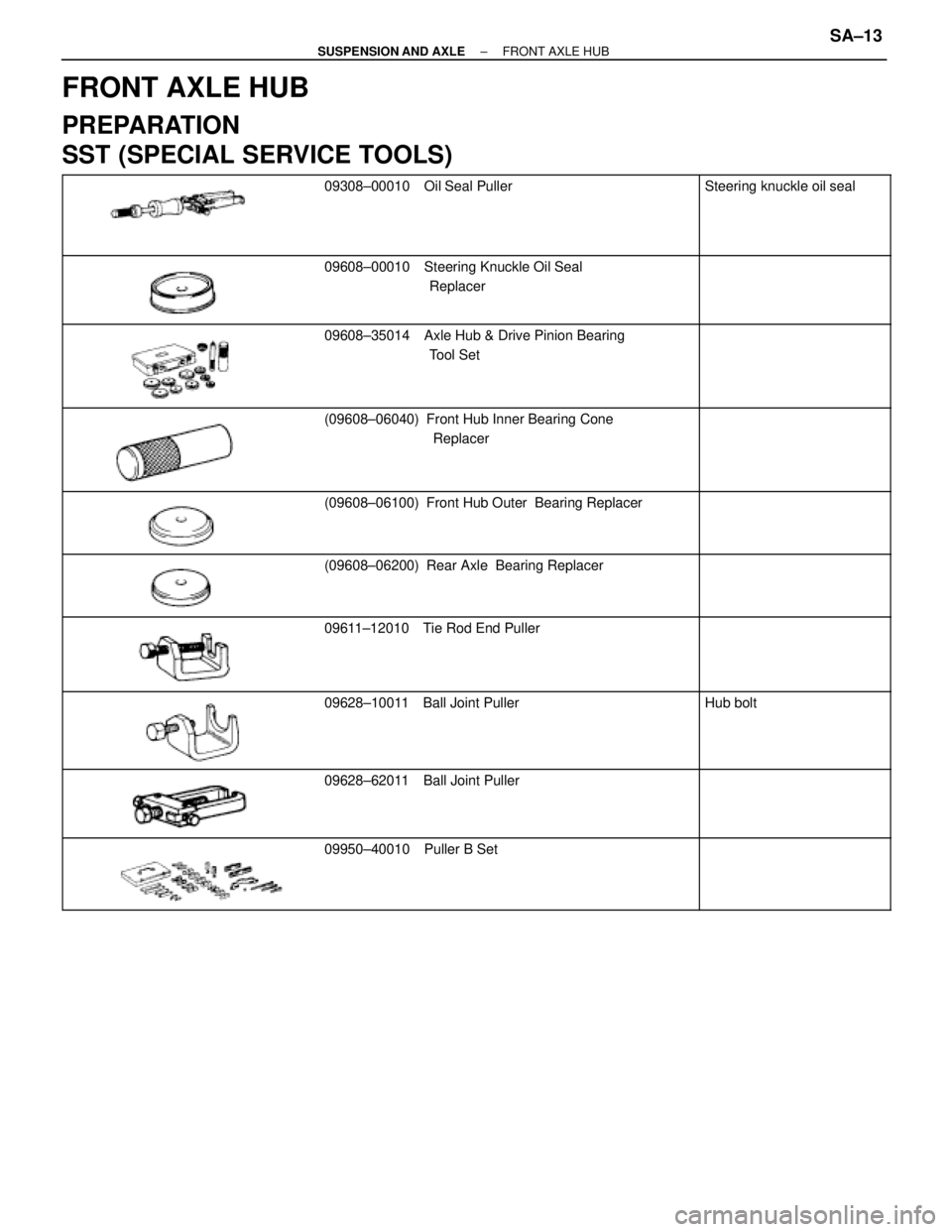
FRONT AXLE HUB
PREPARATION
SST (SPECIAL SERVICE TOOLS)
���������� �
��������� �
��������� ����������
������������������� �
������������������ �
������������������ �������������������
09308±00010 Oil Seal Puller��������� �
�������� �
�������� ���������
Steering knuckle oil seal
���������� �
��������� �
��������� ����������
������������������� �
������������������ �
������������������ �������������������
09608±00010 Steering Knuckle Oil Seal
Replacer��������� �
�������� �
�������� ���������
���������� �
��������� �
��������� �
��������� ����������
������������������� �
������������������ �
������������������ �
������������������ �������������������
09608±35014 Axle Hub & Drive Pinion Bearing
Tool Set��������� �
�������� �
�������� �
�������� ���������
���������� �
��������� �
��������� ����������
������������������� �
������������������ �
������������������ �������������������
(09608±06040) Front Hub Inner Bearing Cone
Replacer��������� �
�������� �
�������� ���������
���������� �
��������� �
��������� ����������
������������������� �
������������������ �
������������������ �������������������
(09608±06100) Front Hub Outer Bearing Replacer��������� �
�������� �
�������� ���������
���������� �
��������� ����������
������������������� �
������������������ �������������������
(09608±06200) Rear Axle Bearing Replacer��������� �
�������� ���������
���������� �
��������� �
��������� ����������
������������������� �
������������������ �
������������������ �������������������
09611±12010 Tie Rod End Puller��������� �
�������� �
�������� ���������
���������� �
��������� �
��������� �
��������� ����������
������������������� �
������������������ �
������������������ �
������������������ �������������������
09628±10011 Ball Joint Puller��������� �
�������� �
�������� �
�������� ���������
Hub bolt
���������� �
��������� �
��������� ����������
������������������� �
������������������ �
������������������ �������������������
09628±62011 Ball Joint Puller��������� �
�������� �
�������� ���������
���������� �
��������� �
��������� ����������
������������������� �
������������������ �
������������������ �������������������
09950±40010 Puller B Set��������� �
�������� �
�������� ���������
± SUSPENSION AND AXLEFRONT AXLE HUBSA±13
Page 1801 of 2543
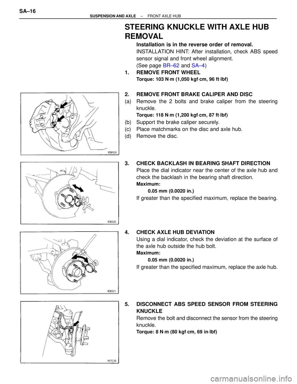
STEERING KNUCKLE WITH AXLE HUB
REMOVAL
Installation is in the reverse order of removal.
INSTALLATION HINT: After installation, check ABS speed
sensor signal and front wheel alignment.
(See page BR±62 and SA±4)
1. REMOVE FRONT WHEEL
Torque: 103 NVm (1,050 kgfVcm, 96 ftVlbf)
2. REMOVE FRONT BRAKE CALIPER AND DISC
(a) Remove the 2 bolts and brake caliper from the steering
knuckle.
Torque: 118 NVm (1,200 kgfVcm, 87 ftVlbf)
(b) Support the brake caliper securely.
(c) Place matchmarks on the disc and axle hub.
(d) Remove the disc.
3. CHECK BACKLASH IN BEARING SHAFT DIRECTION
Place the dial indicator near the center of the axle hub and
check the backlash in the bearing shaft direction.
Maximum:
0.05 mm (0.0020 in.)
If greater than the specified maximum, replace the bearing.
4. CHECK AXLE HUB DEVIATION
Using a dial indicator, check the deviation at the surface of
the axle hub outside the hub bolt.
Maximum:
0.05 mm (0.0020 in.)
If greater than the specified maximum, replace the axle hub.
5. DISCONNECT ABS SPEED SENSOR FROM STEERING
KNUCKLE
Remove the bolt and disconnect the sensor from the steering
knuckle.
Torque: 8 NVm (80 kgfVcm, 69 inVlbf)
SA±16± SUSPENSION AND AXLEFRONT AXLE HUB