Page 1884 of 2543
Cold tire
inflation
pressure
Vehicle height
Front wheel
alignment
Front axle hub
Front
suspension
Rear wheel
alignment
Rear axle hub
Rear
suspension
Rear
drive shaft
Toe±in
Camber
Caster
Steering axis
inclination
Wheel angle
(Max.)
Tie rod end left±right error
Bearing axial direction play
Upper ball joint turning torque
Axle hub flange runout
Bearing axial direction play
Stabilizer bar link ball joint turning torque
Lower ball joint turning torque
Axle hub flange runout
Stabilizer bar link ball joint turning torque
Lower ball joint turning torque
Lower ball joint turning torque
Toe±in
Camber
SERVICE SPECIFICATIONS
SERVICE DATA
± SUSPENSION AND AXLESERVICE SPECIFICATIONSSA±99
Page 1887 of 2543

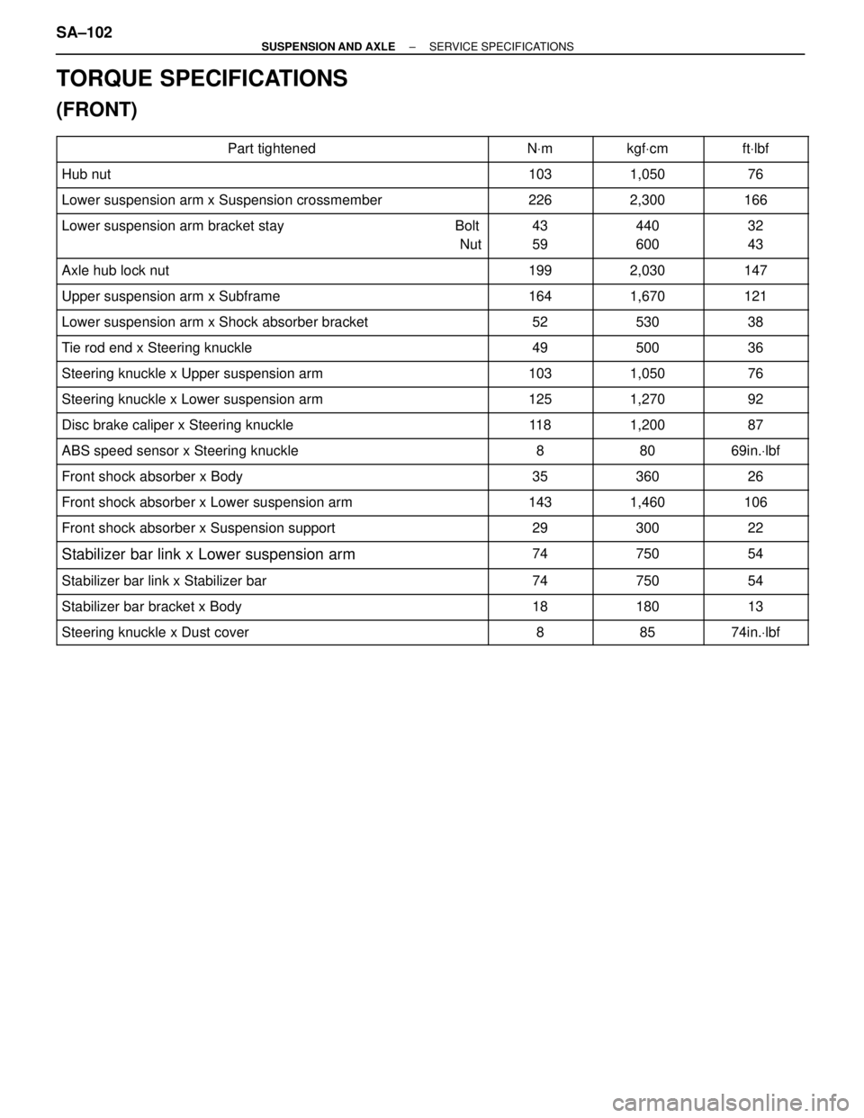
TORQUE SPECIFICATIONS
(FRONT)
��������������������� ���������������������Part tightened������ ������NVm������ ������kgfVcm������ ������ftVlbf
��������������������� ���������������������Hub nut������ ������103������ ������1,050������ ������76
��������������������� ���������������������Lower suspension arm x Suspension crossmember������ ������226������ ������2,300������ ������166��������������������� �
�������������������� ���������������������Lower suspension arm bracket stay Bolt
Nut������ �
����� ������43
59������ �
����� ������440
600������ �
����� ������32
43
��������������������� �
�������������������� ���������������������Axle hub lock nut
������ �
����� ������199
������ �
����� ������2,030
������ �
����� ������147
��������������������� ���������������������Upper suspension arm x Subframe������ ������164������ ������1,670������ ������121
��������������������� ���������������������Lower suspension arm x Shock absorber bracket������ ������52������ ������530������ ������38
��������������������� ���������������������Tie rod end x Steering knuckle������ ������49������ ������500������ ������36
��������������������� ���������������������Steering knuckle x Upper suspension arm������ ������103������ ������1,050������ ������76��������������������� �
�������������������� ���������������������Steering knuckle x Lower suspension arm������ �
����� ������125������ �
����� ������1,270������ �
����� ������92
��������������������� ���������������������Disc brake caliper x Steering knuckle������ ������11 8������ ������1,200������ ������87
��������������������� ���������������������ABS speed sensor x Steering knuckle������ ������8������ ������80������ ������69in.Vlbf
��������������������� ���������������������Front shock absorber x Body������ ������35������ ������360������ ������26
��������������������� ���������������������Front shock absorber x Lower suspension arm������ ������143������ ������1,460������ ������106��������������������� ���������������������Front shock absorber x Suspension support������ ������29������ ������300������ ������22��������������������� �
�������������������� ���������������������Stabilizer bar link x Lower suspension arm
������ �
����� ������74
������ �
����� ������750
������ �
����� ������54
��������������������� ���������������������Stabilizer bar link x Stabilizer bar������ ������74������ ������750������ ������54
��������������������� ���������������������Stabilizer bar bracket x Body������ ������18������ ������180������ ������13
��������������������� ���������������������Steering knuckle x Dust cover������ ������8������ ������85������ ������74in.Vlbf
SA±102± SUSPENSION AND AXLESERVICE SPECIFICATIONS
Page 1955 of 2543

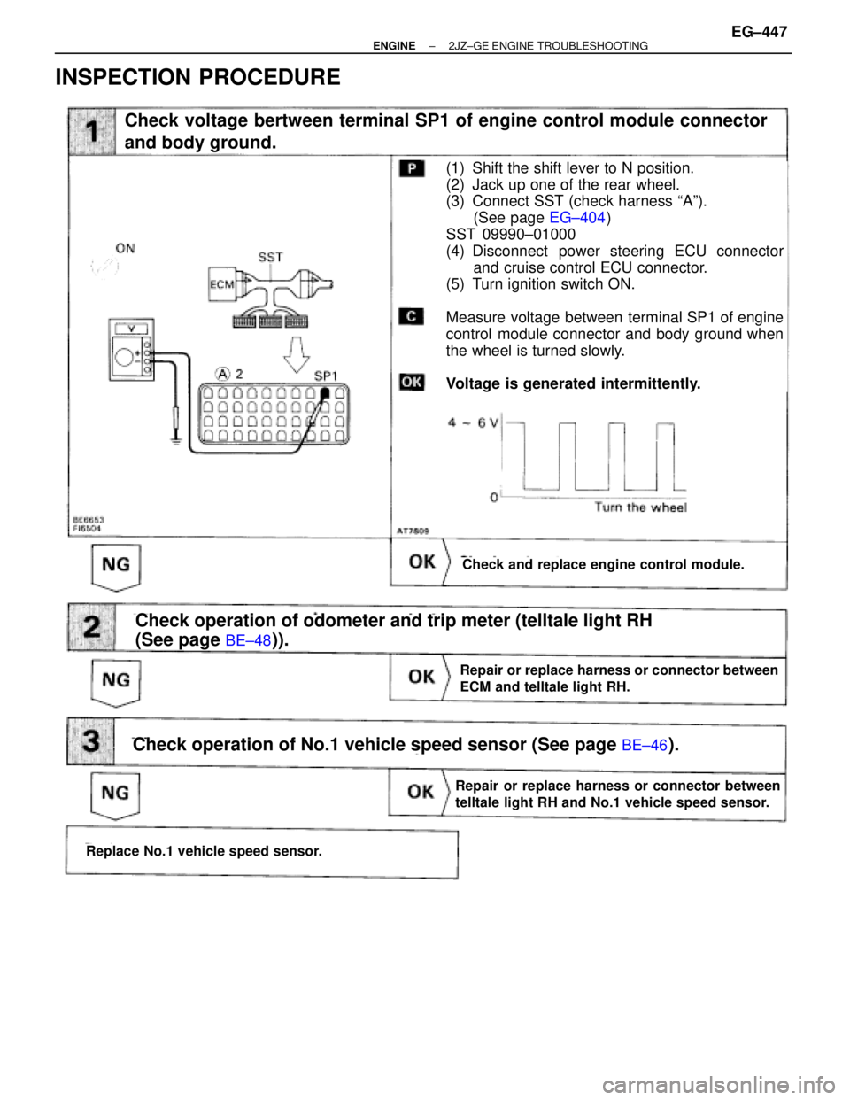
INSPECTION PROCEDURE
(See page
EG±404)
(See page BE±48)).
Check voltage bertween terminal SP1 of engine control module connector
and body ground.
Check and replace engine control module.
(1) Shift the shift lever to N position.
(2) Jack up one of the rear wheel.
(3) Connect SST (check harness ªAº).
(See page EG±404)
SST 09990±01000
(4) Disconnect power steering ECU connector
and cruise control ECU connector.
(5) Turn ignition switch ON.
Measure voltage between terminal SP1 of engine
control module connector and body ground when
the wheel is turned slowly.
Voltage is generated intermittently.
Repair or replace harness or connector between
ECM and telltale light RH.
Check operation of odometer and trip meter (telltale light RH
(See page
BE±48)).
Check operation of No.1 vehicle speed sensor (See page BE±46).
Replace No.1 vehicle speed sensor.
Repair or replace harness or connector between
telltale light RH and No.1 vehicle speed sensor.
± ENGINE2JZ±GE ENGINE TROUBLESHOOTINGEG±447
Page 2065 of 2543
INSPECTION PROCEDURE
(See page EG±510)
(1) Shift the shift lever to N position.
(2) Jack up one of the rear wheels.
(3) Connect SST (check harness ªAº).
(See page
EG±510)
(4) Disconnect power steering ECU connector
and cruise control ECU connector.
(5) Turn ignition switch ON.
Measure voltage between terminal SP1 of engine
control module connector and body ground when
the wheel is turned slowly.
Voltage is generated intermittently.
Check voltage between terminal SP1 of engine control module connector
and body ground.
Check and replace engine control module.
Repair or replace harness or connector between
ECM and telltale light RH.
Repair or replace harness or connector between
telltale light RH and No.1 vehicle speed sensor.
Replace No.1 vehicle speed sensor.
Check operation of odometer and trip meter (telltale light RH
(See page Be±48)).
Check operation of No.1 vehicle speed sensor (See page BE±46).
EG±558± ENGINE2JZ±GTE ENGINE TROUBLESHOOTING