Page 1758 of 2543
Check spiral cable.
Disconnect connector between center airbag sen-
sor assembly and spiral cable.
For connector (on the spiral cable side) between
the spiral cable and steering wheel pad, measure
the resistance between D
+ and D±.
Resistance: Below 1 �
Repair or replace spiral cable.
Check harness between center airbag sensor assembly and spiral cable.
For connector (on the center airbag sensor assem-
bly side) between the center airbag sensor assem-
bly and spiral cable, measure the resistance be-
tween D
+ and D±.
Resistance: Below 1 �
Repair or replace harness or connector between
center airbag sensor assembly and spiral cable.
± SUPPLEMENTAL RESTRAINT SYSTEMTROUBLESHOOTINGRS±75
Page 1759 of 2543

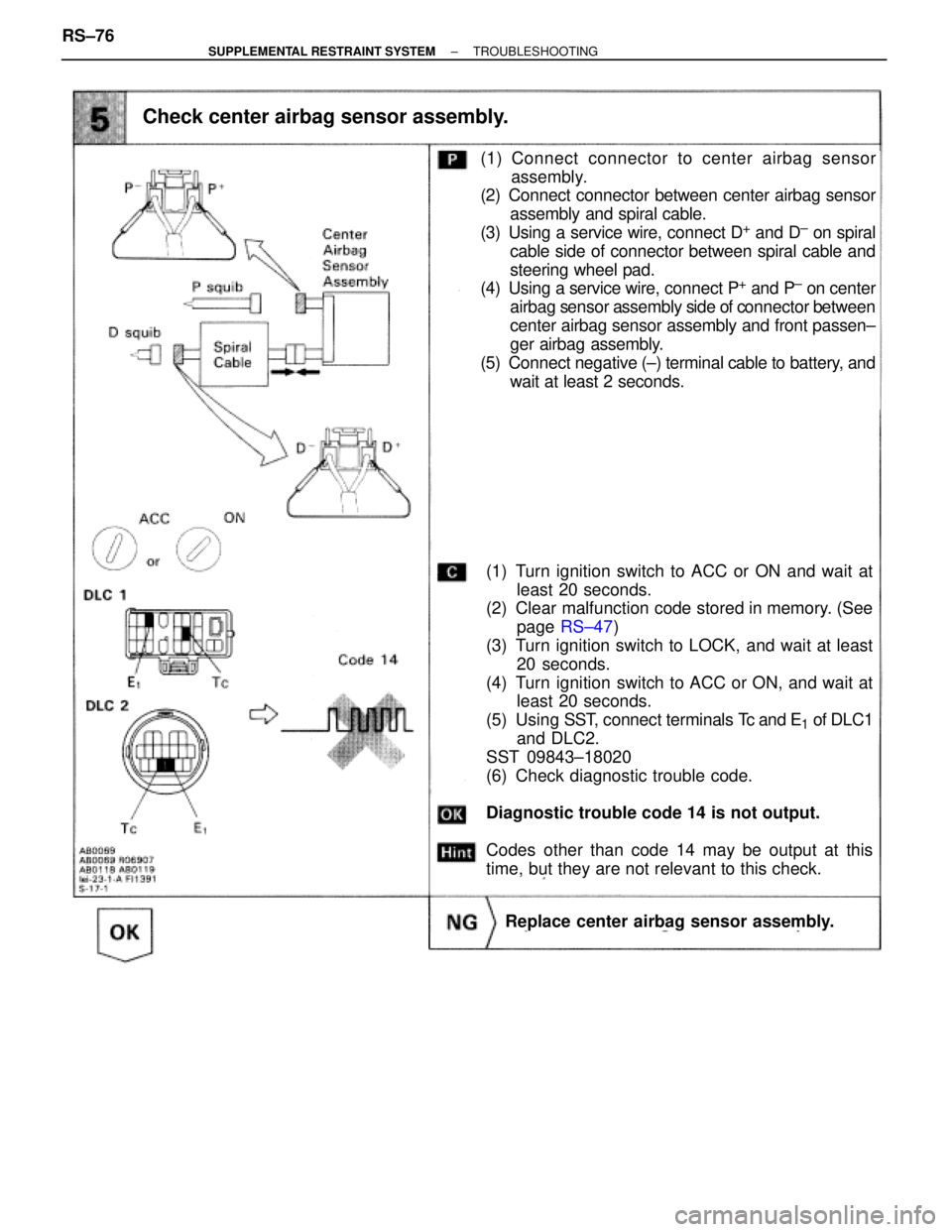
Check center airbag sensor assembly.
(1) Turn ignition switch to ACC or ON and wait at
least 20 seconds.
(2) Clear malfunction code stored in memory. (See
page RS±47)
(3) Turn ignition switch to LOCK, and wait at least
20 seconds.
(4) Turn ignition switch to ACC or ON, and wait at
least 20 seconds.
(5) Using SST, connect terminals Tc and E
1 of DLC1
and DLC2.
SST 09843±18020
(6) Check diagnostic trouble code.
Diagnostic trouble code 14 is not output.
Codes other than code 14 may be output at this
time, but they are not relevant to this check.
Replace center airbag sensor assembly.
(1) Connect connector to center airbag sensor
assembly.
(2) Connect connector between center airbag sensor
assembly and spiral cable.
(3) Using a service wire, connect D
+ and D± on spiral
cable side of connector between spiral cable and
steering wheel pad.
(4) Using a service wire, connect P
+ and P± on center
airbag sensor assembly side of connector between
center airbag sensor assembly and front passen±
ger airbag assembly.
(5) Connect negative (±) terminal cable to battery, and
wait at least 2 seconds. RS±76
± SUPPLEMENTAL RESTRAINT SYSTEMTROUBLESHOOTING
Page 1760 of 2543

From the results of the above inspection, the malfunctioning part can now be considered normal. To make
sure of this, use the simulation method to check.
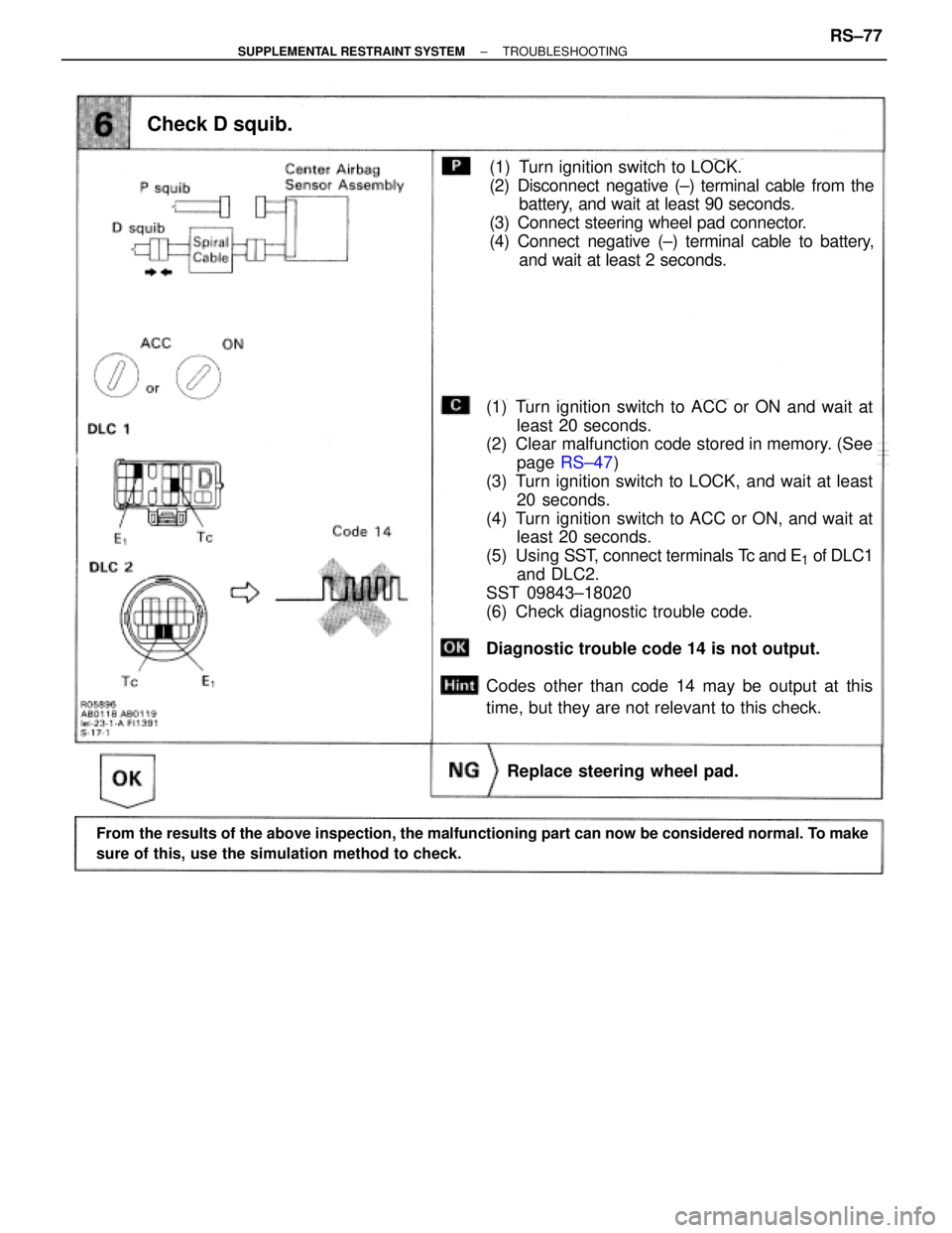
Check D squib.
(1) Turn ignition switch to ACC or ON and wait at
least 20 seconds.
(2) Clear malfunction code stored in memory. (See
page RS±47)
(3) Turn ignition switch to LOCK, and wait at least
20 seconds.
(4) Turn ignition switch to ACC or ON, and wait at
least 20 seconds.
(5) Using SST, connect terminals Tc and E
1 of DLC1
and DLC2.
SST 09843±18020
(6) Check diagnostic trouble code.
Diagnostic trouble code 14 is not output.
Codes other than code 14 may be output at this
time, but they are not relevant to this check.
(1) Turn ignition switch to LOCK.
(2) Disconnect negative (±) terminal cable from the
battery, and wait at least 90 seconds.
(3) Connect steering wheel pad connector.
(4) Connect negative (±) terminal cable to battery,
and wait at least 2 seconds.
Replace steering wheel pad.
± SUPPLEMENTAL RESTRAINT SYSTEMTROUBLESHOOTINGRS±77
Page 1762 of 2543
Preparation.
(1) Disconnect negative (±) terminal cable from the
battery, and wait at least 20 seconds.
(2) Remove steering wheel pad (See page RS±10).
(3) Disconnect connector of front passenger airbag
assembly (See RS20).
Check front airbag sensor circuit (Measure resistance between terminals
+SR and ±SR, +SL and ±SL of center airbag sensor assembly connector.).
Disconnect center airbag sensor assembly connec-
tor.
Measure resistance between terminals +SR and
±SR, +SL and ±SL of harness side connector of
center airbag sensor assembly.
Resistance: 755 � Ð 885 �
Store the steering wheel pad with the front sur-
face facing upward.
INSPECTION PROCEDURES [P] Preparation [C] Check
± SUPPLEMENTAL RESTRAINT SYSTEMTROUBLESHOOTINGRS±79
Page 1763 of 2543

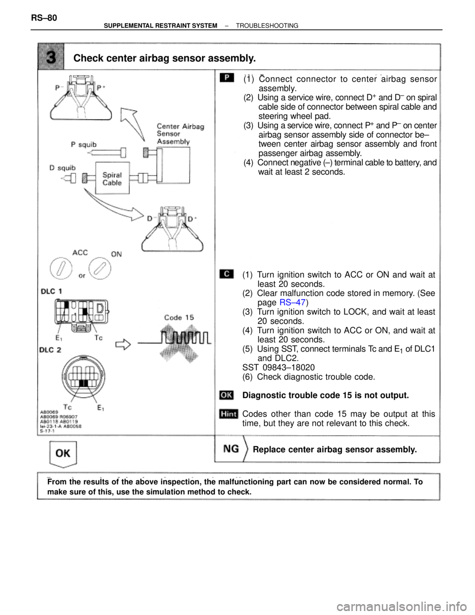
Check center airbag sensor assembly.
(1) Turn ignition switch to ACC or ON and wait at
least 20 seconds.
(2) Clear malfunction code stored in memory. (See
page RS±47)
(3) Turn ignition switch to LOCK, and wait at least
20 seconds.
(4) Turn ignition switch to ACC or ON, and wait at
least 20 seconds.
(5) Using SST, connect terminals Tc and E
1 of DLC1
and DLC2.
SST 09843±18020
(6) Check diagnostic trouble code.
Diagnostic trouble code 15 is not output.
Codes other than code 15 may be output at this
time, but they are not relevant to this check.
Replace center airbag sensor assembly.
(1) Connect connector to center airbag sensor
assembly.
(2) Using a service wire, connect D
+ and D± on spiral
cable side of connector between spiral cable and
steering wheel pad.
(3) Using a service wire, connect P
+ and P± on center
airbag sensor assembly side of connector be±
tween center airbag sensor assembly and front
passenger airbag assembly.
(4) Connect negative (±) terminal cable to battery, and
wait at least 2 seconds.
From the results of the above inspection, the malfunctioning part can now be considered normal. To
make sure of this, use the simulation method to check.
RS±80± SUPPLEMENTAL RESTRAINT SYSTEMTROUBLESHOOTING
Page 1766 of 2543
(See page RS±20).
(See page RS±10).
Check ECU±B Fuse.
Remove ECU±B fuse.
Check continuity of ECU±B fuse.
Continuity
Check connection of center airbag sensor assembly connector.
(1) Disconnect negative (±) terminal cable from the
battery, and wait at least 90 seconds.
(2) Remove steering wheel pad (See page RS±10).
(3) Disconnect connector of front passenger airbag
assembly (See page RS±20).
Preparation.
Repair.
Store the steering wheel pad with the front sur-
face facing upward.
�Fuse may be burnt out even if it appears to be OK
during visual inspection.
�If fuse is OK, install it.
INSPECTION PROCEDURES [P] Preparation [C] Check
HINT: If SRS warning light does not light up, perform the following troubleshooting:
± SUPPLEMENTAL RESTRAINT SYSTEMTROUBLESHOOTINGRS±83
Page 1771 of 2543
Preparation.
Check P squib circuit.
(1) Disconnect negative (±) terminal cable from the
battery, and wait at least 90 seconds.
(2) Remove steering wheel pad (See page RS±10).
(3) Disconnect connector of front passenger airbag
assembly (See page RS±20).
For the connector (on the center airbag sensor as-
sembly side) between the center airbag sensor as-
sembly and front passenger airbag assembly, mea-
sure the resistance between P
+ and P±.
Resistance: 1 k� or higher
Store the steering wheel pad with the front sur-
face facing upward.
INSPECTION PROCEDURES [P] Preparation [C] Check
RS±88± SUPPLEMENTAL RESTRAINT SYSTEMTROUBLESHOOTING
Page 1772 of 2543

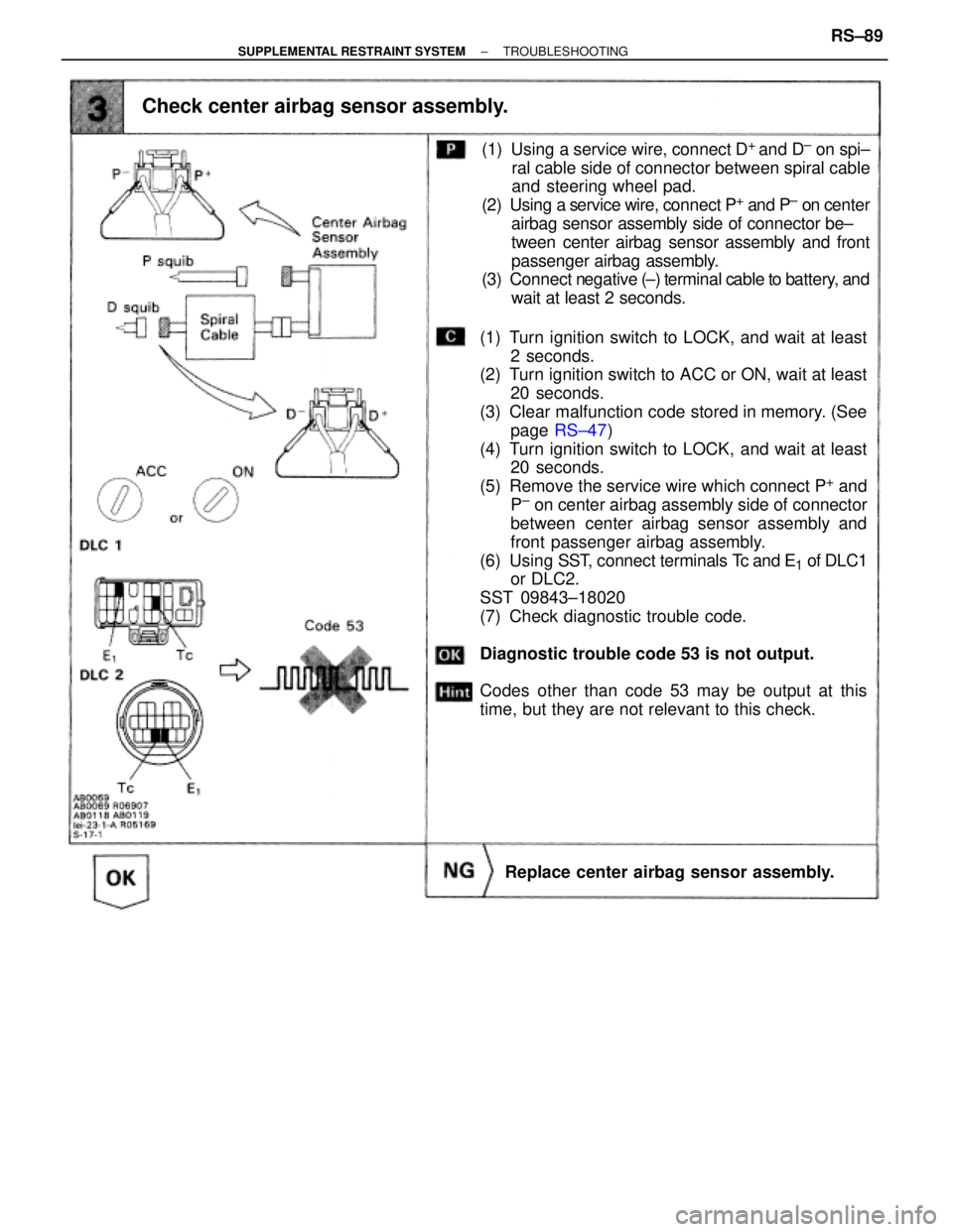
Check center airbag sensor assembly.
(1) Turn ignition switch to LOCK, and wait at least
2 seconds.
(2) Turn ignition switch to ACC or ON, wait at least
20 seconds.
(3) Clear malfunction code stored in memory. (See
page RS±47)
(4) Turn ignition switch to LOCK, and wait at least
20 seconds.
(5) Remove the service wire which connect P
+ and
P± on center airbag assembly side of connector
between center airbag sensor assembly and
front passenger airbag assembly.
(6) Using SST, connect terminals Tc and E
1 of DLC1
or DLC2.
SST 09843±18020
(7) Check diagnostic trouble code.
Diagnostic trouble code 53 is not output.
Codes other than code 53 may be output at this
time, but they are not relevant to this check.
Replace center airbag sensor assembly.
(1) Using a service wire, connect D+
and D± on spi±
ral cable side of connector between spiral cable
and steering wheel pad.
(2) Using a service wire, connect P
+ and P± on center
airbag sensor assembly side of connector be±
tween center airbag sensor assembly and front
passenger airbag assembly.
(3) Connect negative (±) terminal cable to battery, and
wait at least 2 seconds.
± SUPPLEMENTAL RESTRAINT SYSTEMTROUBLESHOOTINGRS±89