Page 1640 of 2248
B4M0236B
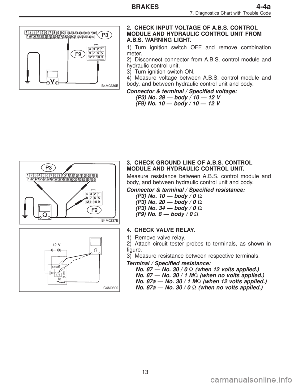
2. CHECK INPUT VOLTAGE OF A.B.S. CONTROL
MODULE AND HYDRAULIC CONTROL UNIT FROM
A.B.S. WARNING LIGHT.
1) Turn ignition switch OFF and remove combination
meter.
2) Disconnect connector from A.B.S. control module and
hydraulic control unit.
3) Turn ignition switch ON.
4) Measure voltage between A.B.S. control module and
body, and between hydraulic control unit and body.
Connector & terminal / Specified voltage:
(P3) No. 29—body / 10—12 V
(F9) No. 10—body / 10—12 V
B4M0237B
3. CHECK GROUND LINE OF A.B.S. CONTROL
MODULE AND HYDRAULIC CONTROL UNIT.
Measure resistance between A.B.S. control module and
body, and between hydraulic control unit and body.
Connector & terminal / Specified resistance:
(P3) No. 10—body / 0Ω
(P3) No. 20—body / 0Ω
(P3) No. 34—body / 0Ω
(F9) No. 8—body / 0Ω
G4M0690
4. CHECK VALVE RELAY.
1) Remove valve relay.
2) Attach circuit tester probes to terminals, as shown in
figure.
3) Measure resistance between respective terminals.
Terminal / Specified resistance:
No. 87—No. 30 / 0Ω(when 12 volts applied.)
No. 87—No.30/1MΩ(when no volts applied.)
No. 87a—No.30/1MΩ(when 12 volts applied.)
No. 87a—No. 30 / 0Ω(when no volts applied.)
13
4-4aBRAKES
7. Diagnostics Chart with Trouble Code
Page 1642 of 2248
B4M0579
B4M0240B
1. CHECK INPUT VOLTAGE TO A.B.S. CONTROL
MODULE FROM A.B.S. WARNING LIGHT.
1) Turn ignition switch OFF.
2) Disconnect connector from A.B.S. control module.
3) Turn ignition switch ON.
4) Measure voltage between A.B.S. control module con-
nector and body.
Connector & terminal / Specified voltage:
(P3) No. 29—Body / 10—12 V
B4M0241B
2. CHECK POWER SUPPLY TO A.B.S. CONTROL
MODULE.
1) Turn ignition switch ON.
2) Measure voltage between A.B.S. control module con-
nector and body.
Connector & terminal / Specified voltage:
(P3) No. 1—Body / 10—12 V
15
4-4aBRAKES
7. Diagnostics Chart with Trouble Code
Page 1645 of 2248
B4M0583
B4M0584A
1. CHECK RESISTANCE OF A.B.S. SENSOR TO
A.B.S. CONTROL MODULE SIDE.
1) Turn ignition switch OFF.
2) Disconnect connector from A.B.S. control module.
3) Measure resistance between A.B.S. control module
connector terminals.
TROUBLE CODE / Connector & terminal:
21 / (P3) No. 23—No. 21
23 / (P3) No. 22—No. 4
25 / (P3) No. 24—No. 26
27 / (P3) No. 8—No. 9
Specified resistance: 0.8—1.2 kΩ
18
4-4aBRAKES
7. Diagnostics Chart with Trouble Code
Page 1646 of 2248
B4M0585A
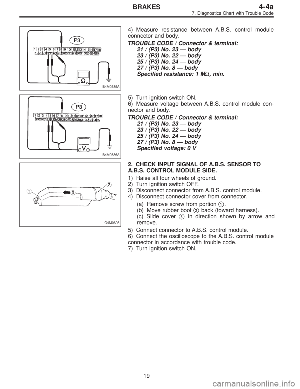
4) Measure resistance between A.B.S. control module
connector and body.
TROUBLE CODE / Connector & terminal:
21 / (P3) No. 23—body
23 / (P3) No. 22—body
25 / (P3) No. 24—body
27 / (P3) No. 8—body
Specified resistance: 1 MΩ, min.
B4M0586A
5) Turn ignition switch ON.
6) Measure voltage between A.B.S. control module con-
nector and body.
TROUBLE CODE / Connector & terminal:
21 / (P3) No. 23—body
23 / (P3) No. 22—body
25 / (P3) No. 24—body
27 / (P3) No. 8—body
Specified voltage: 0 V
G4M0698
2. CHECK INPUT SIGNAL OF A.B.S. SENSOR TO
A.B.S. CONTROL MODULE SIDE.
1) Raise all four wheels of ground.
2) Turn ignition switch OFF.
3) Disconnect connector from A.B.S. control module.
4) Disconnect connector cover from connector.
(a) Remove screw from portion�
1.
(b) Move rubber boot�
2back (toward harness).
(c) Slide cover�
3in direction shown by arrow and
remove.
5) Connect connector to A.B.S. control module.
6) Connect the oscilloscope to the A.B.S. control module
connector in accordance with trouble code.
7) Turn ignition switch ON.
19
4-4aBRAKES
7. Diagnostics Chart with Trouble Code
Page 1648 of 2248
B4M0248B
4. CHECK RESISTANCE OF A.B.S. SENSOR.
1) Turn ignition switch OFF.
2) Disconnect connector from A.B.S. sensor.
3) Measure resistance between A.B.S. sensor connector
terminals.
TROUBLE CODE / Connector & terminal:
21 / (B6) No. 1—No. 2
23 / (B15) No. 1—No. 2
25 / (P8) No. 1—No. 2
27 / (P9) No. 1—No. 2
Specified resistance: 0.8—1.2 kΩ
21
4-4aBRAKES
7. Diagnostics Chart with Trouble Code
Page 1651 of 2248
B4M0711A
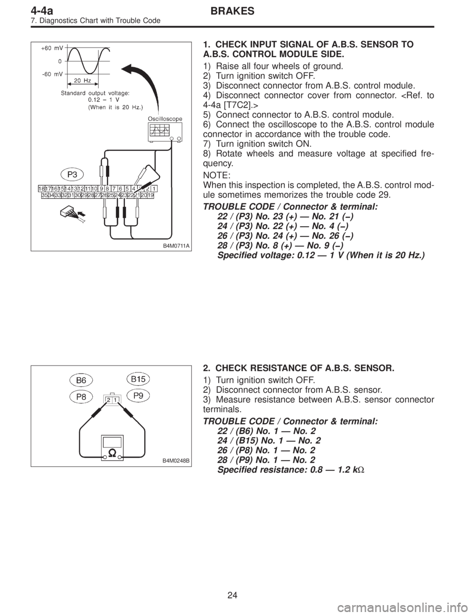
1. CHECK INPUT SIGNAL OF A.B.S. SENSOR TO
A.B.S. CONTROL MODULE SIDE.
1) Raise all four wheels of ground.
2) Turn ignition switch OFF.
3) Disconnect connector from A.B.S. control module.
4) Disconnect connector cover from connector.
4-4a [T7C2].>
5) Connect connector to A.B.S. control module.
6) Connect the oscilloscope to the A.B.S. control module
connector in accordance with the trouble code.
7) Turn ignition switch ON.
8) Rotate wheels and measure voltage at specified fre-
quency.
NOTE:
When this inspection is completed, the A.B.S. control mod-
ule sometimes memorizes the trouble code 29.
TROUBLE CODE / Connector & terminal:
22 / (P3) No. 23 (+)—No. 21 (�)
24 / (P3) No. 22 (+)—No.4(�)
26 / (P3) No. 24 (+)—No. 26 (�)
28 / (P3) No. 8 (+)—No.9(�)
Specified voltage: 0.12—1 V (When it is 20 Hz.)
B4M0248B
2. CHECK RESISTANCE OF A.B.S. SENSOR.
1) Turn ignition switch OFF.
2) Disconnect connector from A.B.S. sensor.
3) Measure resistance between A.B.S. sensor connector
terminals.
TROUBLE CODE / Connector & terminal:
22 / (B6) No. 1—No. 2
24 / (B15) No. 1—No. 2
26 / (P8) No. 1—No. 2
28 / (P9) No. 1—No. 2
Specified resistance: 0.8—1.2 kΩ
24
4-4aBRAKES
7. Diagnostics Chart with Trouble Code
Page 1655 of 2248
B4M0711A
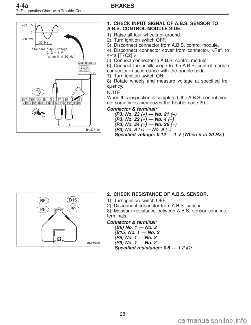
1. CHECK INPUT SIGNAL OF A.B.S. SENSOR TO
A.B.S. CONTROL MODULE SIDE.
1) Raise all four wheels of ground.
2) Turn ignition switch OFF.
3) Disconnect connector from A.B.S. control module.
4) Disconnect connector cover from connector.
4-4a [T7C2].>
5) Connect connector to A.B.S. control module.
6) Connect the oscilloscope to the A.B.S. control module
connector in accordance with the trouble code.
7) Turn ignition switch ON.
8) Rotate wheels and measure voltage at specified fre-
quency.
NOTE:
When this inspection is completed, the A.B.S. control mod-
ule sometimes memorizes the trouble code 29.
Connector & terminal:
(P3) No. 23 (+)—No. 21 (�)
(P3) No. 22 (+)—No.4(�)
(P3) No. 24 (+)—No. 26 (�)
(P3) No. 8 (+)—No.9(�)
Specified voltage: 0.12—1 V (When it is 20 Hz.)
B4M0248B
2. CHECK RESISTANCE OF A.B.S. SENSOR.
1) Turn ignition switch OFF.
2) Disconnect connector from A.B.S. sensor.
3) Measure resistance between A.B.S. sensor connector
terminals.
Connector & terminal:
(B6) No. 1—No. 2
(B15) No. 1—No. 2
(P8) No. 1—No. 2
(P9) No. 1—No. 2
Specified resistance: 0.8—1.2 kΩ
28
4-4aBRAKES
7. Diagnostics Chart with Trouble Code
Page 1658 of 2248
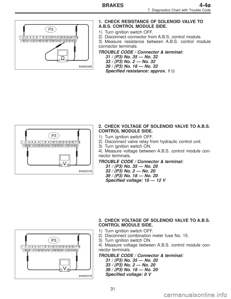
B4M0256B
1. CHECK RESISTANCE OF SOLENOID VALVE TO
A.B.S. CONTROL MODULE SIDE.
1) Turn ignition switch OFF.
2) Disconnect connector from A.B.S. control module.
3) Measure resistance between A.B.S. control module
connector terminals.
TROUBLE CODE / Connector & terminal:
31 / (P3) No. 35—No. 32
33 / (P3) No. 2—No. 32
39 / (P3) No. 18—No. 32
Specified resistance: approx. 1Ω
B4M0257B
2. CHECK VOLTAGE OF SOLENOID VALVE TO A.B.S.
CONTROL MODULE SIDE.
1) Turn ignition switch OFF.
2) Disconnect valve relay from hydraulic control unit.
3) Turn ignition switch ON.
4) Measure voltage between A.B.S. control module con-
nector terminals.
TROUBLE CODE / Connector & terminal:
31 / (P3) No. 35—No. 20
33 / (P3) No. 2—No. 20
39 / (P3) No. 18—No. 20
Specified voltage: 10—12 V
B4M0257B
3. CHECK VOLTAGE OF SOLENOID VALVE TO A.B.S.
CONTROL MODULE SIDE.
1) Turn ignition switch OFF.
2) Disconnect combination meter fuse No. 15.
3) Turn ignition switch ON.
4) Measure voltage between A.B.S. control module con-
nector terminals.
TROUBLE CODE / Connector & terminal:
31 / (P3) No. 35—No. 20
33 / (P3) No. 2—No. 20
39 / (P3) No. 18—No. 20
Specified voltage: 0 V
31
4-4aBRAKES
7. Diagnostics Chart with Trouble Code