Page 1599 of 2248
 Designate mode using function key.
(6) Read data on Subaru select monitor.
Function mode: F09
SPECIFIED DATA:
0.5±0.2 V (Throttle fully closed.)
4.6±0.3 V (Throttle fully open.)
[Must be")
B3M0383
(5) Designate mode using function key.
(6) Read data on Subaru select monitor.
Function mode: F09
SPECIFIED DATA:
0.5±0.2 V (Throttle fully closed.)
4.6±0.3 V (Throttle fully open.)
[Must be changed correspondingly with accelera-
tor pedal operation (from“released”to
“depressed”position).]
B3M0238A
4. CHECK POWER SUPPLY TO THROTTLE POSITION
SENSOR.
1) Turn ignition switch to OFF.
2) Disconnect connector from throttle position sensor.
3) Turn ignition switch to ON.
4) Measure power supply voltage to throttle position sen-
sor.
Connector & terminal / Specified voltage:
(E13) No. 1—Body / 5.12±0.1 V
OBD0145A
�Using Subaru select monitor:
(1) Turn ignition switch to OFF.
(2) Connect the Subaru select monitor to data link con-
nector.
(3) Turn ignition switch to ON and Subaru select moni-
tor switch to ON.
OBD0506
(4) Designate mode using function key.
(5) Read data on Subaru select monitor.
Function mode: F14
SPECIFIED DATA:
5.12±0.1 V
44
3-2AUTOMATIC TRANSMISSION AND DIFFERENTIAL
7. Diagnostic Chart with Trouble Code
Page 1601 of 2248
 Turn ignition switch to OFF.
2) Disconnect connectors from TCM and transmission.
3) Measure resistance of harness connect")
OBD0400A
1. CHECK HARNESS CONNECTOR BETWEEN TCM
AND VEHICLE SPEED SENSOR 1.
1) Turn ignition switch to OFF.
2) Disconnect connectors from TCM and transmission.
3) Measure resistance of harness connector between
TCM and transmission connector.
Connector & terminal / Specified resistance:
(B54) No. 12—(B11) No. 16 / 1Ω, or less
(B54) No. 7—(B11)No.9/1Ω, or less
OBD0401A
4) Measure resistance of harness connector between
TCM and body to make sure that circuit does not short.
Connector & terminal / Specified resistance:
(B54) No. 7—Body/1MΩ, or more
(B54) No. 12—Body/1MΩ, or more
G3M0140
2. CHECK VEHICLE SPEED SENSOR 1.
1) Measure resistance between transmission connector
receptacle’s terminals.
Connector & terminal / Specified resistance:
(T4) No. 16—No. 9 / 450—720Ω
OBD0403A
2) Measure resistance of harness connector between
transmission connector and transmission case to make
sure that circuit does not short.
Connector & terminal / Specified resistance:
(T4) No. 16—Transmission / 1 MΩ, or more
(T4) No. 9—Transmission / 1 MΩ, or more
46
3-2AUTOMATIC TRANSMISSION AND DIFFERENTIAL
7. Diagnostic Chart with Trouble Code
Page 1602 of 2248
 Connect connectors to TCM and transmission.
2) Lift-up or raise the vehicle and place safety stands.
CAUTION:
On AWD models, raise all wheels off floor.
3) P")
OBD0396A
3. CHECK INPUT SIGNAL FOR TCM.
1) Connect connectors to TCM and transmission.
2) Lift-up or raise the vehicle and place safety stands.
CAUTION:
On AWD models, raise all wheels off floor.
3) Push the TCS OFF switch to ON. (With TCS models)
4) Start the engine and set vehicle in 20 km/h (12 MPH)
condition.
5) Measure voltage between TCM connector terminals.
Connector & terminal / Specified voltage:
(B54) No. 12—No. 7 / AC 1 V, or more
NOTE:
The speed difference between front and rear wheels may
light either the ABS or the ABS/TCS warning light, but this
indicates no malfunctions. When AT control diagnosis is
finished, perform the ABS or the ABS/TCS memory clear-
ance procedure of self-diagnosis system.
OBD0145A
B3M0413
OBD0399
�Using Subaru select monitor:
(1) Connect connectors to TCM and transmission.
(2) Turn ignition switch to OFF.
(3) Connect the Subaru select monitor to data link con-
nector.
(4) Lift-up or raise the vehicle and place safety stands.
CAUTION:
On AWD models, raise all wheels off floor.
(5) Turn ignition switch to ON and Subaru select moni-
tor switch to ON.
(6) Push the TCS OFF switch to ON. (With TCS mod-
els)
(7) Start the engine and operate at constant speed.
(8) Read data on Subaru select monitor.
(9) Designate mode using function key.
Function mode: F02 or F03
SPECIFIED DATA:
F02: Compare speedometer with monitor indica-
tions.
F03: Compare speedometer with monitor indica-
tions.
�F02: Vehicle speed is indicated in“m/h”.
�F03: Vehicle speed is indicated in“km/h”.
NOTE:
The speed difference between front and rear wheels may
light either the ABS or the ABS/TCS warning light, but this
indicates no malfunctions. When AT control diagnosis is
finished, perform the ABS or the ABS/TCS memory clear-
ance procedure of self-diagnosis system.
47
3-2AUTOMATIC TRANSMISSION AND DIFFERENTIAL
7. Diagnostic Chart with Trouble Code
Page 1605 of 2248
1. CHECK OPERATION OF SPEEDOMETER.
Make sure that speedometer indicates the vehicle speed
by driving the vehicle.
B3M0250
2. CHECK HARNESS CONNECTOR BETWEEN TCM
AND COMBINATION METER.
1) Turn ignition switch to OFF.
2) Remove combination meter.
B3M0251B
3) Disconnect connectors from TCM.
4) Measure resistance of harness connector between
TCM and combination meter.
Connector & terminal / Specified resistance:
(B56) No. 11—(i10) No. 10 / 1Ω, or less
B3M0414A
5) Measure resistance of harness connector between
combination meter and body to make sure that circuit does
not short.
Connector & terminal / Specified resistance:
(i10) No. 10—Body/1MΩ, or more
50
3-2AUTOMATIC TRANSMISSION AND DIFFERENTIAL
7. Diagnostic Chart with Trouble Code
Page 1608 of 2248
 Install combination meter.
(2) Connect connectors to TCM and vehicle speed
sensor 2.
(3) Lift-up the vehicle or set the vehicle on free roller.
(4) Turn igni")
OBD0145A
�Using Subaru select monitor:
(1) Install combination meter.
(2) Connect connectors to TCM and vehicle speed
sensor 2.
(3) Lift-up the vehicle or set the vehicle on free roller.
(4) Turn ignition switch to OFF.
(5) Connect the Subaru select monitor to data link con-
nector.
(6) Turn ignition switch to ON and Subaru select moni-
tor switch to ON.
CAUTION:
On AWD models, raise all wheels off floor.
(7) Push the TCS OFF switch to ON. (With TCS mod-
els)
G3M0726
B3M0384
(8) Start the engine, and drive the wheels.
(9) Read data on Subaru select monitor.
(10) Designate mode using function key.
Function mode: F04 or F05
SPECIFIED DATA:
Compare speedometer with select monitor indica-
tions.
�F04: Vehicle speed is indicated in mile per hour (MPH).
�F05: Vehicle speed is indicated in kilometer per hour
(km/h).
NOTE:
The speed difference between front and rear wheels may
light either the ABS or the ABS/TCS warning light, but this
indicates no malfunctions. When AT control diagnosis is
finished, perform the ABS or the ABS/TCS memory clear-
ance procedure of self-diagnosis system.
B3M0248B
�Using oscilloscope:
(1) Connect connector to vehicle speed sensor 2.
(2) Lift-up the vehicle or set the vehicle on free rollers.
CAUTION:
On AWD models, raise all wheels off floor.
(3) Set oscilloscope to TCM connector terminals.
Connector & terminals:
Positive probe; (B56) No. 11
Earth lead; Body
53
3-2AUTOMATIC TRANSMISSION AND DIFFERENTIAL
7. Diagnostic Chart with Trouble Code
Page 1613 of 2248
G3M0723
C: MODE F00—MODE DISPLAY—
SPECIFIED DATA:
Data at the left should be indicated.
Probable cause (if outside“specified data”)
1. Communication failure
(No communication method can be confirmed
with power ON.)
�(1)Check loose or poor connectors, or
shortcircuit.
(2) Check type of cartridge.
2. Vehicle types cannot be identified (due to
communication failure).�Check improper cartridge.
Replace with proper one.
G3M0724
D: MODE F01—BATTERY VOLTAGE (VB)—
CONDITION:
�Ignition switch ON
�Engine idling after warm-up
SPECIFIED DATA:
VB: 10—16 V
1. Battery�Check battery voltage and specific gravity of
electrolyte.
2. Charging system�(1)Measure regulating voltage under no loads.
(2) Check generator (as a single unit).
58
3-2AUTOMATIC TRANSMISSION AND DIFFERENTIAL
8. Diagnostic Chart with Select Monitor
Page 1616 of 2248
—
CONDITION:
�Ignition switch ON (with engine OFF)
�Measure voltage while operating throttle valve from a
fully closed position to a fully open p")
B3M0383
I: MODE F09
—THROTTLE POSITION SENSOR (THV)—
CONDITION:
�Ignition switch ON (with engine OFF)
�Measure voltage while operating throttle valve from a
fully closed position to a fully open position.
SPECIFIED DATA:
�Fully closed position: 0.5±0.2 V
�Fully open position: 4.6±0.3 V
�From fully closed to fully open position:
Voltage must smoothly decrease.
�Open harness: 5.0±0.3 V
�Shorted harness: 0.00 V
Probable cause (if outside“specified data”)
1. Throttle position sensor
�Check performance characteristics of throttle
position sensor.
OK
Check TCM and replace if necessary.
G3M0730
J: MODE F10—GEAR POSITION (GEAR)—
CONDITION:
Check while driving vehicle (after warm-up).
SPECIFIED DATA:
Gear position (Refer to shift performance characteristics
chart.)
Probable cause (item outside“specified data”)
1. Shift solenoid 1
�Check performance characteristics of shift solenoid
1.
OK
2. Shift solenoid 2
�Check performance characteristics of shift solenoid
2.
OK
3. Shift solenoid 3
�Check performance characteristics of shift solenoid
3.
OK
Check TCM and replace as necessary.
�
�
�
�
61
3-2AUTOMATIC TRANSMISSION AND DIFFERENTIAL
8. Diagnostic Chart with Select Monitor
Page 1617 of 2248
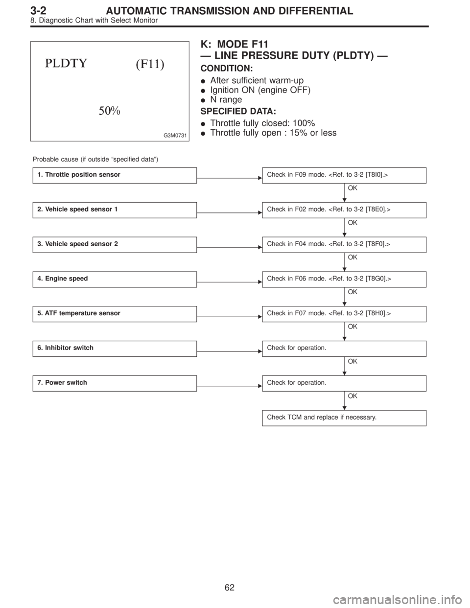
G3M0731
K: MODE F11
—LINE PRESSURE DUTY (PLDTY)—
CONDITION:
�After sufficient warm-up
�Ignition ON (engine OFF)
�N range
SPECIFIED DATA:
�Throttle fully closed: 100%
�Throttle fully open : 15% or less
Probable cause (if outside“specified data”)
1. Throttle position sensor
�Check in F09 mode.
OK
2. Vehicle speed sensor 1
�Check in F02 mode.
OK
3. Vehicle speed sensor 2
�Check in F04 mode.
OK
4. Engine speed
�Check in F06 mode.
OK
5. ATF temperature sensor
�Check in F07 mode.
OK
6. Inhibitor switch
�Check for operation.
OK
7. Power switch
�Check for operation.
OK
Check TCM and replace if necessary.
�
�
�
�
�
�
�
62
3-2AUTOMATIC TRANSMISSION AND DIFFERENTIAL
8. Diagnostic Chart with Select Monitor
 Turn ignition")

1. Communication failure
(No communication method can be con")