Page 1553 of 2248
 Turn ignition switch to ON.
2) Measure voltage between ECM connector and body.
: Connector & terminal
(B84) No.")
1
CHECK TRANSMISSION TYPE.
Refer to flow chart on page 346.
OBD0737A
2
CHECK HARNESS.
1) Turn ignition switch to ON.
2) Measure voltage between ECM connector and body.
: Connector & terminal
(B84) No. 48—Body / 4 V, or more
:�Open circuit of harness between ECM connec-
tor and TCM connector
�Poor contact in ECM connector
�Poor contact in TCM connector
Check the above and repair if necessary.
: Go to next.
: Connector & terminal
(B84) No. 48—Body / 1 V, or less
: Go to step 3.
: Although MIL illuminates, circuit is now normal.
Check all connectors for possible poor contact
between ECM connector and TCM connector.
OBD0519A
3
CHECK HARNESS.
1) Turn ignition switch to OFF.
2) Disconnect connector from ECM.
3) Measure resistance between ECM harness connector
and body.
: Connector & terminal
(B84) No. 48—Body / 10Ω, or less
: Repair short circuit of harness between ECM con-
nector and TCM connector.
: Repair poor contact in ECM connector.
347
2-7ON-BOARD DIAGNOSTICS II SYSTEM
11. Diagnostics Chart with Trouble Code
Page 1554 of 2248
BN:—AT/MT IDENTIFICATION CIRCUIT
MALFUNCTION [MT VEHICLES]—
DESCRIPTION:
The circuit allows the ECM to identify the vehicle as an AT
or MT vehicle.
1.Check harness connector.
CAUTION:
After repair or replacement of faulty parts, conduct
CLEAR MEMORY and INSPECTION MODES.
[T3D0] and [T3E0].>
WIRING DIAGRAM:
OBD0521
OBD0522A
1
CHECK HARNESS CONNECTOR.
1) Turn ignition switch to ON.
2) Measure voltage between ECM and body.
: Connector & terminal
(B84) No. 50—Body / 2 V, or more
: Repair open circuit of harness between ECM con-
nector and body.
: Confirm good connection at ECM connector.
348
2-7ON-BOARD DIAGNOSTICS II SYSTEM
11. Diagnostics Chart with Trouble Code
Page 1562 of 2248
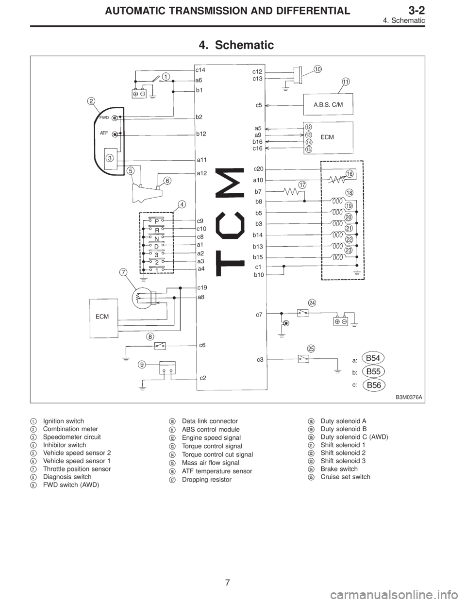
4. Schematic
B3M0376A
�1Ignition switch
�
2Combination meter
�
3Speedometer circuit
�
4Inhibitor switch
�
5Vehicle speed sensor 2
�
6Vehicle speed sensor 1
�
7Throttle position sensor
�
8Diagnosis switch
�
9FWD switch (AWD)�
10Data link connector
�
11ABS control module
�
12Engine speed signal
�
13Torque control signal
�
14Torque control cut signal
�
15Mass air flow signal
�
16ATF temperature sensor
�
17Dropping resistor�
18Duty solenoid A
�
19Duty solenoid B
�
20Duty solenoid C (AWD)
�
21Shift solenoid 1
�
22Shift solenoid 2
�
23Shift solenoid 3
�
24Brake switch
�
25Cruise set switch
7
3-2AUTOMATIC TRANSMISSION AND DIFFERENTIAL
4. Schematic
Page 1563 of 2248

I/O Signal
OBD0093A
Check with ignition switch ON.
ContentConnector
No.Terminal
No.Measuring conditions Voltage (V)
Back-up power supply B56 14 Ignition switch OFF")
5. Transmission Control Module (TCM)
I/O Signal
OBD0093A
Check with ignition switch ON.
ContentConnector
No.Terminal
No.Measuring conditions Voltage (V)
Back-up power supply B56 14 Ignition switch OFF 10—16
Ignition power supplyB54 6
Ignition switch ON (with engine OFF) 10—16
B55 1
Inhibitor switch“P”range switch B56 9Select lever in“P”range Less than 1
Select lever in any other than“P”
range (except“N”range)More than 8
“N”range switch B56 8Select lever in“N”range Less than 1
Select lever in any other than“N”
range (except“P”range)More than 8
“R”range switch B56 10Select lever in“R”range Less than 1
Select lever in any other than“R”
rangeMore than 6
“D”range switch B54 1Select lever in“D”range Less than 1
Select lever in any other than“D”
rangeMore than 6
“3”range switch B54 2Select lever in“3”range Less than 1
Select lever in any other than“3”
rangeMore than 6
“2”range switch B54 3Select lever in“2”range Less than 1
Select lever in any other than“2”
rangeMore than 6
“1”range switch B54 4Select lever in“1”range Less than 1
Select lever in any other than“1”
rangeMore than 6
Diagnosis switch B56 6Diagnosis connector connected Less than 1
Diagnosis connector disconnected More than 6
Brake switch B56 7Brake pedal depressed. More than 10.5
Brake pedal released. Less than 1
ABS signal B56 5ABS switch ON Less than 1
ABS switch OFF More than 6.5
AT diagnostic signal B55 12Ignition switch ON (With engine OFF) Less than 1
Ignition switch ON (With engine ON) More than 10
8
3-2AUTOMATIC TRANSMISSION AND DIFFERENTIAL
5. Transmission Control Module (TCM) I/O Signal
Page 1564 of 2248
Resistance to
body
(ohms)
Throttle position
sensorB54 8Throttle fully closed. 0.5±0.2
—
Throttle fully open. 4.6±0.3
Throttle positio")
ContentConnector
No.Terminal
No.Measuring conditionsVoltage
(V)Resistance to
body
(ohms)
Throttle position
sensorB54 8Throttle fully closed. 0.5±0.2
—
Throttle fully open. 4.6±0.3
Throttle position
sensor power
supplyB56 19Ignition switch ON
(With engine OFF)5.05±0.25—
ATF temperature
sensorB54 10ATF temperature 20°C(68°F) 3.45±0.55 2.1—2.9 k
ATF temperature 80°C (176°F) 1.2±0.2 275—375
Vehicle speed
sensor 1B54 12Vehicle stopped. 0
450—720
Vehicle speed at least 20 km/h (12
MPH)More than 1 (AC range)
Vehicle speed
sensor 2B56 11When vehicle is slowly moved at
least 2 meters (7ft).Less than 1)More than 9—
Engine speed
signalB54 5Ignition switch ON (with engine
OFF).More than 10.5
—
Ignition switch ON (with engine ON). 8—11
Cruise set signal B56 3When cruise control is set (SET
lamp ON).Less than 1
—
When cruise control is not set (SET
lamp OFF).More than 6.5
Torque control
signalB55 16 Ignition switch ON 5±1—
Torque control cut
signalB56 16 Ignition switch ON 6—9—
Mass air flow
signalB54 9 Engine idling after warm-up 0.5—1.2—
Shift solenoid 1 B55 141st or 4th gear More than 9
20—32
2nd or 3rd gear Less than 1
Shift solenoid 2 B55 131st or 2nd gear More than 9
20—32
3rd or 4th gear Less than 1
Shift solenoid 3 B55 15Select lever in“N”range (with
throttle fully closed).Less than 1
20—32
Select lever in“D”range (with
throttle fully closed).More than 9
Duty solenoid A B55 8Throttle fully closed (with engine
OFF) after warm-up.1.5—4.0
2.0—4.5
Throttle fully open (with engine
OFF) after warm-up.Less than 1
Dropping resistor B55 7Throttle fully closed (with engine
OFF) after warm-up.More than 8.5
12—18
Throttle fully open (with engine
OFF) after warm-up.Less than 1
Duty solenoid B B55 5When lock up occurs. More than 8.5
9—17
When lock up is released. Less than 0.5
Duty solenoid C
(AWD model only)B55 3Fuse on FWD switch More than 8.5
9—17 Fuse removed from FWD switch
(with throttle fully open and with
select lever in 1st gear).Less than 0.5
Sensor ground
line 1B54 7—0 Less than 1
Sensor ground
line 2B56 20—0 Less than 1
System ground
lineB56 1—0 Less than 1
Power system
ground lineB55 10—0 Less than 1
FWD switch
(AWD model only)B56 2Fuse removed. 6—9.1
—
Fuse installed. Less than 1
9
3-2AUTOMATIC TRANSMISSION AND DIFFERENTIAL
5. Transmission Control Module (TCM) I/O Signal
Page 1567 of 2248
C: ON-BOARD DIAGNOSTICS
* : Blinks every 0.125 (1/8) seconds (until ignition switch is turned OFF).
** : Blinks every 0.25 (1/4) seconds (until ignition switch is turned OFF).
*** : Plug in diagnosis terminal to diagnosis connector No. 5 located below instrument lower cover.
12
3-2AUTOMATIC TRANSMISSION AND DIFFERENTIAL
6. Diagnostic Chart for On-board Diagnostic System
Page 1569 of 2248
 indicates a“ten”, and the
short se")
2. HOW TO READ TROUBLE CODE OF INDICATOR
LIGHT
The AT OIL TEMP indicator light flashes the code corre-
sponding to the faulty part.
The long segment (1.2 sec on) indicates a“ten”, and the
short segment (0.2 sec on) signifies a“one”.
B3M0193A
E: CLEAR MEMORY
Current trouble codes shown on the display are cleared by
turning the ignition switch OFF after conducting on-board
diagnostic operation. Previous trouble codes, however,
cannot be cleared since they are stored in the TCM
memory which is operating on the back-up power supply.
These trouble codes can be cleared by removing the speci-
fied fuse (located under the right lower portion of the instru-
ment panel).
CLEAR MEMORY:
Removal of No. 14 fuse (for at least one minute)
�The No. 14 fuse is located in the line to the memory
back-up power supply of the TCM and ABS/TCS control
module. Removal of this fuse clears the previous trouble
codes stored in the TCM and ABS/TCS control module
memory.
�Be sure to remove the No. 14 fuse for at least the speci-
fied length of time. Otherwise, trouble codes may not be
cleared.
14
3-2AUTOMATIC TRANSMISSION AND DIFFERENTIAL
6. Diagnostic Chart for On-board Diagnostic System
Page 1571 of 2248
 Turn ignition switch to OFF.
2) Disconnect connectors from TCM, transmission and
resistor.
3) Measur")
OBD0428A
1. CHECK HARNESSES AND CONNECTORS
BETWEEN TCM AND DUTY SOLENOID A AND
BETWEEN RESISTOR.
1) Turn ignition switch to OFF.
2) Disconnect connectors from TCM, transmission and
resistor.
3) Measure resistance of harness connector between
TCM and transmission.
Connector & terminal / Specified resistance:
(B55) No. 8 — (B11) No.7/1Ω, or less
OBD0429A
4) Measure resistance of harness connector between
TCM and body to make sure that circuit does not short.
Connector & terminal / Specified resistance:
(B55) No. 8 — Body/1MΩ, or more
B3M0196B
5) Measure resistance of harness connector between
TCM and resistor connector.
Connector & terminal / Specified resistance:
(B55) No. 7 — (B4) No.1/1Ω, or less
B3M0197B
6) Measure resistance of harness connector between
TCM and body to make sure that circuit does not short.
Connector & terminal / Specified resistance:
(B55) No. 7 — Body/1MΩ, or more
G3M0109
2. CHECK DUTY SOLENOID A’s GROUND LINE.
Measure resistance between transmission connector
receptacle (on transmission) and transmission case.
Connector & terminal / Specified resistance:
(T4) No. 4 — Transmission / 1Ω, or less
16
3-2AUTOMATIC TRANSMISSION AND DIFFERENTIAL
7. Diagnostic Chart with Trouble Code
![SUBARU LEGACY 1995 Service Repair Manual BN:—AT/MT IDENTIFICATION CIRCUIT
MALFUNCTION [MT VEHICLES]—
DESCRIPTION:
The circuit allows the ECM to identify the vehicle as an AT
or MT vehicle.
1.Check harness connector.
CAUTION:
After repair](/manual-img/17/57432/w960_57432-1553.png "SUBARU LEGACY 1995 Service Repair Manual BN:—AT/MT IDENTIFICATION CIRCUIT
MALFUNCTION [MT VEHICLES]—
DESCRIPTION:
The circuit allows the ECM to identify the vehicle as an AT
or MT vehicle.
1.Check harness connector.
CAUTION:
After repair")
 seconds (until ignition switch is turned OFF).
** : Blinks every 0.25 (1/4) seconds (until ignition switch is turned OFF).
*** : Plug in diagnosis")