Page 1619 of 2248
G3M0733
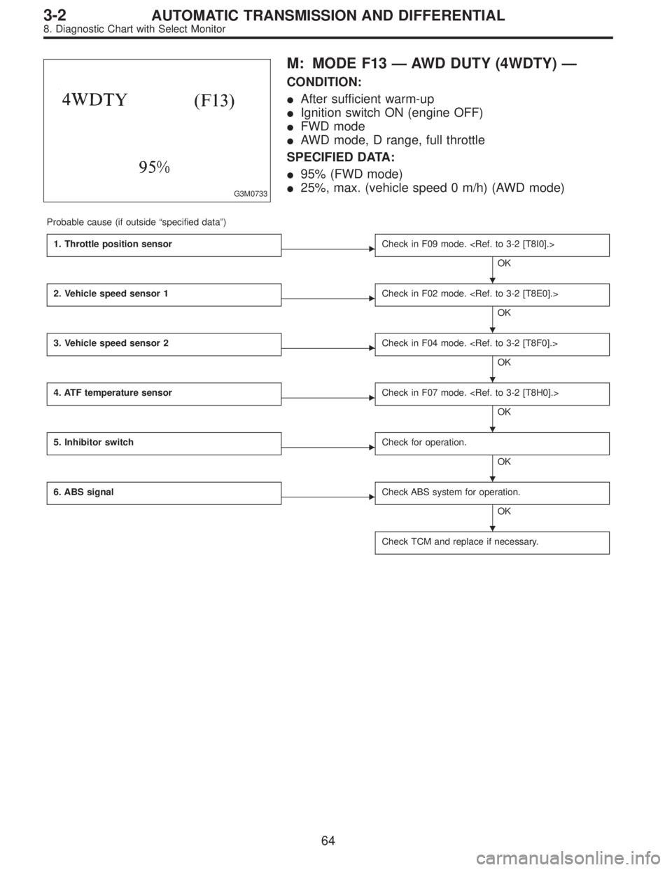
M: MODE F13—AWD DUTY (4WDTY)—
CONDITION:
�After sufficient warm-up
�Ignition switch ON (engine OFF)
�FWD mode
�AWD mode, D range, full throttle
SPECIFIED DATA:
�95% (FWD mode)
�25%, max. (vehicle speed 0 m/h) (AWD mode)
Probable cause (if outside“specified data”)
1. Throttle position sensor
�Check in F09 mode.
OK
2. Vehicle speed sensor 1
�Check in F02 mode.
OK
3. Vehicle speed sensor 2
�Check in F04 mode.
OK
4. ATF temperature sensor
�Check in F07 mode.
OK
5. Inhibitor switch
�Check for operation.
OK
6. ABS signal
�Check ABS system for operation.
OK
Check TCM and replace if necessary.
�
�
�
�
�
�
64
3-2AUTOMATIC TRANSMISSION AND DIFFERENTIAL
8. Diagnostic Chart with Select Monitor
Page 1620 of 2248
B3M0259
N: MODE F14
—THROTTLE POSITION SENSOR POWER
SUPPLY (THVCC)—
CONDITION:
Ignition switch ON (engine OFF)
SPECIFIED DATA:
5.12±0.1 V
Probable cause (Item outside“specified data”)
1. Throttle position sensor power supply
�Check throttle sensor line.
OK
Check TCM and replace if necessary.
B3M0370
O: MODE F15
—MASS AIR FLOW SIGNAL (AFM)—
CONDITION:
�Ignition switch ON (engine ON)
�N range
�Idling
SPECIFIED DATA:
Engine warm-up: 0.5—1.2 V
Probable cause (if outside“specified data”)
1. Mass air flow signal
�Check performance characteristics of mass air flow
signal.
OK
Check TCM and replace if necessary.
�
�
65
3-2AUTOMATIC TRANSMISSION AND DIFFERENTIAL
8. Diagnostic Chart with Select Monitor
Page 1623 of 2248
 Turn ignition switch OFF.
2) Disconnect connector from TCM.
3) Measure resistance of harness connector between
TCM and diagnosi")
B3M0373A
1. CHECK HARNESS CONNECTOR BETWEEN TCM
AND DIAGNOSIS SWITCH.
1) Turn ignition switch OFF.
2) Disconnect connector from TCM.
3) Measure resistance of harness connector between
TCM and diagnosis switch.
Connector & terminal / Specified resistance:
(B56) No. 6—(B82) No.5/1Ω, or less.
B3M0273B
4) Measure resistance of harness connector between
TCM and body to make sure that circuit does not short.
Connector & terminal / Specified resistance:
(B56) No.6—Body / 1 MΩ, or more
B3M0271B
2. CHECK INPUT SIGNAL FOR TCM.
1) Connect connector to TCM.
2) Turn ignition switch ON (with engine OFF).
3) Measure signal voltage for TCM while connecting and
disconnecting the diagnosis terminal to diagnosis connec-
tor.
Connector & terminal / Specified voltage:
(B56) No. 6—Body / Less than 1 V (Connected)
More than 6 V (Discon-
nected)
B4M0387A
3. CHECK DIAGNOSIS SWITCH GROUND LINE.
Measure resistance of harness terminal between diagnosis
terminal and body.
Connector & terminal / Specified resistance:
(B81)—Body / 1Ω, or less
68
3-2AUTOMATIC TRANSMISSION AND DIFFERENTIAL
8. Diagnostic Chart with Select Monitor
Page 1631 of 2248
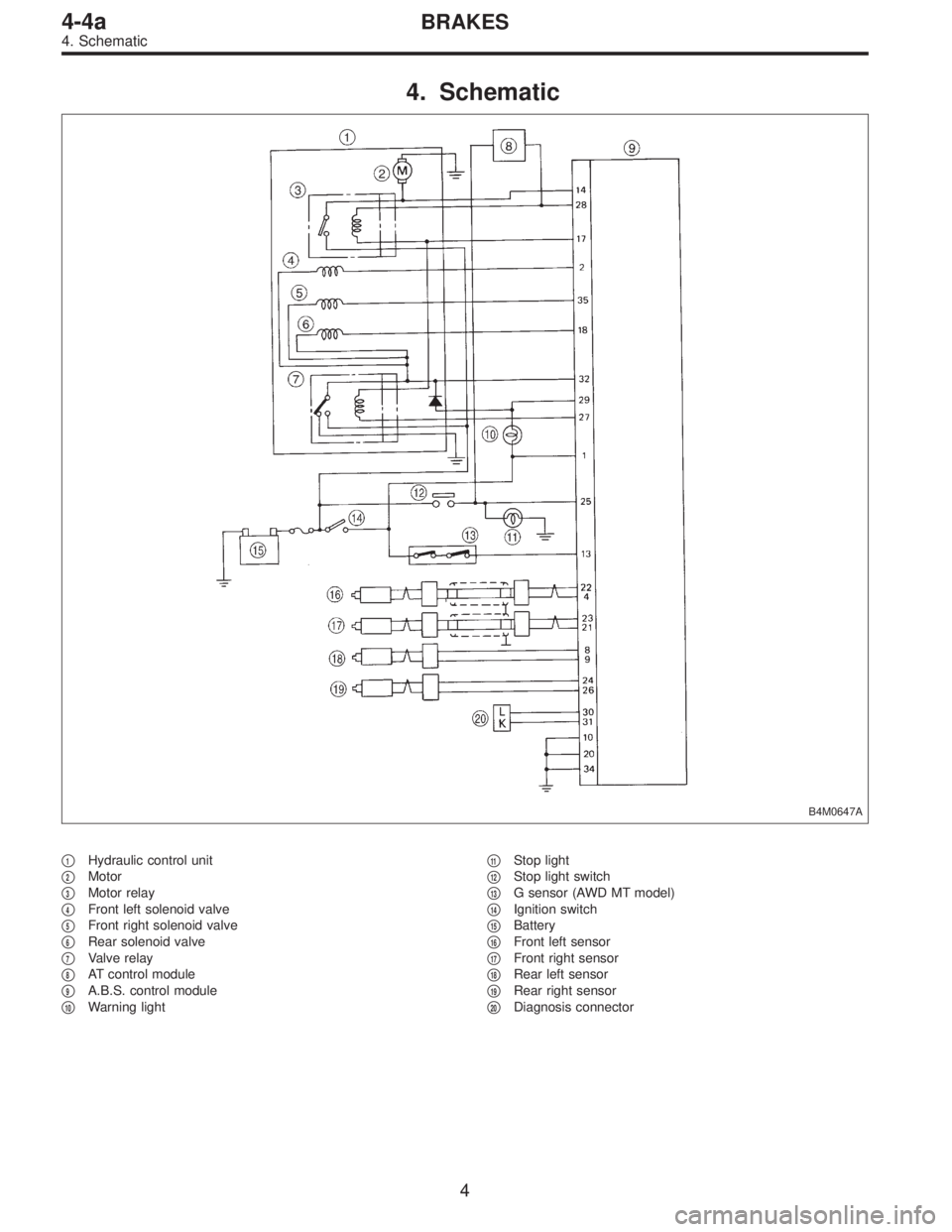
4. Schematic
B4M0647A
�1Hydraulic control unit
�
2Motor
�
3Motor relay
�
4Front left solenoid valve
�
5Front right solenoid valve
�
6Rear solenoid valve
�
7Valve relay
�
8AT control module
�
9A.B.S. control module
�
10Warning light�
11Stop light
�
12Stop light switch
�
13G sensor (AWD MT model)
�
14Ignition switch
�
15Battery
�
16Front left sensor
�
17Front right sensor
�
18Rear left sensor
�
19Rear right sensor
�
20Diagnosis connector
4
4-4aBRAKES
4. Schematic
Page 1632 of 2248

5. Control Module I/O Signal
1. I/O SIGNAL VOLTAGE
G4M0685
ContentsTerminal
No.Ignition
switch ON,
engine
OFFInput/output signals
Measured value Measuring conditions
A.B.S.
sensorFront left wheel 22
0 V 0.12—1V�No. 22—No. 4
(When it is 10 Hz.)
GND 4
Front right wheel 23
0 V 0.12—1V�No. 23—No. 21
(When it is 10 Hz.)
GND 21
Rear left wheel 8
0 V 0.12—1V�No. 8—No. 9
(When it is 10 Hz.)
GND 9
Rear right wheel 24
0 V 0.12—1V�No. 24—No. 26
(When it is 10 Hz.)
GND 26
G sensor (AWD MT model) 13 10—12 V 0 V When slanting about 14°—21.3°(θ)
Diagnosis connector30
—— —
31
Stop light switch 25 0 V 10—12 V When brake pedal is depressed.
Motor monitoring 14 0 V 10—12 V When motor operates.
Valve power supply monitoring 32 10—12 V 10—12 V Ignition switch ON*1
Hydraulic
control
unitSolenoidFront left
wheel210—12 V 0 V
When solenoid is energized to
produce output. Front right
wheel35 10—12 V 0 V
Rear wheel 18 10—12 V 0 V
Valve relay coil 27 0 V 0 V Ignition switch ON*2
Motor relay coil 28 10—12 V 0 VWhen motor operates to produce
output.
Warning light 29 10—12 V 10—12 V Ignition switch ON*3
Power
supplyIgnition 1 10—12 V 10—12 V Ignition switch ON
Relay coil (valve,
motor, etc.)17 10—12 V 10—12 V Ignition switch ON
Grounding line10 0V 0V—
20 0V 0V—
34 0V 0V—
*1: When ignition switch is OFF or the A.B.S. system is inactive: 0 V
*2: When ignition switch is OFF or the A.B.S. system is inactive: 10—12 V
*3: When ignition switch is OFF or the A.B.S. system is inactive, or during 1.5 seconds from ignition switch ON: 0 V
5
4-4aBRAKES
5. Control Module I/O Signal
Page 1635 of 2248

or more for at least 20 seconds. If a problem is found, the
A.B.S")
B: INSPECTION MODE
The on-board diagnosis system is designed to detect prob-
lems after the vehicle has been driven at 10 km/h (6 MPH)
or more for at least 20 seconds. If a problem is found, the
A.B.S. warning light will illuminate to inform the driver of the
occurrence of a problem. When the warning light is on, the
A.B.S. system will be inactive and the normal braking func-
tion will work. It is possible for a maximum of three trouble
codes to be stored in memory until cleared.
B4M0082A
C: TROUBLE CODES
When on-board diagnosis of the A.B.S. control module
detects a problem, the information (up to a maximum of
three) will be stored in the EEP ROM as a trouble code.
When there are more than three, the most recent three will
be stored. (Stored codes will stay in memory until they are
cleared.)
1. CALLING UP A TROUBLE CODE
1) Take out diagnosis connector from side of driver’s seat
heater unit.
2) Turn ignition switch OFF.
3) Connect diagnosis connector terminal 6 (terminal L) to
diagnosis terminal.
4) Turn ignition switch ON.
5) A.B.S. warning light is set in the diagnostic mode and
blinks to identify trouble code.
6) After the start code (11) is shown, the trouble codes will
be shown in order of the last information first.
These repeat for a maximum of 5 minutes.
NOTE:
When there are no trouble codes in memory, only the start
code (11) is shown.
B4M0232A
8
4-4aBRAKES
6. Diagnostics Chart for On-board Diagnosis System
Page 1637 of 2248
![SUBARU LEGACY 1995 Service Repair Manual 7. Diagnostics Chart with Trouble Code
Trouble code Contents of diagnosis Ref. to 4-4a
NONE: A
[Warning light OFF]Trouble in warning light drive circuit
(Warning light is not on for 1.5 seconds after](/manual-img/17/57432/w960_57432-1636.png "SUBARU LEGACY 1995 Service Repair Manual 7. Diagnostics Chart with Trouble Code
Trouble code Contents of diagnosis Ref. to 4-4a
NONE: A
[Warning light OFF]Trouble in warning light drive circuit
(Warning light is not on for 1.5 seconds after")
7. Diagnostics Chart with Trouble Code
Trouble code Contents of diagnosis Ref. to 4-4a
NONE: A
[Warning light OFF]Trouble in warning light drive circuit
(Warning light is not on for 1.5 seconds after ignition switch is on.)[T7A0]
NONE: B
[Warning light ON] or
[Abnormal trouble code output]Trouble in warning light drive circuit [T7B0]
11Start code:
�Trouble code is shown after start code.
�Only start code is shown in normal condition.—
21
Faulty A.B.S. sensor
(Open circuit or input voltage
excessive)Front right wheel sensor [T7C0]
23 Front left wheel sensor [T7C0]
25 Rear right wheel sensor [T7C0]
27 Rear left wheel sensor [T7C0]
22
Faulty A.B.S. sensor
(When there is no open circuit or
speed signal input.)Front right wheel sensor [T7D0]
24 Front left wheel sensor [T7D0]
26 Rear right wheel sensor [T7D0]
28 Rear left wheel sensor [T7D0]
29 Faulty tone wheel, etc. [T7E0]
31
Faulty solenoid valve circuit(s) in
hydraulic control unitFront right wheel control [T7F0]
33 Front left wheel control [T7F0]
39 Rear wheels control [T7F0]
41 Faulty A.B.S. control module [T7G0]
42 Source voltage is low. [T7H0]
51 Faulty valve relay [T7I0]
52 Faulty hydraulic motor and/or motor relay [T7J0]
54 Faulty stop light circuit [T7K0]
56 Use of improper A.B.S. control module specification, or faulty G sensor [T7L0]
NOTE:
After diagnostics is completed, make sure to clear memory.
Make sure only start code (11) is shown after memory is
cleared.
10
4-4aBRAKES
7. Diagnostics Chart with Trouble Code
Page 1639 of 2248
B4M0575
B4M0235B
1. CHECK A.B.S. WARNING LIGHT POWER SUPPLY.
1) Turn ignition switch OFF.
2) Disconnect combination meter.
3) Check A.B.S. warning light valve.
4) Turn ignition switch ON.
5) Measure voltage between combination meter connector
and body.
Connector & terminal / Specified voltage:
(i14) No. 11 — Body / 10 — 12 V
12
4-4aBRAKES
7. Diagnostics Chart with Trouble Code
—
CONDITION:
Ignition switch ON (engine OFF)
SPECIFIED DATA:
5.12±0.1 V
Probable cause (Item outside“specified data”)
1. Thro")
 Turn ignition switch OFF.
2) Disconnect combination meter.
3) Check A.B.S. warning light valve.
4) Turn ignition switch ON.
5) Measure v")