Page 1673 of 2248
B4M0279B
1. CHECK INPUT VOLTAGE OF A.B.S. CONTROL
MODULE.
1) Turn ignition switch OFF.
2) Disconnect connector from A.B.S. control module.
3) Measure voltage between A.B.S. control module con-
nector terminals.
Connector & terminal / Specified voltage:
(P3) No. 25—No. 10 / More than 4 V (when brake
pedal is depressed.)
46
4-4aBRAKES
7. Diagnostics Chart with Trouble Code
Page 1676 of 2248
B4M0283B
3. CHECK HARNESS BETWEEN A.B.S. CONTROL
MODULE AND G SENSOR.
1) Turn ignition switch ON.
2) Connect G sensor connector.
3) Measure voltage between connector and body.
Connector & terminal / Specified voltage:
(B23) No. 1—Body / 10—12 V
(P3) No. 13—Body / 10—12 V
NOTE:
When voltage checks out“OK”, replace A.B.S. control
module.
49
4-4aBRAKES
7. Diagnostics Chart with Trouble Code
Page 1688 of 2248

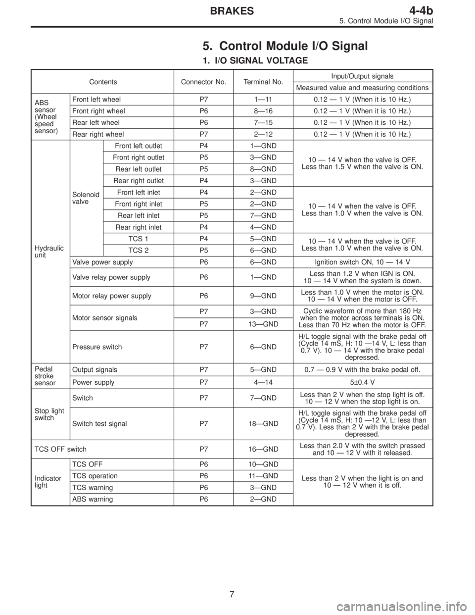
5. Control Module I/O Signal
1. I/O SIGNAL VOLTAGE
Contents Connector No. Terminal No.Input/Output signals
Measured value and measuring conditions
ABS
sensor
(Wheel
speed
sensor)Front left wheel P7 1—11 0.12—1 V (When it is 10 Hz.)
Front right wheel P6 8—16 0.12—1 V (When it is 10 Hz.)
Rear left wheel P6 7—15 0.12—1 V (When it is 10 Hz.)
Rear right wheel P7 2—12 0.12—1 V (When it is 10 Hz.)
Hydraulic
unitSolenoid
valveFront left outlet P4 1—GND
10—14 V when the valve is OFF.
Less than 1.5 V when the valve is ON. Front right outlet P5 3—GND
Rear left outlet P5 8—GND
Rear right outlet P4 3—GND
Front left inlet P4 2—GND
10—14 V when the valve is OFF.
Less than 1.0 V when the valve is ON. Front right inlet P5 2—GND
Rear left inlet P5 7—GND
Rear right inlet P4 4—GND
TCS 1 P4 5—GND
10—14 V when the valve is OFF.
Less than 1.0 V when the valve is ON.
TCS 2 P5 6—GND
Valve power supply P6 6—GND Ignition switch ON, 10—14 V
Valve relay power supply P6 1—GNDLess than 1.2 V when IGN is ON.
10—14 V when the system is down.
Motor relay power supply P6 9—GNDLess than 1.0 V when the motor is ON.
10—14 V when the motor is OFF.
Motor sensor signalsP7 3—GNDCyclic waveform of more than 180 Hz
when the motor across terminals is ON.
Less than 70 Hz when the motor is OFF. P7 13—GND
Pressure switch P7 6—GNDH/L toggle signal with the brake pedal off
(Cycle 14 mS, H: 10—14 V, L: less than
0.7 V). 10—14 V with the brake pedal
depressed.
Pedal
stroke
sensorOutput signals P7 5—GND 0.7—0.9 V with the brake pedal off.
Power supply P7 4—14 5±0.4 V
Stop light
switchSwitch P7 7—GNDLess than 2 V when the stop light is off.
10—12 V when the stop light is on.
Switch test signal P7 18—GNDH/L toggle signal with the brake pedal off
(Cycle 14 mS, H: 10—12 V, L: less than
0.7 V). Less than 2 V with the brake pedal
depressed.
TCS OFF switch P7 16—GNDLess than 2.0 V with the switch pressed
and 10—12 V with it released.
Indicator
lightTCS OFF P6 10—GND
Less than2Vwhenthelight is on and
10—12 V when it is off. TCS operation P6 11—GND
TCS warning P6 3—GND
ABS warning P6 2—GND
7
4-4bBRAKES
5. Control Module I/O Signal
Page 1689 of 2248

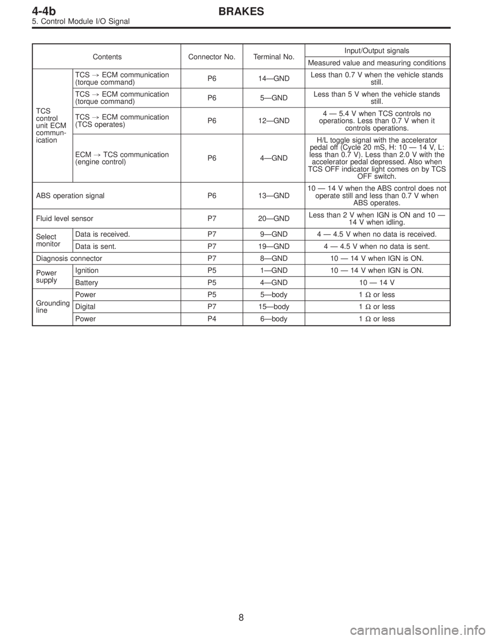
Contents Connector No. Terminal No.Input/Output signals
Measured value and measuring conditions
TCS
control
unit ECM
commun-
icationTCS,ECM communication
(torque command)P6 14—GNDLess than 0.7 V when the vehicle stands
still.
TCS,ECM communication
(torque command)P6 5—GNDLess than 5 V when the vehicle stands
still.
TCS,ECM communication
(TCS operates)P6 12—GND4—5.4 V when TCS controls no
operations. Less than 0.7 V when it
controls operations.
ECM,TCS communication
(engine control)P6 4—GNDH/L toggle signal with the accelerator
pedal off (Cycle 20 mS, H: 10—14 V, L:
less than 0.7 V). Less than 2.0 V with the
accelerator pedal depressed. Also when
TCS OFF indicator light comes on by TCS
OFF switch.
ABS operation signal P6 13—GND10—14 V when the ABS control does not
operate still and less than 0.7 V when
ABS operates.
Fluid level sensor P7 20—GNDLess than2VwhenIGNisONand10—
14 V when idling.
Select
monitorData is received. P7 9—GND 4—4.5 V when no data is received.
Data is sent. P7 19—GND 4—4.5 V when no data is sent.
Diagnosis connector P7 8—GND 10—14 V when IGN is ON.
Power
supplyIgnition P5 1—GND 10—14 V when IGN is ON.
Battery P5 4—GND 10—14 V
Grounding
linePower P5 5—body 1Ωor less
Digital P7 15—body 1Ωor less
Power P4 6—body 1Ωor less
8
4-4bBRAKES
5. Control Module I/O Signal
Page 1697 of 2248

C: INSPECTION MODE
The on-board diagnosis system is designed to detect prob-
lems while the vehicle is being driven. If a problem is found,
the ABS and TCS warning light will illuminate to inform the
driver of the occurrence of a problem. When the warning
light is on, the ABS/TCS system will be inactive and the
normal braking function will work. It is possible for the most
recent trouble code and history of problem to be stored in
memory until cleared.
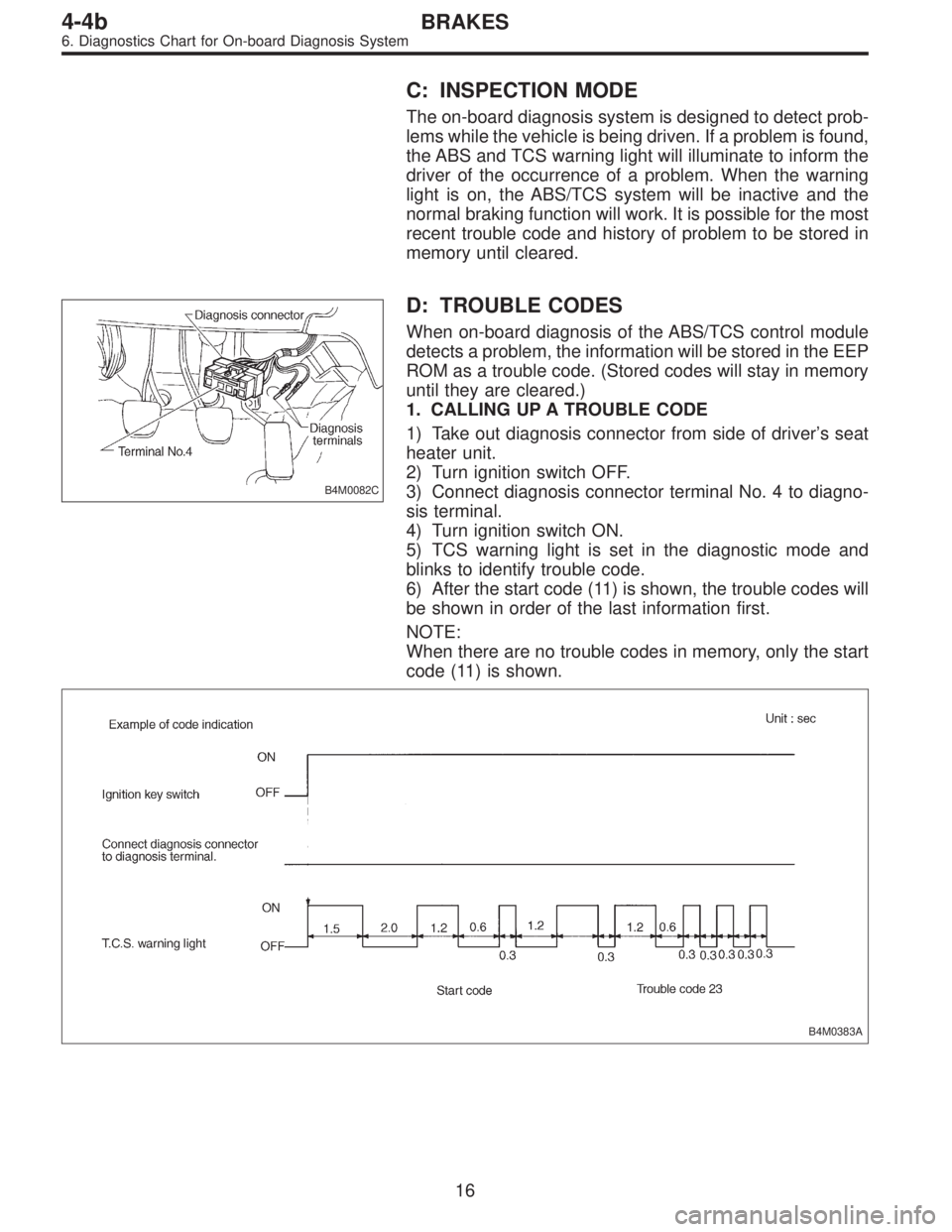
B4M0082C
D: TROUBLE CODES
When on-board diagnosis of the ABS/TCS control module
detects a problem, the information will be stored in the EEP
ROM as a trouble code. (Stored codes will stay in memory
until they are cleared.)
1. CALLING UP A TROUBLE CODE
1) Take out diagnosis connector from side of driver’s seat
heater unit.
2) Turn ignition switch OFF.
3) Connect diagnosis connector terminal No. 4 to diagno-
sis terminal.
4) Turn ignition switch ON.
5) TCS warning light is set in the diagnostic mode and
blinks to identify trouble code.
6) After the start code (11) is shown, the trouble codes will
be shown in order of the last information first.
NOTE:
When there are no trouble codes in memory, only the start
code (11) is shown.
B4M0383A
16
4-4bBRAKES
6. Diagnostics Chart for On-board Diagnosis System
Page 1700 of 2248
B4M0715A
1. CHECK TCS WARNING LIGHT.
1) Turn ignition switch OFF.
2) Disconnect all connectors from ABS/TCS control mod-
ule.
3) Turn ignition switch ON.
4) Measure voltage between ABS/TCS control module
connector and body.
Connector & terminal / Specified voltage:
(P6) No. 3 — body / 10 — 14 V
B4M0387A
2. CHECK DIAGNOSIS TERMINAL.
1) Turn ignition switch OFF.
2) Measure resistance between diagnosis terminal and
body.
Connector/Specified resistance:
B81 — body / 0Ω
B4M0388A
3. CHECK DIAGNOSIS CONNECTOR.
1) Turn ignition switch OFF.
2) Disconnect all connectors from ABS/TCS control mod-
ule.
3) Measure resistance between diagnosis connector and
body.
Connector & terminal / Specified resistance:
(B82) No. 4 — body / 0Ω
19
4-4bBRAKES
7. Diagnostics Chart for Warning Light Circuit Failure
Page 1702 of 2248
1. CHECK BRAKE FLUID LEVEL.
Check that brake fluid level is above the MIN indication on
the reservoir tank.
B4M0716A
2. CHECK BRAKE FLUID LEVEL SENSOR.
1) Turn ignition switch OFF.
2) Disconnect connector from brake fluid level sensor.
Connector & terminal / Specified resistance:
(B16) No. 1—No.2/0Ω(Leaving float where it
is.)
(B16) No. 1—No.2/1MΩ(When pushing float
down.)
B4M0717A
3. CHECK HARNESS CONNECTOR BETWEEN ABS/
TCS CONTROL MODULE AND ALTERNATOR.
1) Turn ignition switch OFF.
2) Connect connector from brake fluid level sensor.
3) Disconnect all connectors from ABS/TCS control mod-
ule.
4) Measure voltage between ABS/TCS control module
connector and body.
Connector & terminal / Specified voltage:
(P7) No. 20—body/2Vorless
5) Start the engine.
6) Measure voltage between ABS/TCS control module
connector and body.
Connector & terminal / Specified voltage:
(P7) No. 20—body / 10—14 V
21
4-4bBRAKES
7. Diagnostics Chart for Warning Light Circuit Failure
Page 1704 of 2248
B4M0393A
1. CHECK HARNESS CONNECTOR BETWEEN ABS/
TCS CONTROL MODULE AND ABS WARNING LIGHT.
1) Turn ignition switch OFF.
2) Disconnect connector from ABS/TCS control module
and TCS valve relay.
3) Measure resistance between ABS/TCS control module
connector and body.
Connector & terminal / Specified resistance:
(P6) No. 2—body/1MΩor more
23
4-4bBRAKES
7. Diagnostics Chart for Warning Light Circuit Failure