Page 1735 of 2248
B4M0405A
1. CHECK GROUND CIRCUIT OF ABS/TCS CONTROL
MODULE.
1) Turn ignition switch OFF.
2) Disconnect connector from ABS/TCS control module.
3) Measure resistance between ABS/TCS control module
connector and body.
Connector & terminal / Specified resistance:
(P4) No. 6—body / 1Ωor less
(P5) No. 5—body / 1Ωor less
(P7) No. 15—body / 1Ωor less
2. CHECK HARNESS CONNECTORS BETWEEN
POWER SUPPLY GENERATOR, BATTERY AND ABS/
TCS CONTROL MODULE.
Check for poor contacts in plug-in connectors. Refer to
“Basic checks”in“FOREWORD”.
54
4-4bBRAKES
8. Diagnostics Chart with Trouble Code
Page 1737 of 2248
B4M0430
1. CHECK GENERATOR.
1) Idling after warm-up.
2) Measure voltage between generator B terminal and
body.
Connector / Specified voltage:
(F25)—body / 10—15 V
2. CHECK BATTERY TERMINAL.
Check that the positive and negative battery terminals are
firmly fixed.
B4M0431A
3. CHECK INPUT VOLTAGE OF ABS/TCS CONTROL
MODULE.
1) Turn ignition switch OFF.
2) Disconnect connector from ABS/TCS control module.
3) Run the engine at idle.
4) Measure voltage between ABS/TCS control module
connector and body.
Connector & terminal / Specified voltage:
(P5) No. 1—body / 10—15 V
B4M0405A
4. CHECK GROUND CIRCUIT OF ABS/TCS CONTROL
MODULE.
1) Turn ignition switch OFF.
2) Disconnect connector from ABS/TCS control module.
3) Measure resistance between ABS/TCS control module
connector and body.
Connector & terminal / Specified resistance:
(P4) No. 6—body / 1Ωor less
(P5) No. 5—body / 1Ωor less
(P7) No. 15—body / 1Ωor less
56
4-4bBRAKES
8. Diagnostics Chart with Trouble Code
Page 1740 of 2248

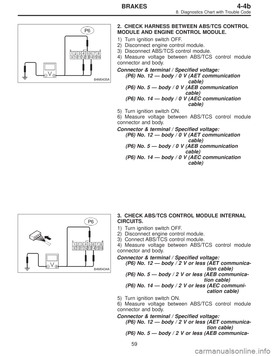
B4M0435A
2. CHECK HARNESS BETWEEN ABS/TCS CONTROL
MODULE AND ENGINE CONTROL MODULE.
1) Turn ignition switch OFF.
2) Disconnect engine control module.
3) Disconnect ABS/TCS control module.
4) Measure voltage between ABS/TCS control module
connector and body.
Connector & terminal / Specified voltage:
(P6) No. 12—body/0V(AET communication
cable)
(P6) No. 5—body/0V(AEB communication
cable)
(P6) No. 14—body/0V(AEC communication
cable)
5) Turn ignition switch ON.
6) Measure voltage between ABS/TCS control module
connector and body.
Connector & terminal / Specified voltage:
(P6) No. 12—body/0V(AET communication
cable)
(P6) No. 5—body/0V(AEB communication
cable)
(P6) No. 14—body/0V(AEC communication
cable)
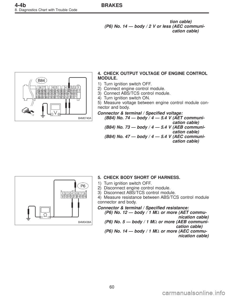
B4M0434A
3. CHECK ABS/TCS CONTROL MODULE INTERNAL
CIRCUITS.
1) Turn ignition switch OFF.
2) Disconnect engine control module.
3) Connect ABS/TCS control module.
4) Measure voltage between ABS/TCS control module
connector and body.
Connector & terminal / Specified voltage:
(P6) No. 12—body/2Vorless (AET communica-
tion cable)
(P6) No. 5—body/2Vorless (AEB communica-
tion cable)
(P6) No. 14—body/2Vorless (AEC communi-
cation cable)
5) Turn ignition switch ON.
6) Measure voltage between ABS/TCS control module
connector and body.
Connector & terminal / Specified voltage:
(P6) No. 12—body/2Vorless (AET communica-
tion cable)
(P6) No. 5—body/2Vorless (AEB communica-
59
4-4bBRAKES
8. Diagnostics Chart with Trouble Code
Page 1741 of 2248

tion cable)
(P6) No. 14—body/2Vorless (AEC communi-
cation cable)
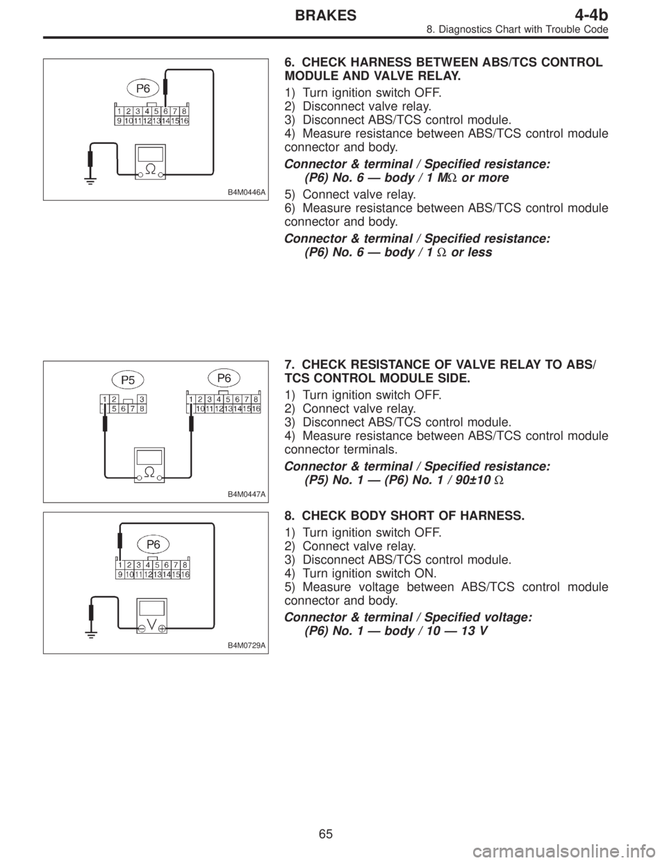
B4M0740A
4. CHECK OUTPUT VOLTAGE OF ENGINE CONTROL
MODULE.
1) Turn ignition switch OFF.
2) Connect engine control module.
3) Connect ABS/TCS control module.
4) Turn ignition switch ON.
5) Measure voltage between engine control module con-
nector and body.
Connector & terminal / Specified voltage:
(B84) No. 74—body / 4—5.4 V (AET communi-
cation cable)
(B84) No. 73—body / 4—5.4 V (AEB communi-
cation cable)
(B84) No. 47—body / 4—5.4 V (AEC communi-
cation cable)
B4M0438A
5. CHECK BODY SHORT OF HARNESS.
1) Turn ignition switch OFF.
2) Disconnect engine control module.
3) Disconnect ABS/TCS control module.
4) Measure resistance between ABS/TCS control module
connector and body.
Connector & terminal / Specified resistance:
(P6) No. 12—body/1MΩor more (AET commu-
nication cable)
(P6) No. 5—body/1MΩor more (AEB communi-
cation cable)
(P6) No. 14—body/1MΩor more (AEC commu-
nication cable)
60
4-4bBRAKES
8. Diagnostics Chart with Trouble Code
Page 1742 of 2248
B4M0728A
6. CHECK OPEN CIRCUIT OF HARNESS.
1) Turn ignition switch OFF.
2) Disconnect engine control module.
3) Disconnect ABS/TCS control module.
4) Measure resistance between ABS/TCS control module
connector and engine control module connector.
(P6) No. 12—(B84) No. 74 / 1Ωor less (AET commu-
nication
cable)
(P6) No. 5—(B84) No. 73 / 1Ωor less (AEB commu-
nication cable)
(P6) No. 14—(B84) No. 47 / 1Ωor less (AEC com-
munication
cable)
61
4-4bBRAKES
8. Diagnostics Chart with Trouble Code
Page 1744 of 2248
B4M0440
B4M0441
1. CHECK RESISTANCE OF VALVE RELAY.
1) Turn ignition switch OFF.
2) Remove valve relay.
3) Measure resistance between valve relay terminals.
Terminal / Specified resistance:
No. A—B / 90±10Ω
B4M0442
2. CHECK CONTACT POINT OF VALVE RELAY.
1) Turn ignition switch OFF.
2) Remove valve relay.
3) Attach circuit tester probes to terminals as shown in
figure.
4) Measure resistance between respective terminals.
Terminal / Specified resistance:
No. C—E/1Ωor less (When 12 volts applied.)
No. C—E/1MΩor more
(When no voltage is applied.)
No. C—F/1MΩor more
(When 12 volts applied.)
No. C—F/1Ωor less
(When no voltage is applied.)
63
4-4bBRAKES
8. Diagnostics Chart with Trouble Code
Page 1745 of 2248
B4M0443
3. CHECK SHORT CIRCUIT OF VALVE RELAY.
1) Turn ignition switch OFF.
2) Remove valve relay.
3) Measure resistance between valve relay terminals.
Terminal / Specified resistance:
No. B—F/1MΩor more
B4M0444A
4. CHECK INPUT VOLTAGE OF VALVE RELAY.
1) Turn ignition switch OFF.
2) Disconnect valve relay.
3) Measure voltage between valve relay connector and
body.
Connector & terminal / Specified voltage:
(F11) No. 1—body/0V
(F11) No. 3—body / 10—13 V
4) Turn ignition switch ON.
5) Measure voltage between valve relay connector and
body.
Connector & terminal / Specified voltage:
(F11) No. 1—body / 10—13 V
(F11) No. 3—body / 10—13 V
B4M0445A
5. CHECK GROUND CIRCUIT OF VALVE RELAY.
1) Turn ignition switch OFF.
2) Disconnect valve relay.
3) Disconnect ABS/TCS control module.
4) Measure resistance between valve relay connector and
body.
Connector & terminal / Specified resistance:
(F11) No. 6—body / 1Ωor less
64
4-4bBRAKES
8. Diagnostics Chart with Trouble Code
Page 1746 of 2248

B4M0446A
6. CHECK HARNESS BETWEEN ABS/TCS CONTROL
MODULE AND VALVE RELAY.
1) Turn ignition switch OFF.
2) Disconnect valve relay.
3) Disconnect ABS/TCS control module.
4) Measure resistance between ABS/TCS control module
connector and body.
Connector & terminal / Specified resistance:
(P6) No. 6—body/1MΩor more
5) Connect valve relay.
6) Measure resistance between ABS/TCS control module
connector and body.
Connector & terminal / Specified resistance:
(P6) No. 6—body / 1Ωor less
B4M0447A
7. CHECK RESISTANCE OF VALVE RELAY TO ABS/
TCS CONTROL MODULE SIDE.
1) Turn ignition switch OFF.
2) Connect valve relay.
3) Disconnect ABS/TCS control module.
4) Measure resistance between ABS/TCS control module
connector terminals.
Connector & terminal / Specified resistance:
(P5) No. 1—(P6) No. 1 / 90±10Ω
B4M0729A
8. CHECK BODY SHORT OF HARNESS.
1) Turn ignition switch OFF.
2) Connect valve relay.
3) Disconnect ABS/TCS control module.
4) Turn ignition switch ON.
5) Measure voltage between ABS/TCS control module
connector and body.
Connector & terminal / Specified voltage:
(P6) No. 1—body / 10—13 V
65
4-4bBRAKES
8. Diagnostics Chart with Trouble Code