Page 1760 of 2248
B4M0743
1. CHECK ENGINE TROUBLE CODE.
1) Read out engine trouble code.
2) Is trouble code 39 in memory?
B4M0395A
2. CHECK INPUT VOLTAGE OF ABS/TCS CONTROL
MODULE.
1) Turn ignition switch OFF.
2) Disconnect ABS/TCS control module connectors.
3) Turn ignition switch ON, while engine is idling.
4) Measure voltage between ABS/TCS control module
connector and body.
Connector & terminal / Specified voltage:
(P5) No. 1—body / 14.5±0.3 V
79
4-4bBRAKES
8. Diagnostics Chart with Trouble Code
Page 1761 of 2248
 Turn ignition switch OFF.
2) Remove No. 18 fuse from fuse and joint box.
3) Disconnect ABS/TCS control module connectors.
4) Measure resistance between AB")
B4M0733A
3. CHECK GROUND SHORT OF HARNESS.
1) Turn ignition switch OFF.
2) Remove No. 18 fuse from fuse and joint box.
3) Disconnect ABS/TCS control module connectors.
4) Measure resistance between ABS/TCS control module
connector and body.
Connector & terminal / Specified resistance:
(P5) No. 1—body/1MΩor more
B4M0405A
4. CHECK GROUND CIRCUIT OF ABS/TCS CONTROL
MODULE.
1) Turn ignition switch OFF.
2) Disconnect connector from ABS/TCS control module.
3) Measure resistance between ABS/TCS control module
connector and body.
Connector & terminal / Specified resistance:
(P4) No. 6—body / 1Ωor less
(P5) No. 5—body / 1Ωor less
(P7) No. 15—body / 1Ωor less
5. CHECK GENERATOR FUNCTION.
1) When the ignition key is at OFF, check the charge warn-
ing light is off.
2) Turn the key ON and ensure the light comes on.
3) Keep the engine running at idle and ensure the light
goes off.
B4M0473A
B4M0395A
6. CHECK INPUT VOLTAGE OF ABS/TCS CONTROL
MODULE.
1) Turn ignition switch OFF.
2) Disconnect ABS/TCS control module connectors.
3) Turn ignition switch ON.
4) Measure voltage between ABS/TCS control module
connector and body.
Connector & terminal / Specified voltage:
(P7) No. 20—body/2Vorless (Engine OFF)
(P7) No. 20—body / 10—14 V (Engine idling)
(P5) No. 1—body / 10—13 V (Engine OFF)
80
4-4bBRAKES
8. Diagnostics Chart with Trouble Code
Page 1763 of 2248
B4M0742
B4M0734A
1. CHECK CONTACT POINT OF PRESSURE SWITCH.
1) Turn ignition switch OFF.
2) Disconnect hydraulic unit connector.
3) Measure resistance between hydraulic unit connector
terminals.
Connector & terminal / Specified resistance:
(F12) No. 1—No.2/1MΩor more (With brake
pedal
depressed)
(F12) No. 1—No.2/1Ωor less (Without brake
pedal depressed)
82
4-4bBRAKES
8. Diagnostics Chart with Trouble Code
Page 1764 of 2248
 Turn ignition switch OFF.
2) Disconnect hydraulic unit connector.
3) Measure resistance between hydraulic unit connector
and body.
Connector & termi")
B4M0735A
2. CHECK BODY SHORT OF PRESSURE SWITCH.
1) Turn ignition switch OFF.
2) Disconnect hydraulic unit connector.
3) Measure resistance between hydraulic unit connector
and body.
Connector & terminal / Specified resistance:
(F12) No. 1—body/1MΩor more
(F12) No. 2—body/1MΩor more
B4M0477A
3. CHECK HARNESS BETWEEN PRESSURE SWITCH
AND ABS/TCS CONTROL MODULE.
1) Turn ignition switch OFF.
2) Connect hydraulic unit connector.
3) Disconnect ABS/TCS control module connector.
4) Measure resistance between ABS/TCS control module
connector terminals.
Connector & terminal / Specified resistance:
(P7) No. 6—No.18/1MΩor more (With brake
pedal
depressed)
(P7) No. 6—No. 18 / 1Ωor less (Without brake
pedal depressed)
B4M0478A
4. CHECK BODY SHORT OF PRESSURE SWITCH
HARNESS.
1) Turn ignition switch OFF.
2) Disconnect ABS/TCS control module connector.
3) Measure resistance between ABS/TCS control module
connector and body.
Connector & terminal / Specified resistance:
(P7) No. 6—body/1MΩor more
(P7) No. 18—body/1MΩor more
B4M0466A
5. CHECK CONTACT POINT OF STOP LIGHT
SWITCH.
1) Turn ignition switch OFF.
2) Disconnect stop light switch connectors.
3) Remove stroke sensor.
4) Measure resistance between stroke sensor terminals.
83
4-4bBRAKES
8. Diagnostics Chart with Trouble Code
Page 1765 of 2248
Specified
resistance
0—2.2±1.0 (0—0.087±0.039) 1 MΩor more
2.2±1.0—18.0±0.5 (0.087±0.039—0.709±0.020) 1Ωor less
NOTE:
Stroke = 0 when the")
Terminal:
No. 2—No. 3
Stroke
Unit: mm (in)Specified
resistance
0—2.2±1.0 (0—0.087±0.039) 1 MΩor more
2.2±1.0—18.0±0.5 (0.087±0.039—0.709±0.020) 1Ωor less
NOTE:
Stroke = 0 when the rod is completely drawn in.
B4M0467A
6. CHECK BODY SHORT OF STOP LIGHT SWITCH.
1) Turn ignition switch OFF.
2) Disconnect stroke sensor connectors.
3) Remove stroke sensor.
4) Measure resistance between stroke sensor terminal
and stroke sensor threads.
Terminal / Specified resistance:
No. 2—stroke sensor threads/1MΩor more
No. 3—stroke sensor threads/1MΩor more
B4M0468A
7. CHECK POWER SUPPLY OF STOP LIGHT
SWITCH.
1) Turn ignition switch OFF.
2) Disconnect stroke sensor connector.
3) Measure voltage between stroke sensor connector and
body.
Connector & terminal / Specified voltage:
(B67) No. 3—body / 10—13 V
B4M0469A
8. CHECK INPUT VOLTAGE OF ABS/TCS CONTROL
MODULE.
1) Turn ignition switch OFF.
2) Install stroke sensor.
3) Connect stroke sensor connector.
4) Disconnect ABS/TCS control module connector.
5) Measure voltage between ABS/TCS control module
connector and body.
Connector & terminal / Specified voltage:
(P7) No. 7—body / 10—13 V (With brake pedal
depressed)
(P7) No. 7—body/0V(Without brake pedal
depressed)
84
4-4bBRAKES
8. Diagnostics Chart with Trouble Code
Page 1769 of 2248
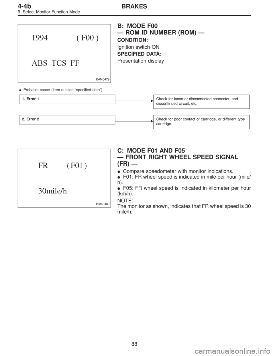
B4M0479
B: MODE F00
—ROM ID NUMBER (ROM)—
CONDITION:
Ignition switch ON
SPECIFIED DATA:
Presentation display
�Probable cause (Item outside“specified data”)
1. Error 1
�Check for loose or disconnected connector, and
discontinued circuit, etc.
2. Error 2�Check for poor contact of cartridge, or different type
cartridge.
B4M0480
C: MODE F01 AND F05
—FRONT RIGHT WHEEL SPEED SIGNAL
(FR)—
�Compare speedometer with monitor indications.
�F01: FR wheel speed is indicated in mile per hour (mile/
h).
�F05: FR wheel speed is indicated in kilometer per hour
(km/h).
NOTE:
The monitor as shown, indicates that FR wheel speed is 30
mile/h.
88
4-4bBRAKES
9. Select Monitor Function Mode
Page 1818 of 2248

B5M0115B
B: ON-BOARD DIAGNOSTIC
When the airbag system is in functioning condition, the
airbag warning light will remain on for 8 seconds and go out
when the ignition switch is set to ON.
If there is any malfunction, the airbag warning light will
either stay on or off continuously. In such cases, perform
on-board diagnostic in accordance with the specified pro-
cedure to determine trouble codes.
1) Turn ignition switch ON (with engine OFF).
2) Connect DIAG. terminal�
1to No. 1 terminal of diagno-
sis connector�
2located below lower cover.
3) Check in accordance with the trouble code indicated by
the AIRBAG warning light, and record the trouble codes.
4) Turn the ignition switch “OFF” and remove the DIAG.
terminal from No.1 terminal of diagnosis connector.
B5M0116B
C: CLEAR MEMORY
After eliminating problem as per trouble code, clear
memory as follows:
Make sure ignition switch is ON (and engine off). Connect
one DIAG. terminal�
1on diagnosis connector�2terminal
No. 1.
While warning light is flashing, connect the other DIAG.
terminal�
3on terminal No. 2 for at least three seconds.
After memory is cleared, normal warning light flashing rate
resumes. (Warning light flashes every 0.6 seconds ON-
OFF operation.) Memory cannot be cleared if any problem
exists.
After clear memory and then DIAG. terminals�
1and�3,
extract from diagnosis connector�
2.
9
5-5SUPPLEMENTAL RESTRAINT SYSTEM
4. Diagnostics Chart for On-board Diagnostic System
Page 1821 of 2248
![SUBARU LEGACY 1995 Service Repair Manual E: DIAGNOSTICS PROCEDURE
Airbag warning light stays on after 8 seconds.
1) Perform on-board diagnostic. <Ref. to 5-5 [T4B0].>
2) Are trouble codes 2, 4, 12, 13, 22, 23, 24 or 32 indicated? <Ref. to 5-](/manual-img/17/57432/w960_57432-1820.png "SUBARU LEGACY 1995 Service Repair Manual E: DIAGNOSTICS PROCEDURE
Airbag warning light stays on after 8 seconds.
1) Perform on-board diagnostic. <Ref. to 5-5 [T4B0].>
2) Are trouble codes 2, 4, 12, 13, 22, 23, 24 or 32 indicated? <Ref. to 5-")
E: DIAGNOSTICS PROCEDURE
Airbag warning light stays on after 8 seconds.
1) Perform on-board diagnostic.
2) Are trouble codes 2, 4, 12, 13, 22, 23, 24 or 32 indicated?
Record trouble codes.
3) If“NO”, proceed with diagnostics and repair according to trouble code indicated then perform step 29).
4) If“YES”, proceed by turning ignition switch“OFF”, disconnect battery ground cable, and wait 20 seconds. If codes 12 or 13 are
indicated proceed to step 5). If codes 12 or 13 are not indicated proceed to step 6).
5) Remove driver side airbag module and connect test harness C
connector (1C) to (AB7).
Connect airbag resistor to test harness C connector (3C). Pro-
ceed to step 19).
G5M0430
6) If codes 4 or 22 are indicated, proceed to step 7). If codes 4 or 22 are not indicated proceed to step 11).
7) Turn ignition switch“OFF”, disconnect battery ground cable,
and wait 20 seconds. Disconnect passenger side airbag mod-
ule connector (AB9) to (AB10). Connect
test harness C connector (1C) to (AB9).
Connect airbag resistor to test harness C connector (3C).
B5M0118A
8) Reconnect battery ground cable and turn ignition switch“ON”, does airbag warning light go out after 8 seconds and remain“OFF”
for more than 30 seconds? See notes 1) and 2). (Refer to end of chart.)
9) If“YES”, turn ignition switch“OFF”, disconnect battery ground cable, and wait 20 seconds. Install a new passenger side airbag
module then proceed to step 29).
10) If“NO”proceed to step 1).
11) Remove lower cover panel and connect test harness C con-
nector (1C) to (AB8) with airbag resis-
tor attached to test harness C connector (3C).
Turn ignition switch“ON”. Does airbag warning light go“OFF”
after 8 seconds and remain off for more than 30 seconds?
See notes 1) and 2). (Refer to end of chart.)
If“YES”proceed to step 5).
If“NO”proceed to step 12).
G5M0429
12
5-5SUPPLEMENTAL RESTRAINT SYSTEM
4. Diagnostics Chart for On-board Diagnostic System
 Read out engine trouble code.
2) Is trouble code 39 in memory?
B4M0395A
2. CHECK INPUT VOLTAGE OF ABS/TCS CONTROL
MODULE.
1) Turn ignition switch OFF.
2) Disco")
 Turn ignition switch OFF.
2) Disconnect hydraulic unit connector.
3) Measure resistance between hydraulic unit connector
terminals.
Conne")