Page 1444 of 2248
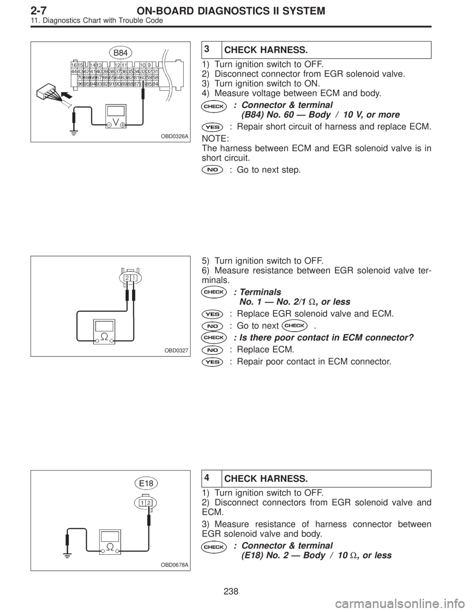
OBD0326A
3
CHECK HARNESS.
1) Turn ignition switch to OFF.
2) Disconnect connector from EGR solenoid valve.
3) Turn ignition switch to ON.
4) Measure voltage between ECM and body.
: Connector & terminal
(B84) No. 60—Body / 10 V, or more
: Repair short circuit of harness and replace ECM.
NOTE:
The harness between ECM and EGR solenoid valve is in
short circuit.
: Go to next step.
OBD0327
5) Turn ignition switch to OFF.
6) Measure resistance between EGR solenoid valve ter-
minals.
: Terminals
No. 1—No. 2/1Ω, or less
: Replace EGR solenoid valve and ECM.
: Go to next.
: Is there poor contact in ECM connector?
: Replace ECM.
: Repair poor contact in ECM connector.
OBD0678A
4
CHECK HARNESS.
1) Turn ignition switch to OFF.
2) Disconnect connectors from EGR solenoid valve and
ECM.
3) Measure resistance of harness connector between
EGR solenoid valve and body.
: Connector & terminal
(E18) No. 2—Body / 10Ω, or less
238
2-7ON-BOARD DIAGNOSTICS II SYSTEM
11. Diagnostics Chart with Trouble Code
Page 1445 of 2248
: Repair short circuit of harness between ECM con-
nector and EGR solenoid valve connector.
: Go to the next step.
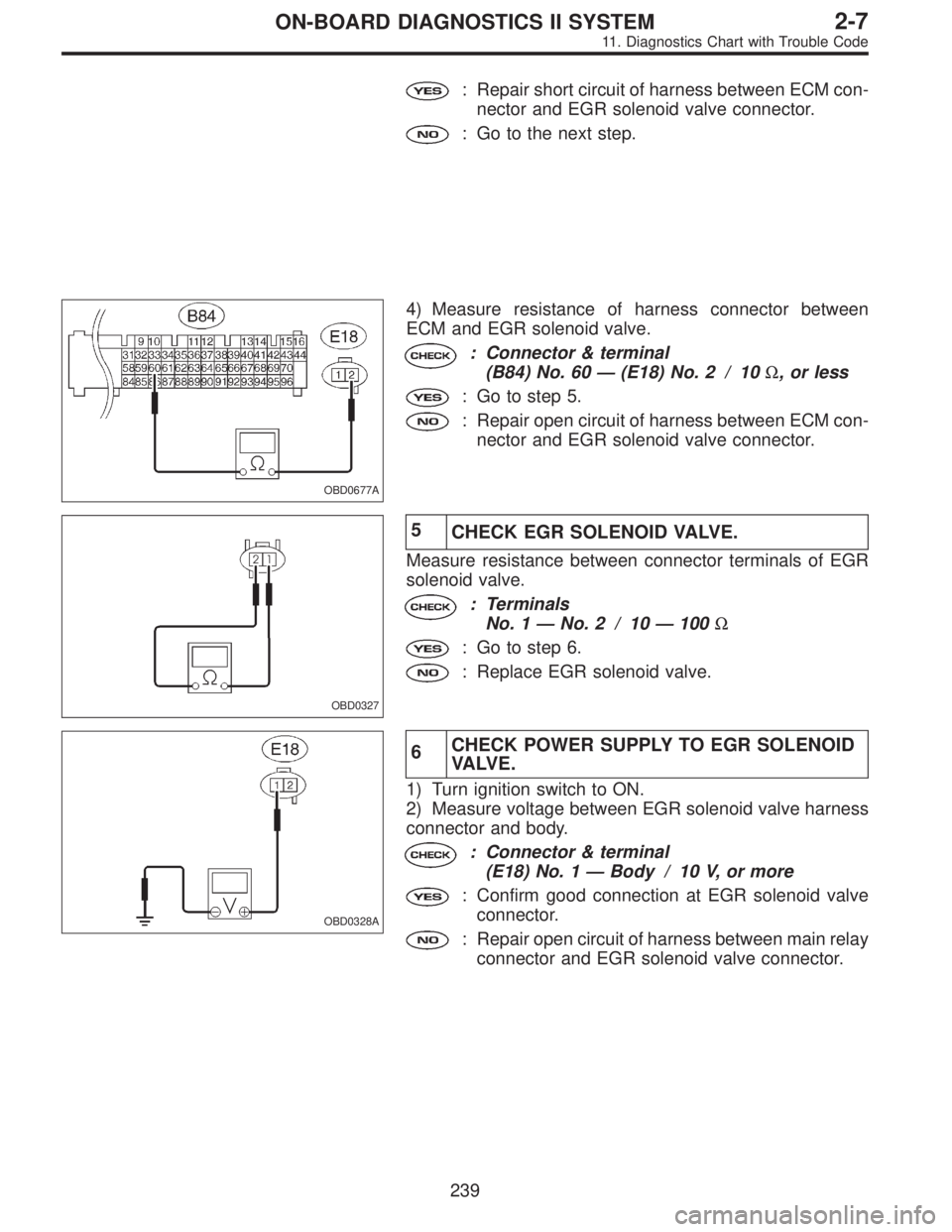
OBD0677A
4) Measure resistance of harness connector between
ECM and EGR solenoid valve.
: Connector & terminal
(B84) No. 60—(E18) No. 2 / 10Ω, or less
: Go to step 5.
: Repair open circuit of harness between ECM con-
nector and EGR solenoid valve connector.
OBD0327
5
CHECK EGR SOLENOID VALVE.
Measure resistance between connector terminals of EGR
solenoid valve.
: Terminals
No. 1—No. 2 / 10—100Ω
: Go to step 6.
: Replace EGR solenoid valve.
OBD0328A
6CHECK POWER SUPPLY TO EGR SOLENOID
VA LV E .
1) Turn ignition switch to ON.
2) Measure voltage between EGR solenoid valve harness
connector and body.
: Connector & terminal
(E18) No. 1—Body / 10 V, or more
: Confirm good connection at EGR solenoid valve
connector.
: Repair open circuit of harness between main relay
connector and EGR solenoid valve connector.
239
2-7ON-BOARD DIAGNOSTICS II SYSTEM
11. Diagnostics Chart with Trouble Code
Page 1453 of 2248
1
CHECK TRANSMISSION TYPE.
Refer to flow chart on page 245.
2CHECK ANY OTHER DTC P0105, P0106,
P0443 AND P1102 ON DISPLAY.
: Check that Subaru select monitor or the
OBD-II general scan tool shows P0105,
P0106, P0443 and P1102.
: Inspect the relevant DTC using“11. Diagnostics
chart with Trouble Code”.
: Go to step 3.
3CHECK PURGE CONTROL SOLENOID VALVE
OPERATION.
1) Turn ignition switch to OFF.
2) Connect test mode connector at the lower portion of
instrument panel (on the driver’s side), to the side of the
center console box.
3) Turn ignition switch to ON.
: Make sure that the ON/OFF operating sound
of purge control solenoid valve occurs at
about 0.3 Hz.
: Replace purge control solenoid valve.
: Go to next step.
4) Disconnect canister purge hose from canister.
: Blow through the canister purge hose to
check if pulsations occur.
: Check and repair loose connections, cracks, and
clogging in evaporation line.
: Replace purge control solenoid valve.
247
2-7ON-BOARD DIAGNOSTICS II SYSTEM
11. Diagnostics Chart with Trouble Code
Page 1456 of 2248
OBD0337A
1
CHECK OUTPUT SIGNAL FROM ECM.
1) Turn ignition switch to ON.
2) Measure voltage between ECM connector terminal and
body.
: Connector & terminal
(B84) No. 59—Body / 10 V, or more
: Go to step 2.
: Go to step 3.
OBD0337A
2
CHECK HARNESS.
1) Turn ignition switch to OFF.
2) Disconnect connector from purge control solenoid
valve.
3) Turn ignition switch to ON.
4) Measure voltage between ECM connector and body.
: Connector & terminal
(B84) No. 59—Body / 10 V, or more
: Repair short circuit of harness between ECM con-
nector and purge control solenoid valve connec-
tor.
: Go to next step.
OBD0338
5) Turn ignition switch to OFF.
6) Measure resistance between purge control solenoid
valve terminals .
: Terminals
No. 1—No. 2/1Ω, or less
: Replace purge control solenoid valve and ECM.
: Go to next.
: Is there poor contact in ECM connector?
: Repair poor contact in ECM connector.
: Replace ECM.
250
2-7ON-BOARD DIAGNOSTICS II SYSTEM
11. Diagnostics Chart with Trouble Code
Page 1457 of 2248
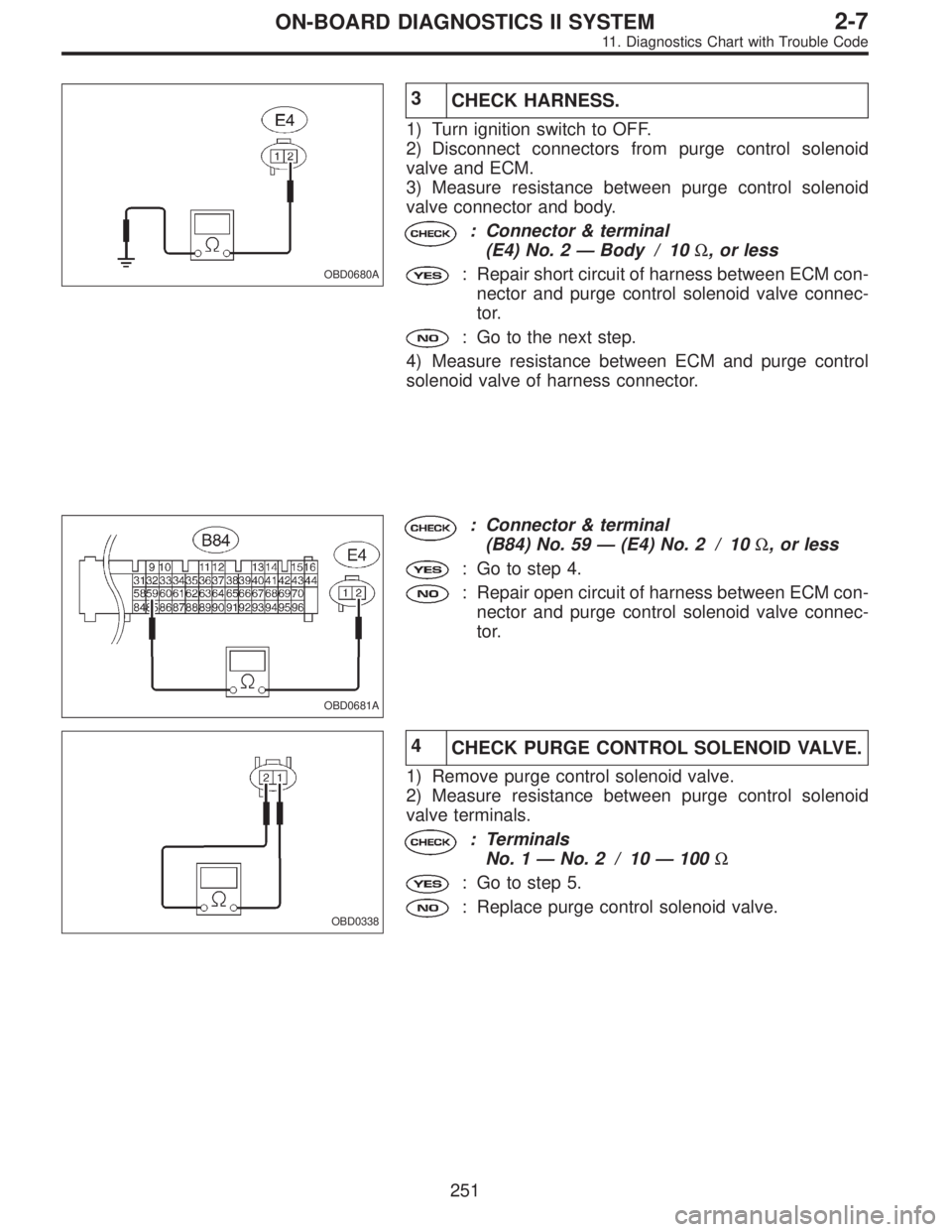
OBD0680A
3
CHECK HARNESS.
1) Turn ignition switch to OFF.
2) Disconnect connectors from purge control solenoid
valve and ECM.
3) Measure resistance between purge control solenoid
valve connector and body.
: Connector & terminal
(E4) No. 2—Body / 10Ω, or less
: Repair short circuit of harness between ECM con-
nector and purge control solenoid valve connec-
tor.
: Go to the next step.
4) Measure resistance between ECM and purge control
solenoid valve of harness connector.
OBD0681A
: Connector & terminal
(B84) No. 59—(E4) No. 2 / 10Ω, or less
: Go to step 4.
: Repair open circuit of harness between ECM con-
nector and purge control solenoid valve connec-
tor.
OBD0338
4
CHECK PURGE CONTROL SOLENOID VALVE.
1) Remove purge control solenoid valve.
2) Measure resistance between purge control solenoid
valve terminals.
: Terminals
No. 1—No. 2 / 10—100Ω
: Go to step 5.
: Replace purge control solenoid valve.
251
2-7ON-BOARD DIAGNOSTICS II SYSTEM
11. Diagnostics Chart with Trouble Code
Page 1458 of 2248
OBD0339A
5CHECK POWER SUPPLY TO PURGE CON-
TROL SOLENOID VALVE.
1) Turn ignition switch to ON.
2) Measure voltage between purge control solenoid valve
connector and body.
: Connector & terminal
(E4) No. 1—Body / 10 V, or more
: Confirm good connection at purge control sole-
noid valve connector.
: Repair open circuit of harness between main relay
connector and purge control solenoid valve con-
nector.
252
2-7ON-BOARD DIAGNOSTICS II SYSTEM
11. Diagnostics Chart with Trouble Code
Page 1461 of 2248
![SUBARU LEGACY 1995 Service Repair Manual 1CHECK SPEEDOMETER OPERATION IN COM-
BINATION METER.
: Check normal operation of speedometer.
: Check speedometer and vehicle speed sensor
<Ref. to 6-2 [K3A0].>.
: Go to step 2.
OBD0349A
2
CHECK HARNE SUBARU LEGACY 1995 Service Repair Manual 1CHECK SPEEDOMETER OPERATION IN COM-
BINATION METER.
: Check normal operation of speedometer.
: Check speedometer and vehicle speed sensor
<Ref. to 6-2 [K3A0].>.
: Go to step 2.
OBD0349A
2
CHECK HARNE](/manual-img/17/57432/w960_57432-1460.png)
1CHECK SPEEDOMETER OPERATION IN COM-
BINATION METER.
: Check normal operation of speedometer.
: Check speedometer and vehicle speed sensor
.
: Go to step 2.
OBD0349A
2
CHECK HARNESS.
1) Turn ignition switch to OFF.
2) Disconnect connector from TCM.
3) Turn ignition switch to ON.
4) Measure voltage between ECM and body.
: Connector & terminal
(B84) No. 57—Body / 2 V, or more
: Check the following and repair if necessary.
�Open circuit of harness between ECM connector and
combination meter connector
�Poor contact in ECM connector
�Poor contact in combination meter connector
�Poor contact in coupling connector (B37)
: Go to step 3.
OBD0351A
3
CHECK HARNESS.
1) Turn ignition switch to OFF.
2) Disconnect connector from ECM.
3) Measure resistance of harness between ECM connec-
tor and body.
: Connector & terminal
(B84) No. 57—Body / 10Ω, or less
: Repair short circuit of harness between ECM con-
nector and combination meter connector.
: Repair poor contact in ECM connector.
255
2-7ON-BOARD DIAGNOSTICS II SYSTEM
11. Diagnostics Chart with Trouble Code
Page 1465 of 2248
1
CHECK AIR INTAKE SYSTEM.
1) Turn ignition switch to ON.
2) Start engine, and idle it.
3) Check intake manifold, idle air control solenoid valve
and throttle body for loose installation and gasket for
cracks.
4) Check by-pass hoses for loose connections and cracks.
5) Check vacuum hoses for disconnections.
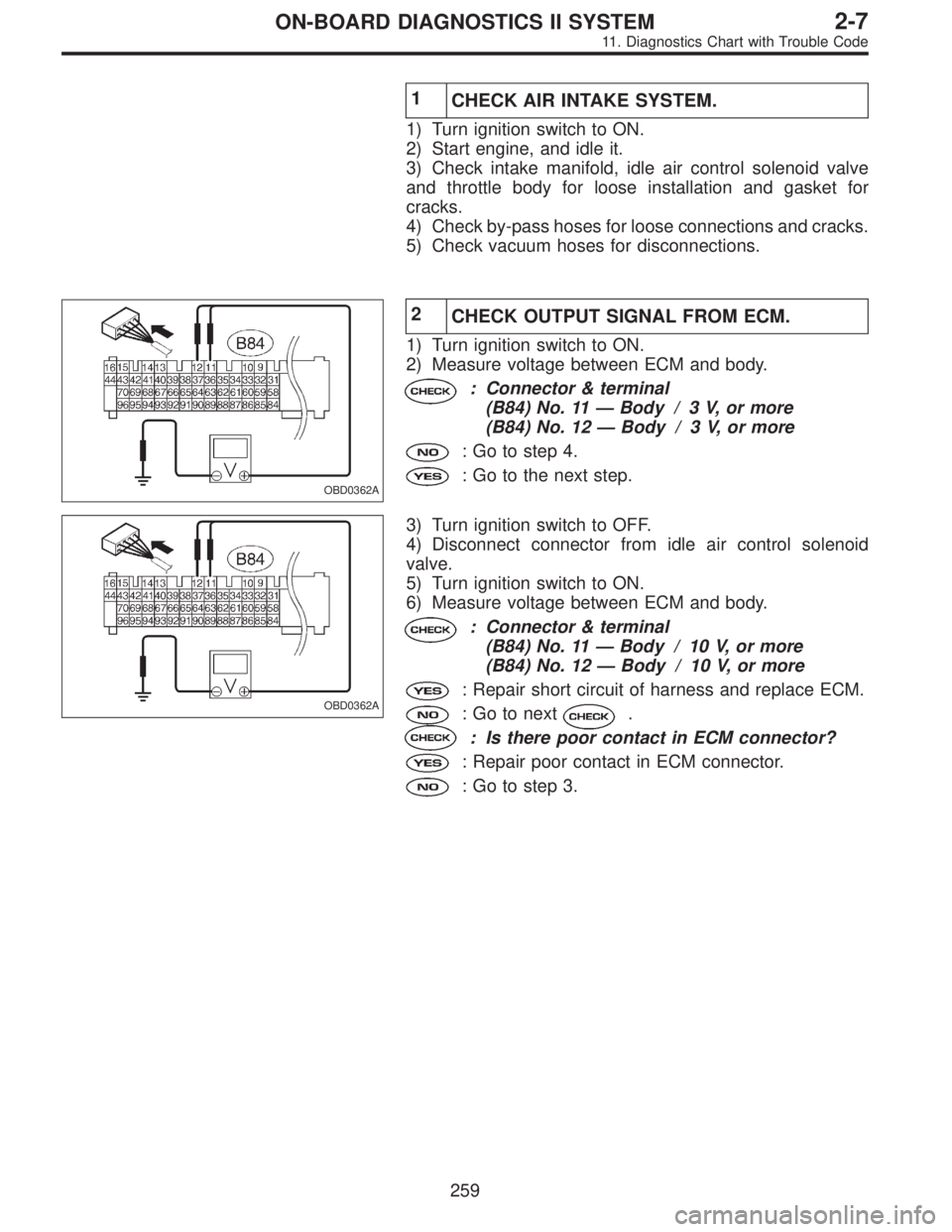
OBD0362A
2
CHECK OUTPUT SIGNAL FROM ECM.
1) Turn ignition switch to ON.
2) Measure voltage between ECM and body.
: Connector & terminal
(B84) No. 11—Body / 3 V, or more
(B84) No. 12—Body / 3 V, or more
: Go to step 4.
: Go to the next step.
OBD0362A
3) Turn ignition switch to OFF.
4) Disconnect connector from idle air control solenoid
valve.
5) Turn ignition switch to ON.
6) Measure voltage between ECM and body.
: Connector & terminal
(B84) No. 11—Body / 10 V, or more
(B84) No. 12—Body / 10 V, or more
: Repair short circuit of harness and replace ECM.
: Go to next.
: Is there poor contact in ECM connector?
: Repair poor contact in ECM connector.
: Go to step 3.
259
2-7ON-BOARD DIAGNOSTICS II SYSTEM
11. Diagnostics Chart with Trouble Code