Page 1516 of 2248
1
CHECK OPERATION OF STARTER MOTOR.
: Turn ignition switch to“ST”to ensure that
starter motor operates.
NOTE:
�On AT vehicles, place the inhibitor switch in the“P”or“N”
position.
�On MT vehicles, depress the clutch pedal.
: Diagnose starter motor circuit
: Repair open circuit or poor contact in ECM con-
nector.
310
2-7ON-BOARD DIAGNOSTICS II SYSTEM
11. Diagnostics Chart with Trouble Code
Page 1518 of 2248
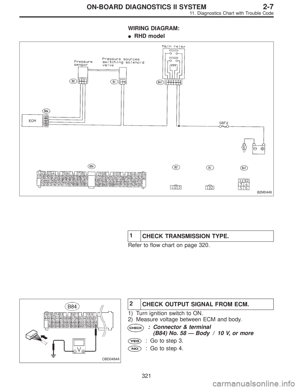
WIRING DIAGRAM:
OBD0467
OBD0468A
1
CHECK INPUT SIGNAL FOR ECM.
1) Turn ignition switch to ON.
2) Measure voltage between ECM and body.
: Connector & terminal
(B84) No. 78—Body / 5.0±0.5 V (Neutral
position)
(B84) No. 78—Body / 0 V (Other positions)
: Go to next.
: Go to step 2.
: Is there poor contact in ECM connector?
: Repair poor contact in ECM connector.
: Replace ECM with a new one.
312
2-7ON-BOARD DIAGNOSTICS II SYSTEM
11. Diagnostics Chart with Trouble Code
Page 1519 of 2248
 Turn ignition switch to OFF.
2) Disconnect connector from transmission harness.
3) Measure resistance between connector terminals of
transmission harness.")
OBD0469A
2
CHECK NEUTRAL POSITION SWITCH.
1) Turn ignition switch to OFF.
2) Disconnect connector from transmission harness.
3) Measure resistance between connector terminals of
transmission harness.
: Connector & terminal
(T2) No. 1—No. 2 / 1 MΩ, or more (Neutral
position)
(T2) No. 1—No. 2 / 10Ω, or less (Other
positions)
: Go to step 3.
: Repair transmission harness or replace neutral
position switch.
OBD0470A
3CHECK HARNESS CONNECTOR BETWEEN
ECM AND NEUTRAL POSITION SWITCH.
1) Disconnect connector from ECM.
2) Measure resistance of harness connector between
ECM and neutral position switch.
: Connector & terminal
(B84) No. 78—(B25) No. 1 / 10Ω, or less
: Repair open circuit of harness between ECM con-
nector and neutral position switch connector.
: Go to next step.
OBD0471A
3) Measure resistance of harness connector between
ECM and body to make sure that circuit does not short.
: Connector & terminal
(B84) No. 78—Body / 1 MΩ, or more
: Repair short circuit of harness between ECM con-
nector and neutral position switch connector.
: Go to next step.
313
2-7ON-BOARD DIAGNOSTICS II SYSTEM
11. Diagnostics Chart with Trouble Code
Page 1522 of 2248
WIRING DIAGRAM:
B2M0629
OBD0468A
1
CHECK INPUT SIGNAL FOR ECM.
1) Turn ignition switch to ON.
2) Measure voltage between ECM and body.
: Connector & terminal
(B84) No. 78—Body / 0 V (“N”and“P”
positions)
(B84) No. 78—Body / 5.0±0.5 V
(Other positions)
Go to next.
: Go to step 2.
: Is there poor contact in ECM connector?
: Repair poor contact in ECM connector.
: Replace ECM with a new one.
316
2-7ON-BOARD DIAGNOSTICS II SYSTEM
11. Diagnostics Chart with Trouble Code
Page 1523 of 2248
OBD0477A
2CHECK HARNESS CONNECTOR BETWEEN
ECM AND INHIBITOR SWITCH.
1) Turn ignition switch to OFF.
2) Disconnect connectors from ECM and transmission.
3) Measure resistance of harness connector between
ECM and transmission.
: Connector & terminal
(B84) No. 78—(B12) No. 12 / 10Ω, or less
: Repair open circuit of harness between ECM con-
nector and transmission connector.
: Go to next step.
OBD0471A
4) Measure resistance of harness connector between
ECM and body.
: Connector & terminal
(B84) No. 78—Body / 1 MΩ, or more
: Repair short circuit of harness between ECM con-
nector and transmission connector.
: Go to next step.
OBD0479A
5) Measure resistance of harness connector between
inhibitor switch and body.
: Connector & terminal
(B12) No. 11—Body / 10Ω, or less
: Go to step 3.
: Repair open circuit of inhibitor switch ground line.
317
2-7ON-BOARD DIAGNOSTICS II SYSTEM
11. Diagnostics Chart with Trouble Code
Page 1527 of 2248
WIRING DIAGRAM:
�RHD model
B2M0449
1
CHECK TRANSMISSION TYPE.
Refer to flow chart on page 320.
OBD0484A
2
CHECK OUTPUT SIGNAL FROM ECM.
1) Turn ignition switch to ON.
2) Measure voltage between ECM and body.
: Connector & terminal
(B84) No. 58—Body / 10 V, or more
: Go to step 3.
: Go to step 4.
321
2-7ON-BOARD DIAGNOSTICS II SYSTEM
11. Diagnostics Chart with Trouble Code
Page 1528 of 2248
OBD0484A
3
CHECK HARNESS CONNECTOR.
1) Turn ignition switch to OFF.
2) Disconnect connector from pressure sources switching
solenoid valve.
3) Turn ignition switch to ON.
4) Measure voltage between ECM and body.
: Connector & terminal
(B84) No. 58—Body / 10 V, or more
: Repair short circuit of harness between ECM con-
nector and pressure sources switching solenoid
valve connector and replace ECM.
: Go to next step.
OBD0485
5) Turn ignition switch to OFF.
6) Measure resistance between pressure sources switch-
ing solenoid valve terminals.
: Terminals
No. 1—No. 2/1Ω, or less
: Replace pressure sources switching solenoid
valve and ECM.
: Go to next.
: Is there poor contact in ECM connector?
: Repair poor contact in ECM connector.
: Replace ECM with a new one.
322
2-7ON-BOARD DIAGNOSTICS II SYSTEM
11. Diagnostics Chart with Trouble Code
Page 1529 of 2248
 Turn ignition switch to OFF.
2) Disconnect connector from pressure sources switching
solenoid valve and ECM.
3) Measure resistance of harness connector between
p")
OBD0488A
4
CHECK HARNESS CONNECTOR.
1) Turn ignition switch to OFF.
2) Disconnect connector from pressure sources switching
solenoid valve and ECM.
3) Measure resistance of harness connector between
pressure sources switching solenoid valve and body.
: Connector & terminal
(B1) No. 1—Body / 10Ω, or less
: Repair short circuit of harness between ECM con-
nector and pressure sources switching solenoid
valve connector.
: Go to next step.
OBD0685A
4) Measure resistance of harness connector between
ECM and pressure sources switching solenoid valve.
: Connector & terminal
(B84) No. 58—(B1) No. 1 / 10Ω, or less
: Go to step 5.
: Repair open circuit of harness between ECM con-
nector and pressure sources switching solenoid
valve connector.
OBD0485
5CHECK PRESSURE SOURCES SWITCHING
SOLENOID VALVE.
Measure resistance between pressure sources switching
solenoid valve connector terminals.
: Terminals
No. 1—No. 2 / 10—100Ω
: Go to step 6.
: Replace pressure sources switching solenoid
valve.
323
2-7ON-BOARD DIAGNOSTICS II SYSTEM
11. Diagnostics Chart with Trouble Code
 Turn ignition switch to ON.
2) Measure voltage between ECM and body.
: Connector & terminal
(B84) No. 78—Body / 5.0±0.5 V (Neutral")
 Turn ignition switch to ON.
2) Measure voltage between ECM and body.
: Connector & terminal
(B84) No. 78—Body / 0 V (“N”and“P�")
 Turn ignition switch to OFF.
2) Disconnect connectors from ECM and transmission.
3) Measure resistance of harness connector betwe")
 Turn ignition switch to OFF.
2) Disconnect connector from pressure sources switching
solenoid valve.
3) Turn ignition switch to ON.
4) Measure voltage between EC")