Page 1466 of 2248
OBD0366
3CHECK IDLE AIR CONTROL SOLENOID
VA LV E .
1) Turn ignition switch to OFF.
2) Measure resistance between solenoid valve terminals.
: Terminals
No. 1—No. 2 / 20Ω, or more
No. 2—No. 3 / 20Ω, or more
: Replace idle air control solenoid valve.
: Go to next.
: Terminals
No. 1—No. 2 / 5Ω, or less
No. 2—No. 3 / 5Ω, or less
: Replace idle air control solenoid valve and ECM.
: Go to next step.
OBD0683
3) Remove idle air control solenoid valve.
[W12A0].>
4) Check operation of idle air control solenoid valve.
: When connecting the battery to terminals
No. 1 and No. 2 of idle air control solenoid
valve, check if it is fully opened.
: Go to next.
: Clean idle air control solenoid valve.
[W12B0].>
OBD0684
: When connecting the battery to terminals
No. 3 and No. 2 of idle air control solenoid
valve, check if it is fully closed.
: Go to step 4.
: Clean idle air control solenoid valve.
[W12B0].>
260
2-7ON-BOARD DIAGNOSTICS II SYSTEM
11. Diagnostics Chart with Trouble Code
Page 1467 of 2248
 Turn ignition switch to OFF.
2) Disconnect connector from idle air control solenoid
valve.
3) Turn ignition switch to ON.
4) Measu")
B2M0253A
4CHECK POWER SUPPLY TO IDLE AIR CON-
TROL SOLENOID VALVE.
1) Turn ignition switch to OFF.
2) Disconnect connector from idle air control solenoid
valve.
3) Turn ignition switch to ON.
4) Measure voltage between idle air control solenoid valve
and body.
: Connector & terminal
(E7) No. 2—Body / 10 V, or more
: Go to step 5.
: Repair open circuit of harness between idle air
control solenoid valve connector and ECM con-
nector.
OBD0368A
5CHECK HARNESS CONNECTOR BETWEEN
ECM AND IDLE AIR CONTROL SOLENOID
VA LV E .
1) Turn ignition switch to OFF.
2) Disconnect connector from ECM.
3) Measure resistance of harness connector between
ECM and idle air control solenoid valve.
: Connector & terminal
(B84) No. 11—(E7) No. 3 / 10Ω, or less
(B84) No. 12—(E7) No. 1 / 10Ω, or less
: Repair open circuit of harness between ECM con-
nector and idle air control solenoid valve connec-
tor.
: Go to the next step.
OBD0369A
4) Measure resistance of harness connector between
ECM and body to make sure that circuit does not short.
: Connector & terminal
(B84) No. 11—Body / 1 MΩ, or more
(B84) No. 12—Body / 1 MΩ, or more
: Confirm good condition in connectors of idle air
control solenoid valve circuit.
: Repair short circuit of harness between ECM con-
nector and idle air control solenoid valve connec-
tor.
261
2-7ON-BOARD DIAGNOSTICS II SYSTEM
11. Diagnostics Chart with Trouble Code
Page 1469 of 2248
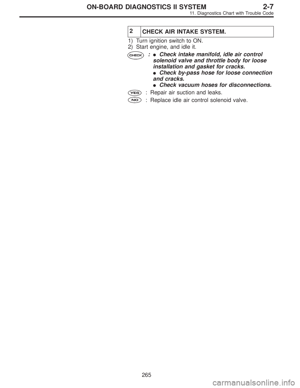
2
CHECK AIR INTAKE SYSTEM.
1) Turn ignition switch to ON.
2) Start engine, and idle it.
: Is clogging the by-pass line between by-
pass hose and intake duct?
: Repair the by-pass line.
: Replace idle air control solenoid valve.
263
2-7ON-BOARD DIAGNOSTICS II SYSTEM
11. Diagnostics Chart with Trouble Code
Page 1471 of 2248
2
CHECK AIR INTAKE SYSTEM.
1) Turn ignition switch to ON.
2) Start engine, and idle it.
:�Check intake manifold, idle air control
solenoid valve and throttle body for loose
installation and gasket for cracks.
�Check by-pass hose for loose connection
and cracks.
�Check vacuum hoses for disconnections.
: Repair air suction and leaks.
: Replace idle air control solenoid valve.
265
2-7ON-BOARD DIAGNOSTICS II SYSTEM
11. Diagnostics Chart with Trouble Code
Page 1473 of 2248
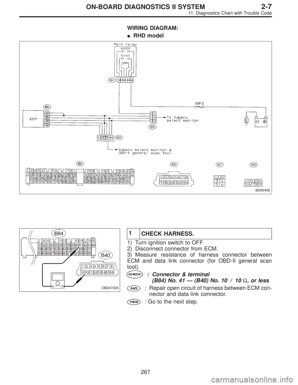
WIRING DIAGRAM:
�RHD model
B2M0458
OBD0722A
1
CHECK HARNESS.
1) Turn ignition switch to OFF.
2) Disconnect connector from ECM.
3) Measure resistance of harness connector between
ECM and data link connector (for OBD-II general scan
tool).
: Connector & terminal
(B84) No. 41—(B40) No. 10 / 10Ω, or less
: Repair open circuit of harness between ECM con-
nector and data link connector.
: Go to the next step.
267
2-7ON-BOARD DIAGNOSTICS II SYSTEM
11. Diagnostics Chart with Trouble Code
Page 1482 of 2248
 Turn ignition switch to OFF.
2) Disconnect connectors from TCM and transmission.
3) Measure resistance of harness connector betwe")
OBD0596A
1CHECK HARNESS CONNECTOR BETWEEN
TCM AND INHIBITOR SWITCH.
1) Turn ignition switch to OFF.
2) Disconnect connectors from TCM and transmission.
3) Measure resistance of harness connector between
TCM and transmission.
: Connector & terminal
(B56) No. 9—(B12) No. 3 / 1Ω, or less
(B56) No. 10—(B12) No. 2 / 1Ω, or less
(B56) No. 8—(B12) No. 1 / 1Ω, or less
(B54) No. 1—(B12) No. 8 / 1Ω, or less
(B54) No. 2—(B12) No. 7 / 1Ω, or less
(B54) No. 3—(B12) No. 6 / 1Ω, or less
(B54) No. 4—(B12) No. 5 / 1Ω, or less
: Repair open circuit of harness between TCM and
transmission.
: Go to next step.
OBD0597A
4) Measure resistance of harness connector between
TCM and body.
: Connector & terminal
(B56) No. 9—Body / 1 MΩ, or more
(B56) No. 10—Body / 1 MΩ, or more
(B56) No. 8—Body / 1 MΩ, or more
(B54) No. 1—Body / 1 MΩ, or more
(B54) No. 2—Body / 1 MΩ, or more
(B54) No. 3—Body / 1 MΩ, or more
(B54) No. 4—Body / 1 MΩ, or more
: Go to step 2.
: Repair short circuit of harness between TCM and
body.
276
2-7ON-BOARD DIAGNOSTICS II SYSTEM
11. Diagnostics Chart with Trouble Code
Page 1484 of 2248
 Turn ignition switch to OFF.
2) Connect connector to TCM and transmission.
3) Turn ignition switch to ON.
4) Measure voltage between TCM and body.
: Connector")
OBD0595A
3
CHECK INPUT SIGNAL FOR TCM.
1) Turn ignition switch to OFF.
2) Connect connector to TCM and transmission.
3) Turn ignition switch to ON.
4) Measure voltage between TCM and body.
: Connector & terminal
(B56) No. 9—Body / 1 V, or less (“P”and
“N”positions)
(B56) No. 9—Body / 8 V, or more (Other
positions)
(B56) No. 10—Body / 1 V, or less (“R”
position)
(B56) No. 10—Body / 6 V, or more (Other
positions)
(B56) No. 8—Body / 1 V, or less (“N”and
“P”positions)
(B56) No. 8—Body / 8 V, or more (Other
positions)
(B54) No. 1—Body / 1 V, or less (“D”posi-
tion)
(B54) No. 1—Body / 6 V, or more (Other
positions)
(B54) No. 2—Body / 1 V, or less (“3”posi-
tion)
(B54) No. 2—Body / 6 V, or more (Other
positions)
(B54) No. 3—Body / 1 V, or less (“2”posi-
tion)
(B54) No. 3—Body / 6 V, or more (Other
positions)
(B54) No. 4—Body / 1 V, or less (“1”posi-
tion)
(B54) No. 4—Body / 6 V, or more (Other
positions)
: Repair poor contact in TCM connector.
: Go to next.
: Is there poor contact in TCM connector?
: Repair poor contact in TCM connector.
: Replace TCM with a new one.
278
2-7ON-BOARD DIAGNOSTICS II SYSTEM
11. Diagnostics Chart with Trouble Code
Page 1510 of 2248
WIRING DIAGRAM:
OBD0613
1CHECK ANY OTHER DTC (BESIDES DTC
P0760) ON DISPLAY.
: Is there any other DTC on display?
: Inspect relevant DTC using“11. Diagnostics Chart
with Trouble Code”.
: Go to step 2.
2
CHECK INHIBITOR SWITCH CIRCUIT.
: Is there any trouble in inhibitor switch cir-
cuit?
: Repair or replace inhibitor switch circuit.
: Go to step 3.
OBD0145A
3
CHECK GEAR POSITION.
1) Turn ignition switch to OFF.
2) Connect the Subaru select monitor to data link connec-
tor.
304
2-7ON-BOARD DIAGNOSTICS II SYSTEM
11. Diagnostics Chart with Trouble Code
 Turn ignition switch to OFF.
2) Measure resistance between solenoid valve terminals.
: Terminals
No. 1—No. 2 / 20Ω, or more
No. 2—No. 3 / 20")
 Turn ignition switch to ON.
2) Start engine, and idle it.
: Is clogging the by-pass line between by-
pass hose and intake duct?
: Repair the by-pass line.
: Replace idle")
 ON DISPLAY.
: Is there any other DTC on display?
: Inspect relevant DTC using“11. Diagnostics Chart
with Trouble Code”.
: Go to ste")