Page 1415 of 2248
G2M0464
4
CHECK FUEL INJECTOR.
Measure resistance between fuel injector terminals on
faulty cylinder.
: Terminals
No. 1—No. 2/5—20Ω
: Replace faulty fuel injector.
: Go to step 5.
OBD0715A
5
CHECK POWER SUPPLY.
1) Turn ignition switch to ON.
2) Measure voltage between fuel injector and body on
faulty cylinders.
: Connector & terminal
#1 (E5) No. 2—Body/10 V, or more
#2 (E16) No. 2—Body/10 V, or more
#3 (E6) No. 2—Body/10 V, or more
#4 (E17) No. 2—Body/10 V, or more
: Check and repair the following items.
�Open circuit of harness between main relay
and fuel injector for faulty cylinders
�Poor contact in main relay connector
�Poor contact in fuel injector connector for the
faulty cylinders
: Check for poor contact of all connectors in WIR-
ING DIAGRAM on page 205, 206.
209
2-7ON-BOARD DIAGNOSTICS II SYSTEM
11. Diagnostics Chart with Trouble Code
Page 1419 of 2248
 Turn ignition switch to OFF.
2) Connect Subaru Select Monitor to the data link connec-
tor.
3) Turn ignition switch to ON, and turn Subaru Sel")
OBD0145A
2CONNECT SUBARU SELECT MONITOR AND
READ DATA.
1) Turn ignition switch to OFF.
2) Connect Subaru Select Monitor to the data link connec-
tor.
3) Turn ignition switch to ON, and turn Subaru Select
Monitor switch to ON.
G3M0152
4) Read data on Subaru Select Monitor.
Designate mode use function key.
Function mode: F33, F34, F35, F36, F37 and F38
NOTE:
F37 and F38 are AT models only.
�F33: Maximum misfire rate of cylinder #1 is indicated.
�F34: Maximum misfire rate of cylinder #2 is indicated.
�F35: Maximum misfire rate of cylinder #3 is indicated.
�F36: Maximum misfire rate of cylinder #4 is indicated.
�F37: Maximum EGR system pressure value is indicated.
�F38: Minimum EGR system pressure value is indicated.
G3M0152
5) Clear memory on Subaru Select Monitor.
Designate mode use function key.
Press [F], [C], [0], [ENT] in that order.
6) Start engine, and drive the vehicle more than 10 min-
utes.
213
2-7ON-BOARD DIAGNOSTICS II SYSTEM
11. Diagnostics Chart with Trouble Code
Page 1425 of 2248
OBD0716A
1
CHECK HARNESS.
1) Turn ignition switch to OFF.
2) Disconnect connector from ECM.
3) Measure resistance between ECM harness connector
and body.
: Connector & terminal
(B84) No. 30—Body/700 kΩ, or more
: Go to step 2.
: Go to next.
OBD0716A
: Connector & terminal
(B84) No. 30—Body/400 kΩ, or less
: Go to step 3.
: Go to step 4.
B2M0244A
2
CHECK KNOCK SENSOR.
1) Disconnect connector from knock sensor.
2) Measure voltage between knock sensor connector and
body.
: Connector & terminal
(E14) No. 1—Body/700 kΩ, or more
: Check and repair the following items.
�Open circuit of the harness between knock sen-
sor connector and ECM connector
�Poor contact of the knock sensor connector
�Poor contact of coupling connector (B21)
: Go to next.
: Check for secure tightening of the knock
sensor installation bolts.
: Tighten knock sensor installation bolts securely.
: Replace knock sensor.
219
2-7ON-BOARD DIAGNOSTICS II SYSTEM
11. Diagnostics Chart with Trouble Code
Page 1426 of 2248
 Disconnect connector from knock sensor.
2) Measure resistance of harness between knock sensor
connector and body.
: Connector & terminal
(E14) No. 1—Body/400 kΩ,")
OBD0717A
3
CHECK KNOCK SENSOR.
1) Disconnect connector from knock sensor.
2) Measure resistance of harness between knock sensor
connector and body.
: Connector & terminal
(E14) No. 1—Body/400 kΩ, or less
: Replace knock sensor.
: Repair short circuit of harness between knock
sensor connector and ECM connector.
NOTE:
The harness between both connectors is shielded. Repair
short circuit of harness together with shield.
B2M0625A
4
CHECK INPUT SIGNAL FOR ECM.
1) Connect connectors to ECM and knock sensor.
2) Turn ignition switch to ON.
3) Measure voltage between ECM and body.
: Connector & terminal
(B84) No. 30—Body/2 V, or more
: Repair poor contact in ECM connector.
: Even if MIL lights up, the circuit has returned to a
normal condition at this time. (However, the pos-
sibility of poor contact still remains.)
Check and repair the following connectors.
�Knock sensor connector
�ECM connector
�Coupling connector (B21)
220
2-7ON-BOARD DIAGNOSTICS II SYSTEM
11. Diagnostics Chart with Trouble Code
Page 1429 of 2248
 Turn ignition switch to OFF.
2) Disconnect connector from crankshaft position sensor.
3) Measure resistance of harness between crankshaft
position sensor connector and bod")
OBD0718A
1
CHECK HARNESS.
1) Turn ignition switch to OFF.
2) Disconnect connector from crankshaft position sensor.
3) Measure resistance of harness between crankshaft
position sensor connector and body.
: Connector & terminal
(E10) No. 1—Body/100 kΩ, or more
: Check and repair the following items.
�Open circuit of harness between crankshaft
position sensor connector and ECM connector
�Poor contact in ECM connector
�Poor contact in the coupling connector (B20)
: Go to next.
OBD0718A
: Connector & terminal
(E10) No. 1—Body/10Ω, or less
: Repair short circuit of harness between crank-
shaft position sensor connector and ECM connec-
tor.
NOTE:
The harness between both connectors is shielded. Repair
short circuit of harness together with shield.
: Go to next.
OBD0719A
: Connector & terminal
(E10) No. 2—Body/10Ω, or less
: Check and repair the following items.
�Open circuit of harness between crankshaft
position sensor connector and ECM connector
�Poor contact in ECM connector
�Poor contact in the coupling connector (B20)
: Go to step 2.
223
2-7ON-BOARD DIAGNOSTICS II SYSTEM
11. Diagnostics Chart with Trouble Code
Page 1433 of 2248
 Turn ignition switch to OFF.
2) Disconnect connector from camshaft position sensor.
3) Measure resistance of harness between camshaft posi-
tion sensor connector and body.")
OBD0720A
1
CHECK HARNESS.
1) Turn ignition switch to OFF.
2) Disconnect connector from camshaft position sensor.
3) Measure resistance of harness between camshaft posi-
tion sensor connector and body.
: Connector & terminal
(E15) No. 1—Body/100 kΩ, or more
: Check and repair the following items.
�Open circuit of harness between camshaft
position sensor connector and ECM connector
�Poor contact in ECM connector
�Poor contact in the coupling connector (B20)
: Go to next.
OBD0720A
: Connector & terminal
(E15) No. 1—Body/10Ω, or less
: Repair short circuit of harness between camshaft
position sensor connector and ECM connector.
NOTE:
The harness between both connectors is shielded. Repair
short circuit of harness together with shield.
: Go to next.
OBD0721A
: Connector & terminal
(E15) No. 2—Body/10Ω, or less
: Check and repair the following items.
�Open circuit of harness between camshaft
position sensor connector and ECM connector
�Poor contact in ECM connector
�Poor contact in the coupling connector (B20)
: Go to step 2.
227
2-7ON-BOARD DIAGNOSTICS II SYSTEM
11. Diagnostics Chart with Trouble Code
Page 1439 of 2248

3
CHECK VACUUM HOSE.
: Check vacuum hoses for disconnection,
leakage and clogging.
: Check and repair the following items.
�Two lines of pipes and hoses running between
throttle body and BPT
�Pipe and hose line connecting BPT and EGR
solenoid valve
�Hose between EGR solenoid valve and EGR
valve
�BPT pressure transmitting hose
: Go to step 4.
4
CHECK OPERATION OF EGR SYSTEM.
1) Turn ignition switch to OFF.
2) Connect the test mode connector.
3) Turn ignition switch to ON.
: Does EGR solenoid valve produce operating
sound?
: Replace EGR solenoid valve.
: Go to next step.
4) Turn ignition switch to OFF.
5) Disconnect connector from EGR solenoid valve.
6) Connect 12 V battery’s ground�terminal to one ter-
minal of the EGR solenoid valve. Then connect 12 V bat-
tery’s�terminal to the other terminal of it.
CAUTION:
Do not use the 12 V battery installed in the vehicle,
because the electrical system may be damaged.
7) Start the engine.
: Open throttle valve by 5 to 10 degrees and
visually check EGR valve operation.
: Possibly EGR valve malfunction may be due to
freezing or clogging by foreign matter. At this point
in time do not replace EGR valve, since it is not
faulty. And after the checking, go to
CONFIR-
MATION OF ACTUAL DRIVING PATTERN.
NOTE:
If malfunction is detected again in the confirmation of actual
driving pattern, EGR valve is faulty. Go to next
.
: Go to next.
233
2-7ON-BOARD DIAGNOSTICS II SYSTEM
11. Diagnostics Chart with Trouble Code
Page 1443 of 2248
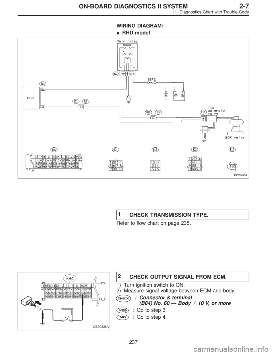
WIRING DIAGRAM:
�RHD model
B2M0454
1
CHECK TRANSMISSION TYPE.
Refer to flow chart on page 235.
OBD0326A
2
CHECK OUTPUT SIGNAL FROM ECM.
1) Turn ignition switch to ON.
2) Measure signal voltage between ECM and body.
: Connector & terminal
(B84) No. 60—Body / 10 V, or more
: Go to step 3.
: Go to step 4.
237
2-7ON-BOARD DIAGNOSTICS II SYSTEM
11. Diagnostics Chart with Trouble Code

 Turn ignition switch to OFF.
2) Disconnect connector from ECM.
3) Measure resistance between ECM harness connector
and body.
: Connector & terminal
(B84) No. 30—Body/700")