Page 1530 of 2248
OBD0676A
6CHECK POWER SUPPLY TO PRESSURE
SOURCES SWITCHING SOLENOID VALVE.
1) Turn ignition switch to ON.
2) Measure voltage between pressure sources switching
solenoid valve harness connector and body.
: Connector & terminal
(B1) No. 2—Body / 10 V, or more
: Confirm good connection at pressure sources
switching solenoid valve connector.
: Repair open circuit of harness between main relay
connector and pressure sources switching sole-
noid valve connector.
324
2-7ON-BOARD DIAGNOSTICS II SYSTEM
11. Diagnostics Chart with Trouble Code
Page 1532 of 2248
OBD0491A
1
CHECK INPUT SIGNAL FOR ECM.
1) Turn ignition switch to ON.
2) Measure voltage between ECM and body.
: Connector & terminal
(B84) No. 49—Body / 4.5V, or more
: Go to next.
: Go to step 2.
: Is there poor contact in ECM connector?
: Repair poor contact in ECM connector.
: Replace ECM with a new one.
OBD0492B
2CHECK HARNESS CONNECTOR BETWEEN
ECM AND TCM.
1) Turn ignition switch to OFF.
2) Disconnect connectors from ECM and TCM.
3) Measure resistance of harness connector between
ECM and TCM.
: Connector & terminal
(B84) No. 49—(B55) No. 16 / 10Ω, or less
: Go to next step.
: Repair open circuit of harness between ECM con-
nector and TCM connector.
326
2-7ON-BOARD DIAGNOSTICS II SYSTEM
11. Diagnostics Chart with Trouble Code
Page 1535 of 2248
1CHECK IF THE VEHICLE IS EQUIPPED WITH
TCS.
: Is the vehicle equipped with TCS?
: Go to step 4.
: Go to step 2.
OBD0497A
2
CHECK OUTPUT SIGNAL FROM ECM.
1) Turn ignition switch to ON.
2) Measure voltage between ECM connector and body.
: Connector & terminal
(B84) No. 34—Body / 2 V, or more
: Repair poor contact in ECM connector.
: Go to step 3.
OBD0499A
3
CHECK HARNESS CONNECTOR.
1) Turn ignition switch to OFF.
2) Remove front passenger side seat.
3) Tear off the floor mat.
4) Disconnect connectors from ECM and TCS C/M.
5) Measure resistance between ECM harness connector
and body.
: Connector & terminal
(B84) No. 34—Body / 10Ω, or less
: Repair short circuit of harness between ECM con-
nector and TCS C/M connector.
: Go to next step.
329
2-7ON-BOARD DIAGNOSTICS II SYSTEM
11. Diagnostics Chart with Trouble Code
Page 1536 of 2248
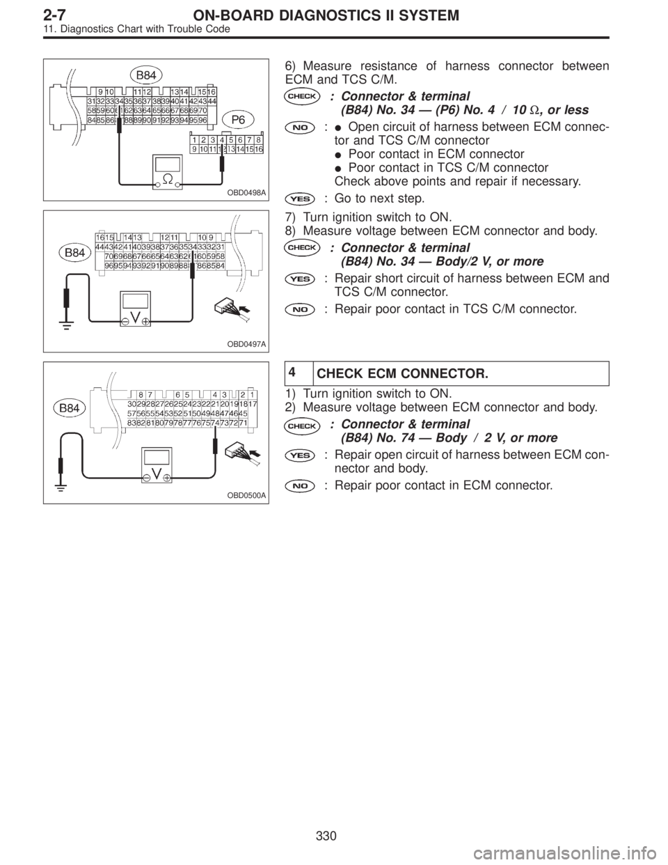
OBD0498A
6) Measure resistance of harness connector between
ECM and TCS C/M.
: Connector & terminal
(B84) No. 34—(P6) No. 4 / 10Ω, or less
:�Open circuit of harness between ECM connec-
tor and TCS C/M connector
�Poor contact in ECM connector
�Poor contact in TCS C/M connector
Check above points and repair if necessary.
: Go to next step.
OBD0497A
7) Turn ignition switch to ON.
8) Measure voltage between ECM connector and body.
: Connector & terminal
(B84) No. 34—Body/2 V, or more
: Repair short circuit of harness between ECM and
TCS C/M connector.
: Repair poor contact in TCS C/M connector.
OBD0500A
4
CHECK ECM CONNECTOR.
1) Turn ignition switch to ON.
2) Measure voltage between ECM connector and body.
: Connector & terminal
(B84) No. 74—Body / 2 V, or more
: Repair open circuit of harness between ECM con-
nector and body.
: Repair poor contact in ECM connector.
330
2-7ON-BOARD DIAGNOSTICS II SYSTEM
11. Diagnostics Chart with Trouble Code
Page 1540 of 2248
OBD0736A
1
CHECK OUTPUT SIGNAL FROM ECM.
1) Turn ignition switch to OFF.
2) Connect test mode connector at the lower portion of
instrument panel (on the driver’s side), to the side of the
center console box.
3) Turn ignition switch to ON.
OBD0674A
4) Measure voltage between ECM and body.
: Connector & terminal
(B84) No. 77—Body/10 V, or more and 1 V
or less at every 2 seconds
: Go to step 6.
: Go to next.
OBD0534A
: Connector & terminal
(B84) No. 88—Body/10 V, or more
: Go to step 5.
: Go to step 2.
2
CHECK POWER SUPPLY FOR RELAYS.
Turn ignition switch to OFF.
: Is the fuse in power supply circuit broken?
: Replace the fuse.
: Go to step 3.
OBD0535
3CHECK MAIN FAN RELAY 1, SUB FAN RELAY
1 AND MAIN FAN RELAY.
1) Remove main fan relay 1. (With A/C models only)
2) Measure resistance between main fan relay 1 termi-
nals.
: Terminal
No. 1—No. 3/97±10Ω
: Go to next step.
: Replace main fan relay 1.
334
2-7ON-BOARD DIAGNOSTICS II SYSTEM
11. Diagnostics Chart with Trouble Code
Page 1542 of 2248
OBD0686A
: Connector & terminal
(F28) No. 1—(B72) No. 5 / 10Ω, or less
: Go to next.
: Repair open circuit of harness between main fan
relay 1 connector and ignition switch connector.
: Is there poor contact in main fan relay 1 or
ignition switch connector?
: Repair main fan relay 1 or ignition switch connec-
tor.
: Go to next.
NOTE:
With A/C models only.
OBD0687A
: Connector & terminal
(B52) No. 4—(B72) No. 2 / 10Ω, or less
: Go to next.
: Repair open circuit of harness between sub fan
relay 1 (with A/C models) or main fan relay (with-
out A/C models) connector and ignition switch
connector.
: Is there poor contact in sub fan relay 1 (with
A/C models) or main fan relay (without A/C
models) or ignition switch connector?
: Repair sub fan relay 1 (with A/C models) or main
fan relay (without A/C models) or ignition switch
connector.
: Replace ECM with a new one.
336
2-7ON-BOARD DIAGNOSTICS II SYSTEM
11. Diagnostics Chart with Trouble Code
Page 1543 of 2248
 Turn ignition switch to OFF.
2) Remove main fan relay 1 and sub fan relay 1. (with A/C
models)
Remove main fan relay. (without A/C models)
3) Disconnect test mod")
OBD0534A
5
CHECK HARNESS CONNECTOR.
1) Turn ignition switch to OFF.
2) Remove main fan relay 1 and sub fan relay 1. (with A/C
models)
Remove main fan relay. (without A/C models)
3) Disconnect test mode connector.
4) Turn ignition switch to ON.
5) Measure voltage between ECM and body.
: Connector & terminal
(B84) No. 88—Body / 10 V, or more
: Repair short circuit of harness and replace ECM.
: Go to next.
: Is there poor contact in ECM connector?
: Repair poor contact in ECM connector.
: Replace ECM.
OBD0674A
6
CHECK MONITOR LINE.
1) Turn ignition switch to OFF.
2) Connect test mode connector.
3) Turn ignition switch to ON.
4) Measure voltage between ECM and body.
: Connector & terminal
(B84) No. 77—Body / 10 V, or more and 1
V, or less at every 2
seconds.
: Repair poor contact in ECM connector.
: Repair open circuit of harness between ECM con-
nector and sub fan relay 1 (with A/C models) or
main fan relay (without A/C models).
337
2-7ON-BOARD DIAGNOSTICS II SYSTEM
11. Diagnostics Chart with Trouble Code
Page 1550 of 2248
WIRING DIAGRAM:
OBD0512
OBD0514A
1.CHECK HARNESS CONNECTOR BETWEEN
TCM AND CCM.
1) Turn ignition switch to OFF.
2) Disconnect connectors from TCM and CCM.
3) Measure resistance of harness connector between
TCM and CCM.
: Connector & terminal
(B56) No. 3—(B94) No. 3 / 10Ω, or less
: Repair open circuit of harness between TCM con-
nector and CCM connector.
: Go to next step.
OBD0515A
4) Measure resistance of harness connector between
TCM and body.
: Connector & terminal
(B56) No. 3—Body / 1 MΩ, or more
: Repair short circuit of harness between TCM con-
nector and CCM connector.
: Go to step 2.
344
2-7ON-BOARD DIAGNOSTICS II SYSTEM
11. Diagnostics Chart with Trouble Code
 Turn ignition switch to ON.
2) Measure voltage between pressure sources switching
solenoid valve harness connector and bod")
 Turn ignition switch to ON.
2) Measure voltage between ECM and body.
: Connector & terminal
(B84) No. 49—Body / 4.5V, or more
: Go to next.
: Go to step 2.")
 Turn ignition switch to ON.
2) Measure volta")
 Turn ignition switch to OFF.
2) Connect test mode connector at the lower portion of
instrument panel (on the driver’s side), to the side of the
center con")
 No. 1—(B72) No. 5 / 10Ω, or less
: Go to next.
: Repair open circuit of harness between main fan
relay 1 connector and ignition switch connector.
: Is there p")
 Turn ignition switch to OFF.
2) Disconnect connectors from TCM and CCM.
3) Measure resistance of harness connector be")