Page 1636 of 1701

SUPPLEMENTALRESTRAINTSYSTEM(SRS)
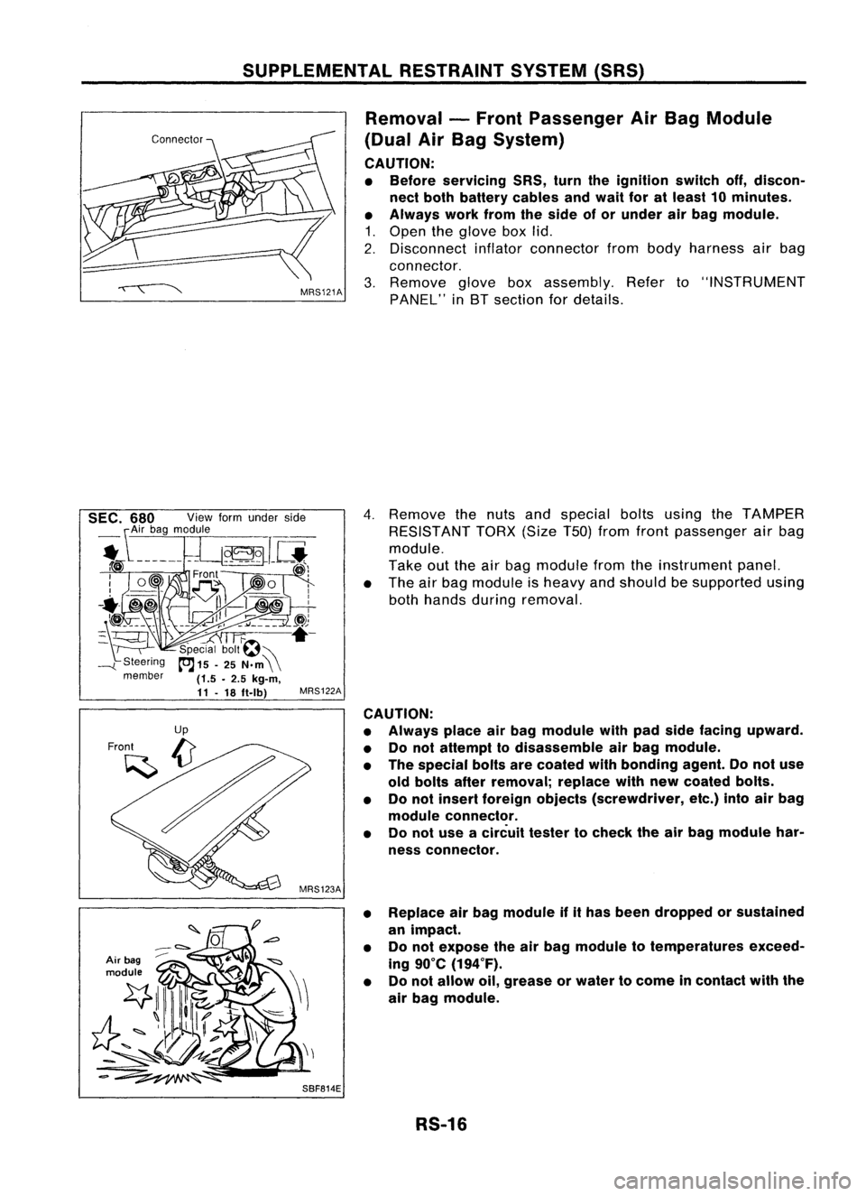
Removal -Front Passenger AirBag Module
(Dual AirBag System)
CAUTION:
• Before servicing SRS,turntheignition switchoff,discon-
nect both battery cablesandwait foratleast 10minutes.
• Always workfromtheside ofor under airbag module.
1. Open theglove boxlid.
2. Disconnect inflatorconnector frombody harness airbag
connector.
3. Remove gloveboxassembly. Referto"INSTRUMENT
PANEL" inBT section fordetails.
Air bag
module
4.
Remove thenuts andspecial boltsusing theTAMPER
RESISTANT TORX(SizeT50jfrom front passenger airbag
module.
Take outtheairbag module fromtheinstrument panel.
• The airbag module isheavy andshould besupported using
both hands during removal.
MRS122A
CAUTION:
• Always placeairbag module withpadside facing upward.
• Donot attempt todisassemble airbag module.
• The special boltsarecoated withbonding agent.Donot use
old bolts afterremoval; replacewithnewcoated bolts.
• Donot insert foreign objects (screwdriver, etc.)intoairbag
module connector.
• Donot use acircuit testertocheck theairbag module har-
ness connector.
• Replace airbag module ifithas been dropped orsustained
an impact.
• Donot expose theairbag module totemperatures exceed-
ing 90°C (194°F).
• Donot allow oil,grease orwater tocome incontact withthe
air bag module.
SBF814E RS-16
Page 1660 of 1701

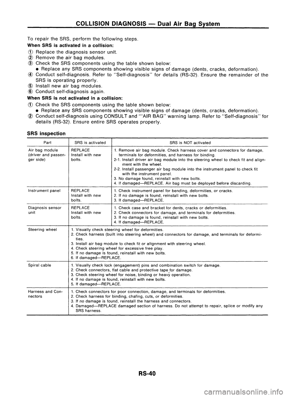
COLLISIONDIAGNOSIS -Dual AirBag System
To repair theSRS, perform thefollowing steps.
When SRSisactivated inacollision:
CD
Replace thediagnosis sensorunit.
@ Remove
theairbag modules.
@
Check theSRS components usingthetable shown below:
• Replace anySRS components showing
visible
signsofdamage (dents,cracks, deformation).
@
Conduct self-diagnosis. Referto"Self-diagnosis" fordetails (RS-32). Ensuretheremainder ofthe
SRS isoperating properly.
Install newairbag modules.
@
Conduct self-diagnosis again.
When SRSisnot activated inacollision:
CD
Check theSRS components usingthetable shown below:
• Replace anySRS components showingvisiblesignsofdamage (dents,cracks, deformation).
@
Conduct self-diagnosis usingCONSULT and"'AIR BAG" warning lamp.Referto"Self-diagnosis" for
details (RS-32). EnsureentireSRSoperates properly.
SRS inspection
Part SRSisactivated
SRSisNOT activated
Air bag module REPLACE
1.Remove airbag module. Checkharness coverandconnectors fordamage,
(driver andpassen-
Installwithnew terminalsfordeformities, andharness forbinding.
ger side) bolts.
2-1.Install driverairbag module intothesteering wheeltocheck fitand align-
ment withthewheel.
2-2. Install passenger airbag module intotheinstrument paneltocheck fit
with theinstrument panel.
3. No damage found,reinstall withnewbolts.
4. Ifdamaged-REPLACE. Airbag must bedeployed beforediscarding.
Instrument panel
REPLACE 1.Check instrument panelforbending, deformities, orcracks.
Install withnew
2.Ifno damage isfound, reinstall withnewbolts.
bolts. 3.Ifdamaged-REPLACE.
Diagnosis sensor REPLACE
1.Check caseandbracket fordents, cracks ordeformities.
unit Installwithnew
2.Check connectors fordamage, andterminals fordeformities.
bolts. 3.Ifno damage isfound, reinstall withnewbolts.
4. Ifdamaged-REPLACE.
Steering wheel
1.Visually checksteering wheelfordeformities.
2. Check harness (builtintosteering wheel)andconnectors fordamage, andterminals fordeformi-
ties.
3. Install airbag module tocheck fitor alignment withsteering wheel.
4. Check steering wheelforexcessive freeplay.
5. Ifno damage isfound, reinstall withnewbolts.
6. Ifdamaged-REPLACE.
Spiral cable
1.Visually checklock(engagement) pinsandcombination switchfordamage.
2. Check connectors, flatcable andprotective tapefordamage.
3. Check steering wheelfornoise, binding orheavy operation.
4. Ifno damage isfound, reinstall withnew bolts.
5. Ifdamaged-REPLACE.
Harness andCon-
1.Check connectors forpoor connection, damage,andterminals fordeformities.
nectors 2.Check harness forbinding, chafing,cuts,ordeformities.
3. Ifno damage isfound, reinstall theharness andconnectors.
4. Damaged-REPLACE damagedsectionofharness. Donot attempt torepair, spliceormodify any
SRS harness.
RS-40
Page 1668 of 1701

PRECAUTIONSANDPREPARATION
Precautions
SUPPLEMENTAL RESTRAINTSYSTEM(SRS)"AIRBAG"
(Dual AirBag System)
The Supplemental RestraintSystem"AirBag" usedalong withaseat belt,helps toreduce therisk or
severity ofinjury tothe driver andfront passenger inafrontal collision. TheSupplemental Restraint
System consists ofair bag modules (locatedinthe center ofthe steering wheelandonthe instrument
panel onthe passenger side),adiagnosis sensorunit,warning lamp,wiring harness andspiral cable.
Information necessarytoservice thesystem safelyisincluded inthe
RSsection
ofthis Service Manual.
WARNING: • Toavoid rendering theSRS inoperative, whichcouldincrease therisk ofpersonal injuryordeath
in the event ofacollision whichwould resultinair bag inflation, allmaintenance mustbeperformed
by an authorized NISSANdealer.
• Improper maintenance, includingincorrectremovalandinstallation ofthe SRS, canlead topersonal
injury caused byunintentional activationofthe system.
• Donot use electrical testequipment onany circuit related tothe SRS unless instructed tointhis
Service Manual. SRSwiring harnesses arecovered withyellow insulation eitherjustbefore the
harness connectors orfor the complete harness,foreasy identification.
SUPPLEMENTAL RESTRAINTSYSTEM(SRS)"AIRBAG"
(Single AirBag System)
The Supplemental RestraintSystem"AirBag" andused along withaseat belt,helps toreduce therisk
or severity ofinjury tothe driver inafrontal collision. TheSupplemental RestraintSystemconsists of
an air bag module (located inthe center ofthe steering wheel),adiagnosis sensorunit,warning lamp,
wiring harness andspiral cable. Information necessarytoservice thesystem safelyisincluded inthe
RS section
ofthis Service Manual.
WARNING: • Toavoid rendering theSRS inoperative, whichcouldincrease therisk ofpersonal injuryordeath
in the event ofacollision whichwould resultinair bag inflation, allmaintenance mustbeperformed
by an authorized NISSANdealer.
• Improper maintenance, includingincorrectremovalandinstallation ofthe SRS, canlead topersonal
injury caused byunintentional activationofthe system.
• Donot use electrical testequipment onany circuit related tothe SRS unless instructed tointhis
Service Manual.
STEERINGSYSTEM
• Before disassembly, thoroughlycleantheoutside ofthe unit.
• Disassembly shouldbedone inaclean workarea. Itis important toprevent theinternal partsfrom
becoming contaminated bydirt orother foreign matter.
• Place disassembled partsinorder, onaparts rack,fore"asier andproper assembly.
• Use nylon cloths orpaper towels toclean theparts; common shopragscanleave lintthat might
interfere withtheir operation.
• Before inspection orreassembly, carefullycleanallparts withageneral purpose, non-flammable
solvent.
• Before assembly, applyacoat ofrecommended ATF*tohydraulic parts.Vaseline maybeapplied to
O-rings andseals. Donot use any grease.
• Replace allgaskets, sealsandO-rings. Avoiddamaging O-rings,sealsandgaskets duringinstalla-
tion. Perform functional testswhenever designated.
*:
Automatic transmission fluid
ST-2