1995 NISSAN ALMERA N15 instrument panel
[x] Cancel search: instrument panelPage 1425 of 1701
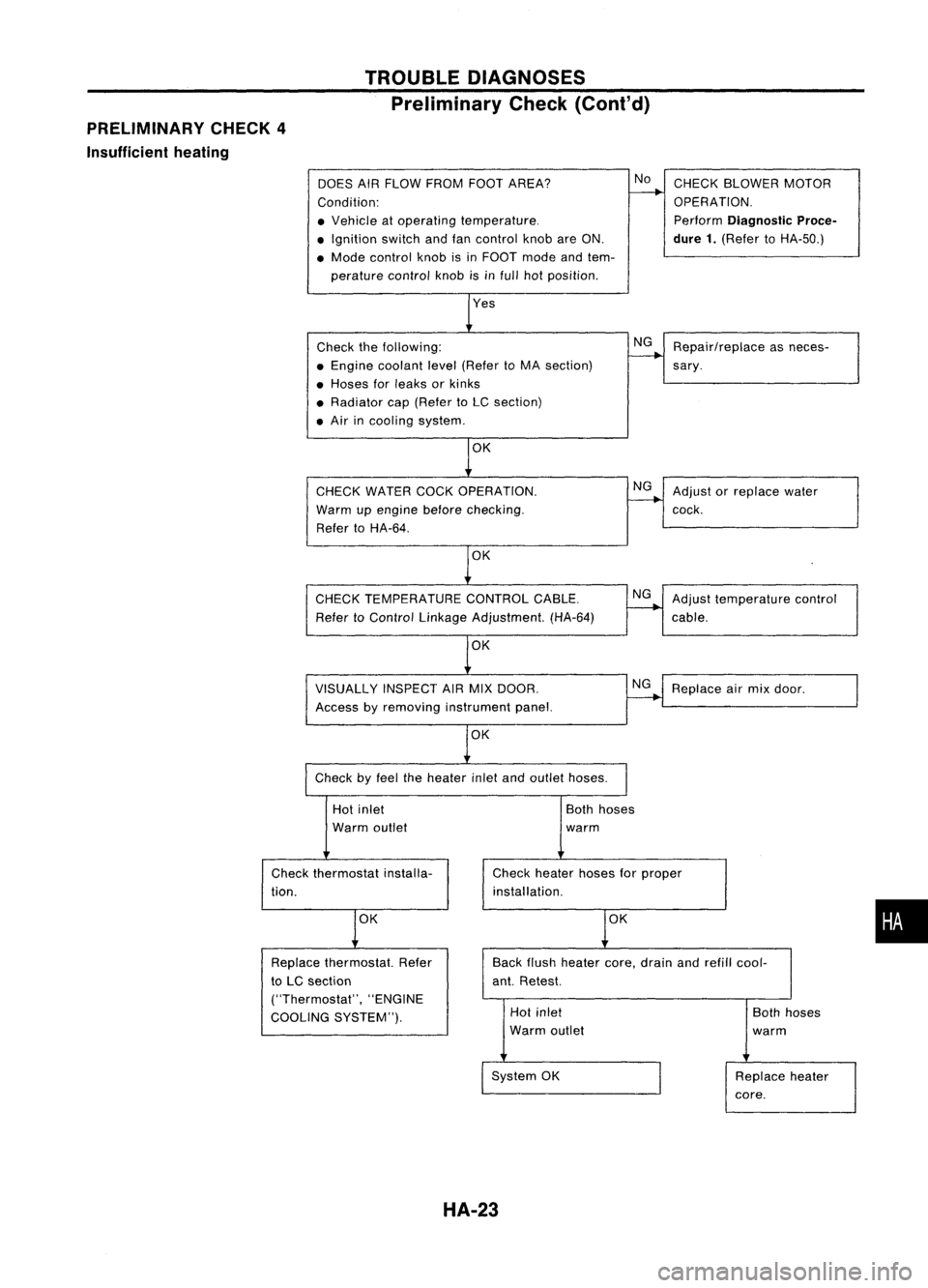
PRELIMINARY CHECK4
Insufficient heating TROUBLE
DIAGNOSES
Preliminary Check(Cont'd)
DOES AIRFLOW FROM FOOTAREA?
Condition:
• Vehicle atoperating temperature .
• Ignition switchandfancontrol knobareON.
• Mode control knobisin FOOT modeandtem-
perature controlknobisinfull hotposition.
Check thefollowing:
• Engine coolant level(Refer toMA section)
• Hoses forleaks orkinks
• Radiator cap(Refer toLC section)
• Air incooling system.
CHECK WATER COCKOPERATION.
Warm upengine before
checking.
Refer toHA-64.
OK
CHECK TEMPERATURE CONTROLCABLE.
Refer toControl Linkage Adjustment. (HA-64)
VISUALLY INSPECTAIRMIX DOOR.
Access byremoving instrument panel.
OK
Check byfeel theheater inletandoutlet hoses.
No
NG
NG
NG
NG
CHECK
BLOWER MOTOR
OPERATION.
Perform
Diagnostic Proce-
dure 1.
(Refer toHA-50.)
Repair/replace asneces-
sary .
Adjust orreplace water
cock.
Adjust temperature control
cable.
Replace airmix door.
Hot inlet
Warm outlet
Check thermostat installa-
tion.
OK
Both
hoses
warm
Check heater hosesforproper
installation.
OK
•
Back
flush heater core,drain andrefill cool-
ant. Retest.
Replace
thermostat. Refer
to LC section
("Thermostat", "ENGINE
COOLING SYSTEM"). Hot
inlet
Warm outlet
System OK
HA-23
Both
hoses
warm
Replace heater
core.
Page 1485 of 1701
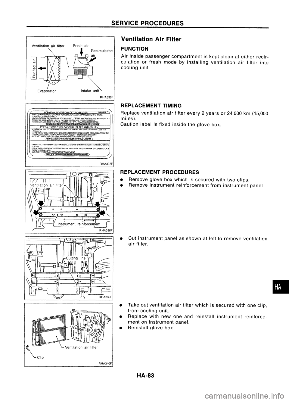
Ventilationairfilter
Evaporator SERVICE
PROCEDURES
Ventilation AirFilter
FUNCTION
Air inside passenger compartment iskept clean ateither recir-
culation orfresh mode byinstalling ventilation airfilter into
cooling unit.
RHA336F REPLACEMENT TIMING
Replace ventilation airfilter every 2years or24,000 km(15,000
miles).
C-aution labelisfixed inside theglove box.
REPLACEMENT PROCEDURES
• Remove gloveboxwhich issecured withtwoclips.
• Remove instrument reinforcement frominstrument panel.
• Cut instrument panelasshown atleft toremove ventilation
air filter.
• Take outventilation airfilter which issecured withoneclip,
from cooling unit.
• Replace withnewoneand reinstall instrument reinforce-
ment oninstrument panel.
• Reinstall glovebox.
•
RHA340F HA-83
Page 1489 of 1701
PRECAUTIONSANDPREPARATION
Supplemental RestraintSystem(SRS)"AIR
BAG" (DualAirBag System)
The Supplemental RestraintSystem"AirBag", usedalong withaseat belt,helps toreduce therisk or•
severity ofinjury tothe driver andfront passenger inafrontal collision. TheSupplemental Restraint
i
System consists ofair bag modules (locatedinthe center ofthe steering wheelandonthe instrument
panel onthe passenger side).adiagnosis sensorunit,warning lamp,wiring harness andspiral cable.
Information necessarytoservice thesystem safelyisincluded inthe
RSsection
ofthis Service Manual.
WARNING:
• Toavoid rendering theSRS inoperative, whichcouldincrease therisk ofpersonal injuryordeath
in the event ofacollision whichwould resultinair bag inflation, allmaintenance mustbeperformed
by an authorized NISSANdealer.
• Improper maintenance, includingincorrectremovalandinstallation ofthe SRS, canlead topersonal
injury caused byunintentional activationofthe system.
• Donot use electrical testequipment onany circuit related tothe SRS unless instructed tointhis
Service Manual. SRSwiring harnesses arecovered withyellow insulation eitherjustbefore the
harness connectors orfor the complete harness,foreasy identification.
Supplemental RestraintSystem(SRS)"AIR
BAG" (Single AirBag System)
The Supplemental RestraintSystem"AirBag", usedalong withaseat belt,helps toreduce therisk or
severity ofinjury tothe driver inafrontal collision. TheSupplemental RestraintSystemconsists ofan
air bag module (located inthe center ofthe steering wheel),adiagnosis sensorunit,warning lamp,
wiring harness andspiral cable. Information necessarytoservice thesystem safelyisincluded inthe
RS section
ofthis Service Manual.
WARNING:
• Toavoid rendering theSRS inoperative, whichcouldincrease therisk ofpersonal injuryordeath
in the event ofacollision whichwould resultinair bag inflation, allmaintenance mustbeperformed
by an authorized NISSANdealer.
• Improper maintenance, includingincorrectremovalandinstallation ofthe SRS, canlead topersonal
injury caused byunintentional activationofthe system.
• Donot use electrical testequipment onany circuit related tothe SRS.
MA-3
Page 1491 of 1701
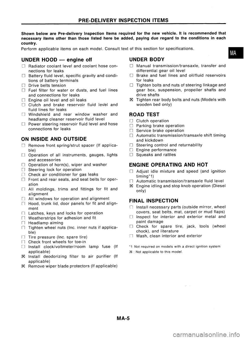
PRE-DELIVERYINSPECTIONITEMS
Shown belowarePre-delivery InspectionItemsrequired forthe new vehicle. Itis recommended that
necessary itemsotherthanthose listedherebeadded, payingdueregard tothe conditions ineach
country.
Perform applicable itemsoneach model. Consult textofthis section forspecifications .
UNDER HOOD-engine off
o
Radiator coolantlevelandcoolant hosecon-
nections forleaks
o
Battery fluidlevel, specific gravityandcondi-
tions ofbattery terminals
o
Drive beltstension
D
Fuel filter forwater ordusts, andfuel lines
and connections forleaks
[] Engine oillevel andoilleaks
D
Clutch andbrake reservoir fluidlevel and
fluid lines forleaks
o
Windshield andrear window washerand
headlamp cleanerreservoir fluidlevel
D
Power steering reservoir fluidlevel andhose
connections forleaks
ON INSIDE ANDOUTSIDE
D
Remove frontspring/strut spacer(Ifapplica-
ble)
D
Operation ofall instruments, gauges,lights
and accessories
o
Operation ofhorn(s), wiperandwasher
[] Steering lockforoperation
[] Check airconditioner forgas leaks
o
Front andrear seats, andseat belts foroper-
ation
n
All moldings, trimsandfittings forfitand
alignment
[J
Allwindows foroperation andalignment
n
Hood, trunklid,door panels forfitand align-
ment
[1
Latches, keysandlocks foroperation
rl
Weatherstrips foradhesion andfit
[l
Headlamp aiming
I~ Tighten wheelnuts(Inc. inner nutsifapplica-
ble)
IJ Tire pressure (Inc.spare tire)
Il
Check frontwheels fortoe-in
IJ Install clock/voltmeter/room lampfuse(If
applicable)
~ Install deodorizing filtertoair purifier (If
applicable)
~ Remove wiperbladeprotectors (Ifapplicable)
UNDER
BODY
o
Manual transmission/transaxle, transferand
differential gearoillevel
D
Brake andfuel lines andoil/fluid reservoirs
for leaks
D
Tighten boltsandnuts ofsteering linkageand
gear box,suspension, propellershaftsand
drive shafts
~ Tighten rearbody boltsandnuts (Models with
wooden bedonly)
ROAD TEST
D
Clutch operation
D
Parking brakeoperation
[J
Service brakeoperation
D
Automatic transmission/transaxle shifttiming
and kickdown
[] Steering controlandreturnability
o
Engine performance
D
Squeaks andrattles
ENGINE OPERATING ANDHOT
D
Adjust idlemixture andspeed (andignition
timing*1)
n
Automatic transmission/transaxle fluidlevel
~ Engine idlingandstop knob operation (Diesel
only)
FINAL INSPECTION
n
Install necessary parts(outside mirror,wheel
covers, seatbelts, mat,carpet ormud flaps)
[1
Inspect forinterior andexterior metaland
paint damage
[] Check forspare tire,jack, tools (wheel
chock), andliterature
n
Wash, cleaninterior andexterior
"1: Not required onmodels withadirect ignition system
~ :Not appiicable tothis model.
•
MA-5
Page 1622 of 1701
PRECAUTION
Supplemental RestraintSystem(SRS)"AIR
BAG" (DualAirBag System)
The Supplemental RestraintSystem"AirBag", usedalong withaseat belt, helps toreduce therisk or
severity ofinjury tothe driver andfront passenger inafrontal collision. TheSupplemental Restraint
System consists ofair bag modules (locatedinthe center ofthe steering wheelandonthe instrument
panel onthe passenger side),adiagnosis sensorunit,warning lamp,wiring harness andspiral cable.
WARNING:
• Toavoid rendering theSRS inoperative, whichcouldincrease therisk ofpersonal injuryordeath
in the event ofacollision whichwould resultinair bag inflation, allmaintenance mustbeperformed
by an authorized NISSANdealer.
• Improper maintenance, includingincorrectremovalandinstallation ofthe SRS, canlead topersonal
injury caused byunintentional activationofthe system.
• Donot use electrical testequipment onany circuit related tothe SRS unless instructed tointhis
Service Manual. SRSwiring harnesses arecovered withyellow insulation eitherjustbefore the
harness connectors orfor the complete harness,foreasy identification.
Supplemental RestraintSystem(SRS)"AIR
BAG" (Single AirBag System)
The Supplemental RestraintSystem"AirBag", usedalong withaseat belt, helps toreduce therisk or
severity ofinjury tothe driver inafrontal collision. TheSupplemental RestraintSystemconsists ofan
air bag module (located inthe center ofthe steering wheel),adiagnosis sensorunit,warning lamp,
wiring harness andspiral cable.
WARNING:
• Toavoid rendering theSRS inoperative, whichcouldincrease therisk ofpersonal injuryordeath
in the event ofacollision whichwould resultinair bag inflation, allmaintenance mustbeperformed
by an authorized NISSANdealer.
• Improper maintenance, includingincorrectremovalandinstallation ofthe SRS, canlead topersonal
injury caused byunintentional activationofthe system.
• Donot use electrical testequipment onany circuit related tothe SRS unless instructed tointhis
Service Manual.
RS-2
Page 1628 of 1701
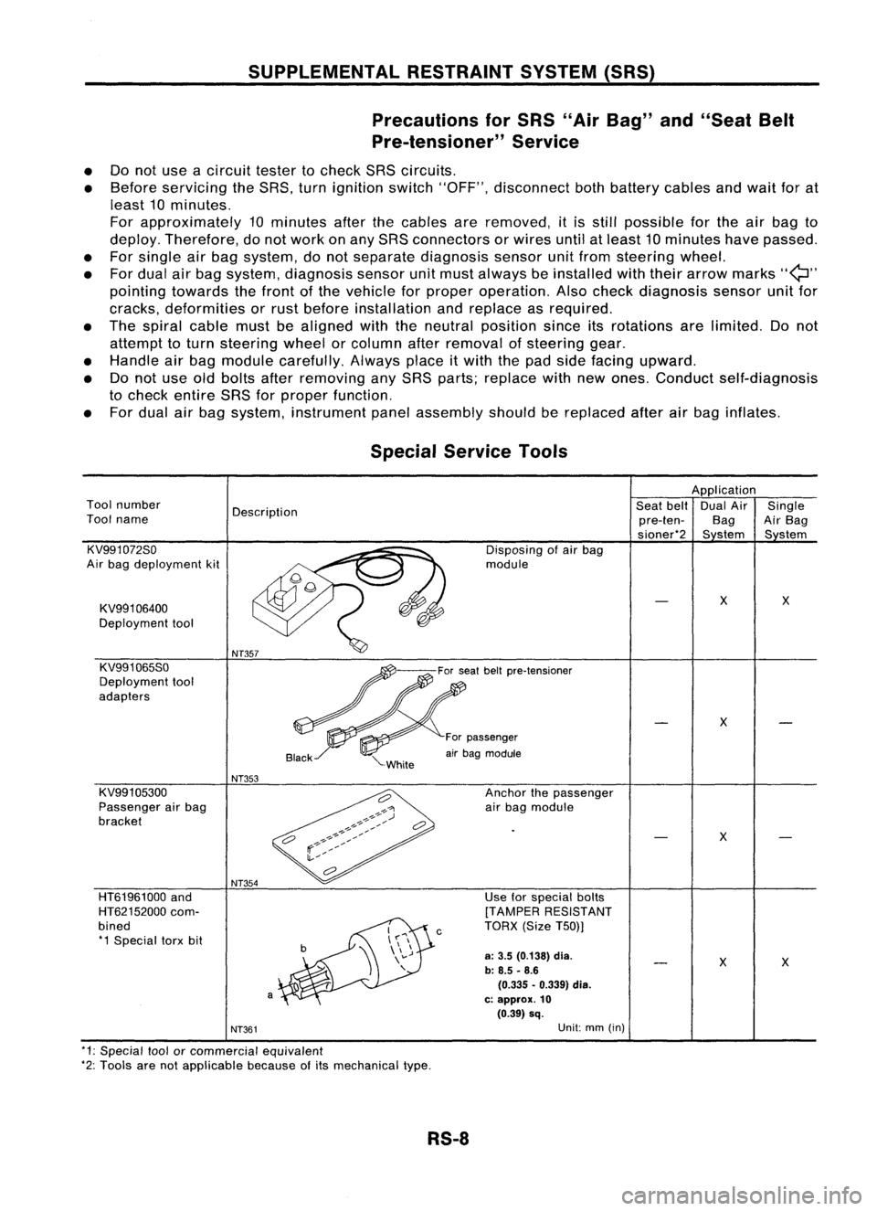
SUPPLEMENTALRESTRAINTSYSTEM(SRS)
Precautions forSRS "AirBag" and"Seat Belt
Pre-tensioner" Service
• Donot use acircuit testertocheck SRScircuits.
• Before servicing theSRS. turnignition switch"OFF", disconnect bothbattery cablesandwait forat
least 10minutes.
For approximately 10minutes afterthecables areremoved, itis still possible forthe airbag to
deploy. Therefore, donot work onany SRS connectors orwires untilatleast 10minutes havepassed.
• For single airbag system, donot separate diagnosis sensorunitfrom steering wheel.
• For dual airbag system. diagnosis sensorunitmust always beinstalled withtheir arrow marks
"Q"
pointing towards thefront ofthe vehicle forproper operation. Alsocheck diagnosis sensorunitfor
cracks. deformities orrust before installation andreplace asrequired.
• The spiral cablemustbealigned withtheneutral position sinceitsrotations arelimited. Donot
attempt toturn steering wheelorcolumn afterremoval ofsteering gear.
• Handle airbag module carefully. Alwaysplaceitwith thepad side facing upward.
• Donot use oldbolts afterremoving anySRS parts; replace withnewones. Conduct self-diagnosis
to check entire SRSforproper function.
• For dual airbag system, instrument panelassembly shouldbereplaced afterairbag inflates.
X
X
Use
forspecial bolts
[TAMPER RESISTANT
TORX (SizeT50))
a:
3.5 (0.138)
dia.
b: 8.5 -8.6
(0.335 •0.339) dia.
c: approx.
10
(0.39) sq.
c
NT354
a
HT61961000
and
HT62152000 com-
bined *1 Special torxbit
Special
Service Tools
Application
Tool number
Description Seat
belt DualAir Single
Tool name
pre-ten-BagAirBag
sioner*2 Sstem Sstem
KV991072So Disposingofair bag
Air bag deployment kit module
KV991 06400
X
X
Deployment tool
KV991065So
Deployment tool
adapters
X
For passenger
air bag module
NT353
KV991 05300 Anchorthepassenger
Passenger airbag
airbag module
bracket
X
NT361
Unit:
mm(in)
*1: Special toolorcommercial equivalent
*2: Tools arenotapplicable becauseofits mechanical type.
RS-8
Page 1631 of 1701
SUPPLEMENTALRESTRAINTSYSTEM(SRS)
Visually checkSRScomponents
Diagnosis sensorunit
Check diagnosis sensorunitand bracket fordents, cracks
or deformities.
Check connectors fordamage, andterminals fordeformi-
ties.
Air bag module andsteering wheel
Remove airbag module fromsteering wheelorinstrument
panel. Check harness coverandconnectors fordamage,
terminals fordeformities, andharness forbinding.
Install driversideairbag module tosteering wheeltocheck
fit or alignment withthewheel.
Check steering wheelforexcessive freeplay.
For dual airbag system, installpassenger sideairbag
module toinstrument paneltocheck fitor alignment withthe
instrument panel.
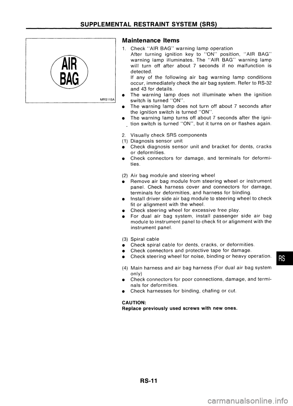
Maintenance
Items
1. Check "AIRBAG" warning lampoperation
After turning ignition keyto"ON" position, "AIRBAG"
warning lampilluminates. The"AIR BAG" warning lamp
will turn offafter about 7seconds ifno malfunction is
detected. If any ofthe following airbag warning lampconditions
occur, immediately checktheairbag system. RefertoRS-32
and 43for details.
The warning lampdoesnotilluminate whentheignition
switch isturned "ON".
The warning lampdoesnotturn offabout 7seconds after
the ignition switchisturned "ON".
The warning lampturns offabout 7seconds aftertheigni-
tion switch isturned "ON",butitturns onorflashes again.
•
MRS115A
•
•
2. (1)
•
•
(2)
•
•
•
•
(3) Spiral cable
• Check spiralcablefordents, cracks, ordeformities.
• Check connectors andprotective tapefordamage.
• Check steering wheelfornoise, binding orheavy operation. •
(4) Main harness andairbag harness (Fordual airbag system
only)
• Check connectors forpoor connections, damage,andtermi-
nals fordeformities.
• Check harnesses forbinding, chafingorcut.
CAUTION: Replace previously usedscrews withnewones.
RS-11
Page 1632 of 1701
SUPPLEMENTALRESTRAINTSYSTEM(SRS)
Removal andInstallation -Diagnosis Sensor
Unit
CAUTION:
• Before servicing SRS,turntheignition switchoff,disconnect bothbattery cablesandwait foratleast
10 minutes.
• The special boltsarecoated withbonding agentwhiletheother boltisfor ground. Donot use old
bolts afterremoval; replacewithnewones.
• For single airbag system, donot separate diagnosis sensorunitfrom steering wheel.
• For dual airbag system, checkdiagnosis sensorunitforproper installation.
• Check diagnosis sensorunittoensure theyarefree ofdeformities, dents,cracks orrust. Ifthey show
any visible signsofdamage, replacethemwithnewones.
• Check diagnosis sensorunitbrackets toensure theyarefree ofdeformities orrust.
• Always workfromtheside ofair bag module.
• Replace diagnosis sensorunitifithas been dropped orsustained animpact.
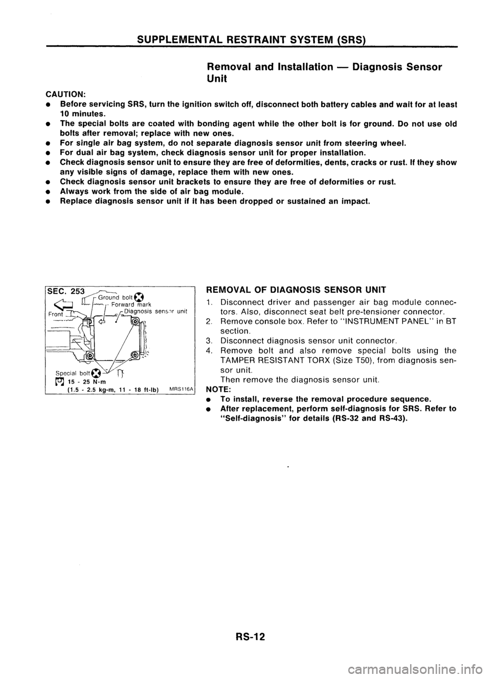
SEC. 253~
IT
r
Grou~? bolt~
G ~~ ~
Forward mark
Fr?nt
_--I
d--!
Dia~no:iS senSlrunit
!
Special bOIt~ -
t"'J
15-25 N.m
(1.5 •2.5 kg-m,
11-
18 ft-Ib)
MRS116A REMOVAL
OFDIAGNOSIS SENSORUNIT
1. Disconnect driverandpassenger airbag module connec-
tors. Also, disconnect seatbeltpre-tensioner connector.
2. Remove consolebox.Refer to"INSTRUMENT PANEL"in8T
section.
3. Disconnect diagnosissensorunitconnector.
4. Remove boltandalso remove specialboltsusing the
TAMPER RESISTANT TORX(SizeT50),fromdiagnosis sen-
sor unit.
Then remove thediagnosis sensorunit.
NOTE:
• Toinstall, reverse theremoval procedure sequence.
• After replacement, performself-diagnosis forSRS. Refer to
"Self-diagnosis" fordetails (RS-32andRS-43).
RS-12