1995 NISSAN ALMERA N15 instrument panel
[x] Cancel search: instrument panelPage 742 of 1701
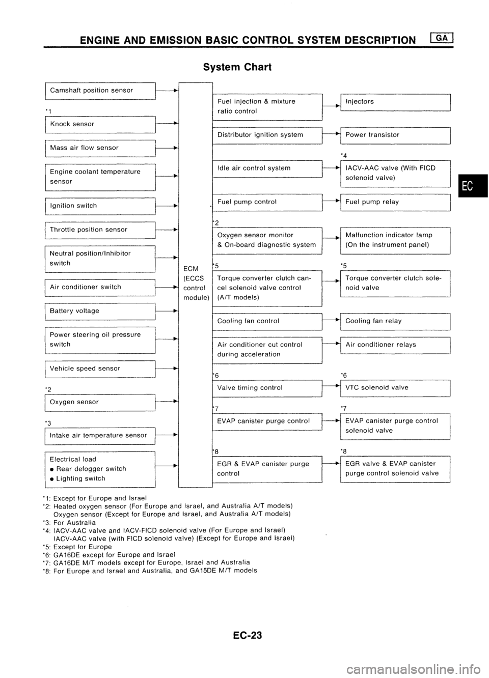
ENGINEANDEMISSION BASICCONTROL SYSTEMDESCRIPTION
System Chart
I
Camshaft positionsensor
'1
Fuel
injection
&
mixture
ratio control Injectors
Knock sensor
Distributorignitionsystem Powertransistor
Mass airflow sensor
Engine coolant temperature
sensor
Ignition switch Idle
aircontrol system
Fuel pump control
*4
IACV-AAC valve(WithFICD
solenoid valve)
Fuel pump relay
•
'5
Throttle
positionsensor
Neutral positionllnhibitor
switch
Air conditioner switch ECM
(ECCS
control
module)
2
Oxygen sensormonitor
&
On-board diagnostic system
5
Torque converter clutchcan-
cel solenoid valvecontrol
(A/T models) Malfunction
indicatorlamp
(On theinstrument panel)
Torque converter clutchsole-
noid valve
VTC solenoid valve
*6
Air
conditioner relays
Cooling
fanrelay
EVAP canister purgecontrol
solenoid valve
Cooling
fancontrol
Air conditioner cutcontrol
during acceleration
Valve timing control
EVAP canister purgecontrol
7
6
Power
steering oilpressure
switch Battery
voltage
Intake airtemperature sensor
*3
I
Vehicle speedsensor
*2
I
Oxygen sensor
8
'8
Electrical load
• Rear defogger switch
• Lighting switch EGR
&
EVAP canister purge
control EGR
valve
&
EVAP canister
purge control solenoid valve
*1: Except forEurope andIsrael
*2: Heated oxygen sensor(ForEurope andIsrael, andAustralia A/Tmodels)
Oxygen sensor(Except forEurope andIsrael, andAustralia A/Tmodels)
*3: For Australia
*4: IACV-AAC valveandIACV-FICD solenoidvalve(ForEurope andIsrael)
IACV-AAC valve(withFICDsolenoid valve)(Except forEurope andIsrael)
'5: Except forEurope
*6: GA16DE exceptforEurope andIsrael
*7: GA16DE MITmodels exceptforEurope, IsraelandAustralia
*8: For Europe andIsrael andAustralia, andGA15DE MITmodels
EC-23
Page 759 of 1701
o
1:<
MONITOR
1<
NO FAIL
0
BASIC
SERVICE PROCEDURE
@KJ
Idle Speedllgnition Timing/IdleMixtureRatio
Adjustment (Cont'd)
@
CMPS.RPM (REF)
MIR
F/C
MNT 2000rpm
RICH
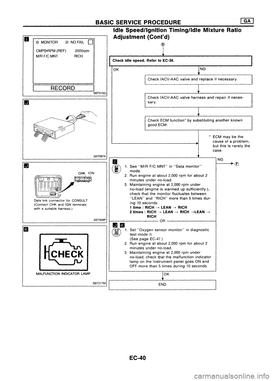
Checkidlespeed. Refer10EC-36.
OK NG
Check IACV-AAC valveandreplace ifnecessary.
__ R_E_C_O_R_D __
I
SEF515Q
CheckIACV-AAC valveharness andrepair ifneces-
sary.
Check ECMfunction- bysubstituting anotherknown
good ECM.
-ECM maybethe
cause ofaproblem,
but this israrely the
case.
SEF987K
(g~~~:: _
mJ
~~r
l~~~~V
-~
Data linkconnector forCONSULT
(Connect CHKandIGN terminals
with asuitable harness.)
SEF909P
MALFUNCTION INDICATORLAMP
SEF217M
o
(ij\E
1.See "MIA
F/C
MNT" in"Data monitor"
~ mode.
2. Run engine atabout 2,000rpmforabout 2
minutes underno-load.
3. Maintaining engineat2,000 rpmunder
no-load (engine iswarmed upsufficiently.),
check thatthemonitor fluctuates between
"LEAN" and"RICH" morethan5times dur-
ing 10seconds.
1 lime: RICH->LEAN ->RICH
2 limes: RICH->LEAN
->
RICH ->LEAN
->
RICH OR
Set "Oxygen sensormonitor" indiagnostic
test mode II.
(See page EC-47.)
2. Run engine atabout 2,000rpmforabout 2
minutes underno-load.
3. Maintaining engineat2,000 rpmunder
no-load, checkthatthemalfunction indicator
lamp onthe instrument panelgoesONand
OFF more than5times during 10seconds.
OK
END
EC-40 NG
Page 761 of 1701
@@
'1: Heated oxygen sensor(ForEurope
and Israel, andAustralia AITmod-
els) Oxygen sensor(Except forEurope
and Israel, andAustralia AITmod-
els)
Ii
1
Race engine twoorthree times under no-load, thenrunengine atidle
speed.
1
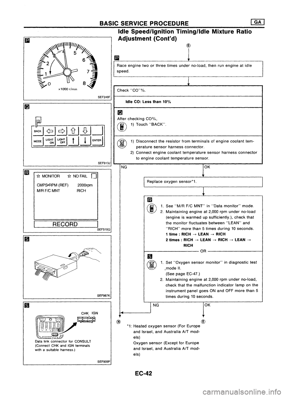
Check "CO"%.
Idle CO:Less than10%
[!J
After checking COOJo,
00
1)
Touch "BACK".
@
1)
Disconnect theresistor fromterminals ofengine coolant tem-
perature sensorh.arness connector.
2) Connect enginecoolant temperature sensorharness connector
to engine coolant temperature sensor.
NG OK
Replace oxygensensor'1.
m
00
1.
See
"M/R
FIC
MNT" in"Data monitor" mode.
2. Maintaining engineat2,000 rpmunder no-load
(engine iswarmed upsufficiently.), checkthat
the monitor fluctuates between"LEAN"and
"RICH" morethan5times during 10seconds.
1 time :RICH
->
LEAN
->
RICH
2 times: RICH
->
LEAN
-+
RICH
->
LEAN
->
RICH
OR
Ii)
@
1.
Set "Oxygen sensormonitor" indiagnostic test
.mode II.
(See page EC-47.)
2. Maintaining
engineat2,000 rpmunder no-load,
check thatthemalfunction indicatorlamponthe
instrument panelgoesONand OFF more than5
times during 10seconds.
I
NG OK
SEF913J
2000rpm
RICH
1;:(
NO FAIL
0
SEF248F
CMPS.RPM (REF)
MIR
FIC
MNT
1;:(
MONITOR
BASIC
SERVICE PROCEDURE ~
Idle Speed/Ignition TiminglldleMixtureRatio
Adjustment (Cont'd)
~\\~\\\\""1"'1///1.
@
#'
7 5~
~ ~
{2{ 6~
?1 7-=1
:;::. .;f
~o 84
xl000 rlmin
SEF987K
(gJ~
~~~~N
l~~i~V-=~
-~
Data linkconnector forCONSULT
(Connect CHKandIGNterminals
with asuitable harness.)
__
R_E_C_O_R_D __
I
SEF515Q
SEF909P EC-42
Page 765 of 1701
ON-BOARDDIAGNOSTIC SYSTEMDESCRIPTION @KJ
Malfunction Indicatorlamp(Mil)(Cont'd)
DIAGNOSTIC TESTMODE I-BULB CHECK
In this mode, theMALFUNCTION INDICATORLAMPonthe instrument panelshould stayON.Ifitremains
OFF, check thebulb. Refer toEL section ("WARNING LAMPSANDCHIME") orsee EC-223.
DIAGNOSTIC TESTMODE I-MALFUNCTION WARNING
MALFUNCTION INDICATORLAMP
ON
OFF Condition
Engine coolant temperature sensorcircuitmalfunction oroverheating isdetected, or
the ECM's CPUismalfunctioning.
No malfunction.
• These Diagnostic TroubleCodeNumbers areclarified inDiagnostic TestMode II(SELF-DIAGNOS-
TIC RESULTS).
DIAGNOSTIC TESTMODE II-SELF-DIAGNOSTIC RESULTS
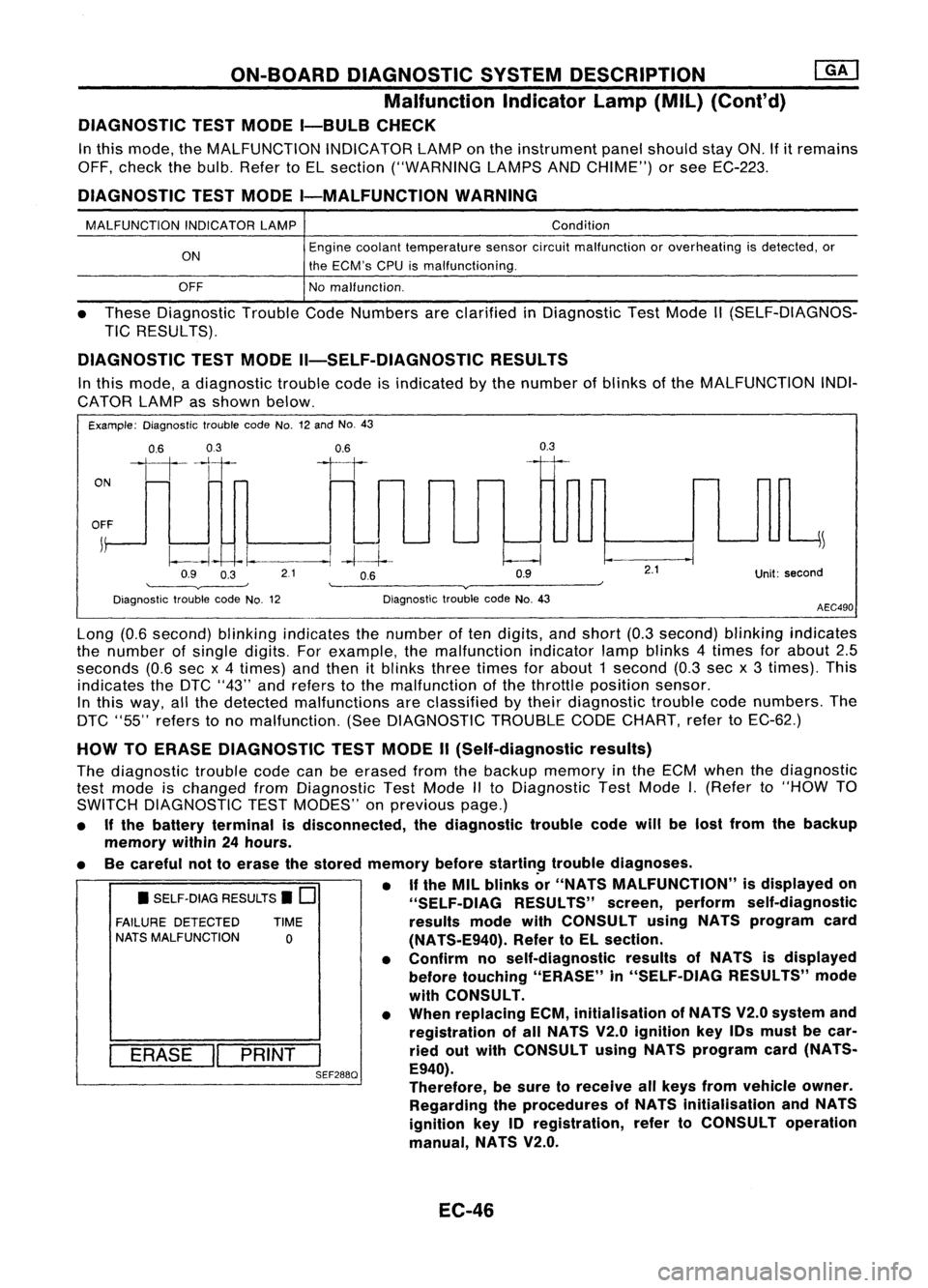
In this mode, adiagnostic troublecodeisindicated bythe number ofblinks ofthe MALFUNCTION INDI-
CATOR LAMPasshown below.
Example: Diagnostic troublecodeNo.12and No.43
ON
0.6
03
111-'1
0.6
II
0.3
OFF
j
~
~~ -I.
--.1
-4--1--
Q9 O~ 21 OB Q9
'--------v----' '--------v------~
Diagnostic troublecodeNo.12 DiagnostictroublecodeNo.43
2.1
Unit:second
AEC490
• SELF-DIAG RESULTS.
0
FAILURE DETECTED TIME
NATS MALFUNCTION
0
I
ERASE
II
PRINT
I
SEF288Q
Long
(0.6second) blinkingindicates thenumber often digits, andshort (0.3second) blinkingindicates
the number ofsingle digits. Forexample, themalfunction indicatorlampblinks 4times forabout 2.5
seconds (0.6secx4 times) andthen itblinks threetimes forabout 1second (0.3secx3 times). This
indicates theDTC "43" andrefers tothe malfunction ofthe throttle position sensor.
In this way, allthe detected malfunctions areclassified bytheir diagnostic troublecodenumbers. The
DTC "55" refers tono malfunction. (SeeDIAGNOSTIC TROUBLECODECHART, refertoEC-62.)
HOW TOERASE DIAGNOSTIC TESTMODE II(Self-diagnostic results)
The diagnostic troublecodecanbeerased fromthebackup memory inthe ECM when thediagnostic
test mode ischanged fromDiagnostic TestMode IIto Diagnostic TestMode
I.
(Refer to"HOW TO
SWITCH DIAGNOSTIC TESTMODES" onprevious page.)
• Ifthe battery terminal isdisconnected, thediagnostic troublecodewillbelost from thebackup
memory within24hours.
• Becareful nottoerase thestored memory before
startin~
troublediagnoses.
• If
the MIL blinks or"NATS MALFUNCTION" isdisplayed on
"SELF-OIAG RESULTS"screen,perform self-diagnostic
results modewithCONSULT usingNATS program card
(NATS-E940). RefertoEL section.
• Confirm noself-diagnostic resultsofNATS isdisplayed
before touching "ERASE" in"SELF-DIAG RESULTS"mode
with CONSULT.
• When replacing ECM,initialisation ofNATS V2.0system and
registration ofall NATS V2.0ignition key10smust becar-
ried outwith CONSULT usingNATS program card(NATS-
E940).
Therefore, besure toreceive allkeys from vehicle owner.
Regarding theprocedures ofNATS initialisation andNATS
ignition key10registration, refertoCONSULT operation
manual, NATS V2.0.
EC-46
Page 783 of 1701
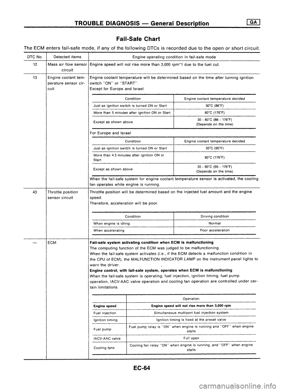
TROUBLEDIAGNOSIS -General Description
Fail-Safe Chart
The ECM enters fail-safe mode,ifany ofthe following DTCsisrecorded duetothe open orshort circuit.
DTC No. Detected
items
Engineoperating conditioninfail-safe mode
12 Massairflow sensor
Enginespeedwillnotrise more than3,000 rpm*1 duetothe fuel cut.
circuit
13 Engine
coolant tem-
Engine coolant temperature willbedetermined basedonthe time after turning ignition
perature sensorcir-switch "ON"or"START".
cuit ExceptforEurope andIsrael
Condition Enginecoolant temperature decided
Just asignition switchisturned ONorStart 30'C(B6'F)
More than5minutes afterignition ONorStart BO'G
(176'F)
Except asshown above 30
-BO'C (B6-176'F)
(Depends onthe time)
For Europe andIsrael
Condition Enginecoolant temperature decided
Just asignition switchisturned ONorStart 35'C
(95'F)
More than4.5minutes afterignition ONor
BO'G(176'F)
Start
Except asshown above 35
-BO'C (95-176'F)
(Depends onthe time)
When thefail-safe systemforengine coolant temperature sensorisactivated, thecooling
fan operates whileengine isrunning.
43 Throttle position Throttle
position willbedetermined basedonthe injected fuelamount andtheengine
sensor circuit speed.
Therefore, acceleration willbepoor.
Condition Driving
condition
When engine isidling Normal
When accelerating Poor
acceleration
-
ECM
Fail-safe
systemactivating conditionwhenECMismalfunctioning
The computing functionofthe ECM wasjudged tobe malfunctioning.
When thefail-safe systemactivates (i.e.,ifthe ECM detects amalfunction conditionin
the CPU ofECM), theMALFUNCTION INDICATORLAMPonthe instrument panellightsto
warn thedriver.
Engine control, withfail-safe system,operates whenECMismalfunctioning
When thefail-safe systemisoperating, fuelinjection, ignitiontiming,fuelpump
operation, IACV-AACvalveoperation andcooling fanoperation arecontrolled undercer-
tain limitations.
Operation
Engine speed Engine
speed
will
notrise more than3,000 rpm
Fuel injection Simultaneous
multipartfuelinjection system
Ignition timing Ignition
timingisfixed atthe preset valve
Fuel pump Fuel
pump' relayis"ON" when engine isrunning and"OFF" whenengine
stalls
IACV-AAG valve Full
open
Cooling fans Cooling
fanrelay "ON" whenengine isrunning, and"OFF" whenengine
stalls
EC-64
Page 910 of 1701
2:
1
:>
Q)
Ol
~
0
>
::;
c.
::;
0
,,"--
0
-
Rich- Idealratio _
Lean
Mixlure ratio
SEF288D
•
Zirconia
tube SEF406H
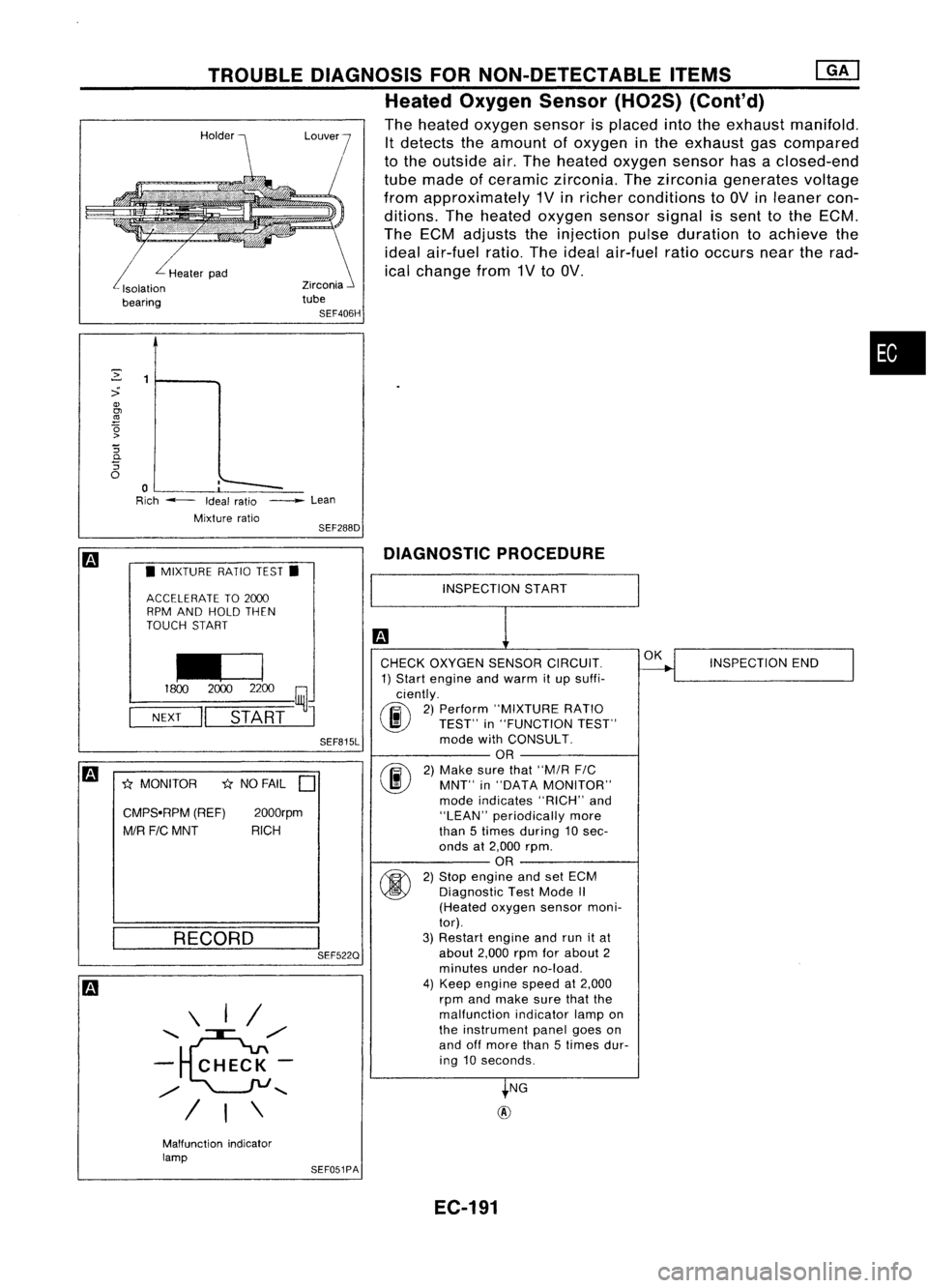
TROUBLE
DIAGNOSIS FORNON-DETECTABLE ITEMS
Heated Oxygen Sensor(H02S)(Cont'd)
The heated oxygen sensorisplaced intotheexhaust manifold.
It detects theamount ofoxygen inthe exhaust gascompared
to the outside air.The heated oxygen sensorhasaclosed-end
tube made ofceramic zirconia. Thezirconia generates voltage
from approximately 1Vinricher conditions to
av
inleaner con-
ditions. Theheated oxygen sensorsignalissent tothe ECM.
The ECM adjusts theinjection pulseduration toachieve the
ideal air-fuel ratio.Theideal air-fuel ratiooccurs neartherad-
ical change from1Vto
av.
L
Healerpad
Isolalion
bearing
m
•MIXTURE RATIOTEST.
ACCELERATE TO2000
RPM AND HOLD THEN
TOUCH START
I£J
1800
20002200
~J
NEXT
II
START
SEF815L
m
*
MONITOR
*
NO FAIL
D
CMPS.RPM (REF)2000rpm
MIR FICMNT RICH
DIAGNOSTIC
PROCEDURE
RECORD
\ I/
........ e",/
- CHECK-
",/
........
/ I\
I
SEF522Q
INSPECTION
START
CHECK OXYGEN SENSORCIRCUIT.
1) Start engine andwarm itup suffi-
ciently.
(F.i\
2)Perform "MIXTURE RATIO
~ TEST"in"FUNCTION TEST"
mode withCONSULT.
OR
(F.i\
2)Make surethat"M/R
FIC
~ MNT"in"DATA MONITOR"
mode indicates "RICH"and
"LEAN" periodically more
than 5times during 10 sec-
onds at2,000 rpm.
OR
fti>\
2)Stop engine andsetECM
~ Diagnostic TestMode
/I
(Heated oxygensensormoni-
tor).
3) Restart engineandrunitat
about 2,000rpmforabout 2
minutes underno-load.
4) Keep engine speedat2,000
rpm andmake surethatthe
malfunction indicatorlampon
the instrument panelgoeson
and offmore than5times dur-
ing 10seconds.
NG
@
OK
INSPECTION END
Malfunction indicator
lamp SEF051PA
EC-191
Page 915 of 1701
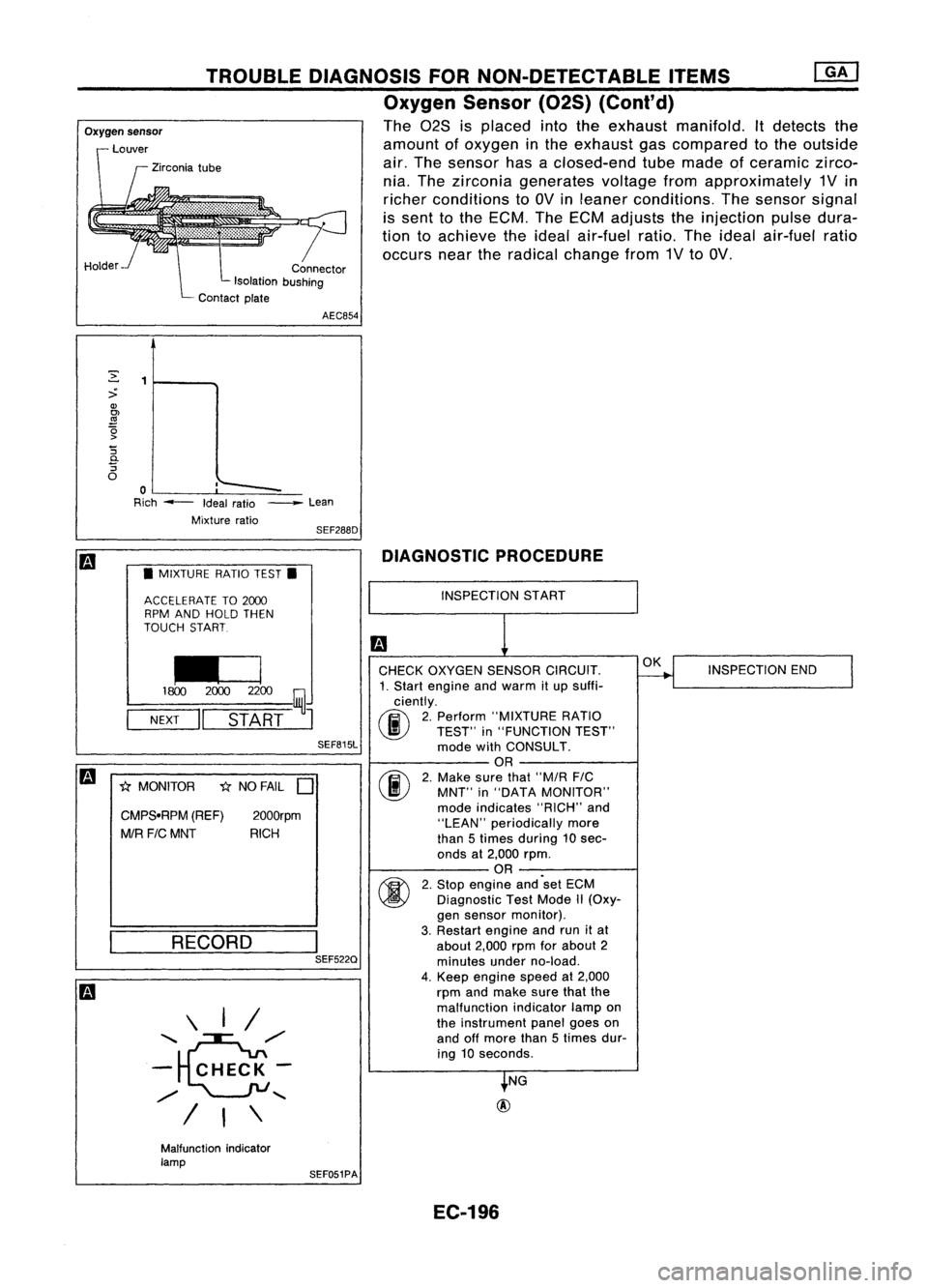
TROUBLEDIAGNOSIS FORNON-DETECTABLE ITEMS
Oxygen Sensor(02S)(Cont'd)
The 028 isplaced intotheexhaust manifold. Itdetects the
amount ofoxygen inthe exhaust gascompared tothe outside
air. The sensor hasaclosed-end tubemade ofceramic zirco-
nia. The zirconia generates voltagefromapproximately 1Vin
richer conditions toOV inleaner conditions. Thesensor signal
is sent tothe ECM. TheECM adjusts theinjection pulsedura-
tion toachieve theideal air-fuel ratio.Theideal air-fuel ratio
occurs neartheradical change from1VtoOV.
r
Connector
Isolation bushing
Contact plate
Oxygen
sensor
Louver
Zirconia tube
Holder AEC854
,'--
~
:>
Q)
OJ
.!!1
~ '5
0-
'5
o
o
Rich --- Idealratio
Mixture ratio_
Lean
SEF288D
m
•MIXTURE RATIOTEST.
ACCELERATE TO2CXXJ
RPM AND HOLD THEN
TOUCH START
~
1800 2CXXJ2200
~J
NEXT
II
START
SEF815L
m
1;{MONITOR 1;{NO FAIL
D
CMPS.RPM (REF)
2000rpm
MIR FICMNT RICH
RECORD \ I/
'~/'
- CHECK-
/
"-
I
I\
I
SEF522Q DIAGNOSTIC
PROCEDURE
INSPECTION START
CHECK OXYGEN SENSORCIRCUIT.
1. Start engine andwarm itup suffi-
ciently.
(F.i\
2.Perform "MIXTURE RATIO
~ TEST"in"FUNCTION TEST"
mode withCONSULT.
OR
(F.i\
2.Make surethat"M/R FIC
\..!!J
MNT"in"DATA MONITOR"
mode indicates "RICH"and
"LEAN" periodically more
than 5times during 10sec-
onds at2,000 rpm.
OR
~ 2.Stop engine and'set ECM
~ Diagnostic TestMode II(Oxy-
gen sensor monitor).
3. Restart engineandrunitat
about 2,000rpmforabout 2
minutes underno-load.
4. Keep engine speedat2,000
rpm andmake surethatthe
malfunction indicatorlampon
the instrument panelgoeson
and offmore than5times dur-
ing 10seconds.
NG
@
OK
INSPECTION END
Malfunction indicator
lamp SEF051PA
EC-196
Page 951 of 1701
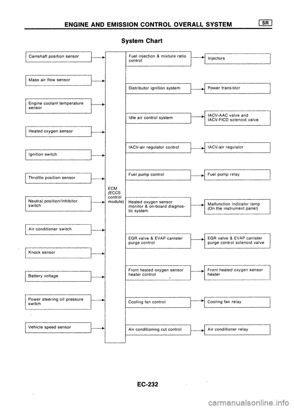
ENGINEANDEMISSION CONTROLOVERALLSYSTEM
System Chart
Camshaft positionsensor Fuel
injection
&
mixture ratio
•
I
I
control Injectors
Mass airflow sensor
I
Distributorignitionsystem
r
~1
Power transistor
Engine coolant temperature
.
sensor
I
IACV-AAC valveand
Idle aircontrol system
IACV-FICDsolenoidvalve
Heated oxygen sensor
I
IACV-airregulator control
~--..j
IACV-air regulator
I
Ignition switch
I
I
Throttle position sensor
~-+
Fuel
pump control Fuel
pump relay
ECM
(ECCS
control
Neutral position/Inhibitor
.
module) Heatedoxygen sensor
switch monitor
&
on-board diagnos-
~-+
Malfunction
indicatorlamp
tic system (On
theinstrument panel)
I
Air conditioner switch
t~
EGRvalve
&
EVAP canister
1---+
EGR
valve
&
EVAP canister
purge control purge
control solenoid valve
Knock sensor
.....
Frontheated oxygen sensor Front
heated oxygen sensor
Battery voltage
.
heater
control heater
I
.
Power steering oilpressure
~
Coolingfancontrol
--
Cooling
fanrelay
switch
Vehicle speedsensor
.....
Airconditioning cutcontrol Air
conditioner relay
EC-232