1995 NISSAN ALMERA N15 checking oil
[x] Cancel search: checking oilPage 1530 of 1701
ENGINEMAINTENANCE
Checking InjectionNozzle(Cont'd)
Nozzle side
Combustion
chamber side
SEF668A Checking IdleSpeed
PREPARATION
1: Make surethatinjection timingiscorrect.
2. Make surethatinjection nozzlesareingood condition.
3. Make surethatthefollowing partsareingood condition.
• Air cleaner clogging
• Glow system
• Engine oiland coolant levels
• Air intake system (Oilfiller cap,oillevel gauge, etc.)
4. Set shift lever in"Neutral" position.Engageparkingbrake
and lock both front andrear wheels withwheel chocks.
5. Turn offair conditioner, lightsandaccessories.
6. Warm upengine tonormal operating temperature.
7. Attach adiesel tachotester.
8. Race engine twoorthree times andcheck idlespeed.
Idle speed (M/T):
700~go rprn
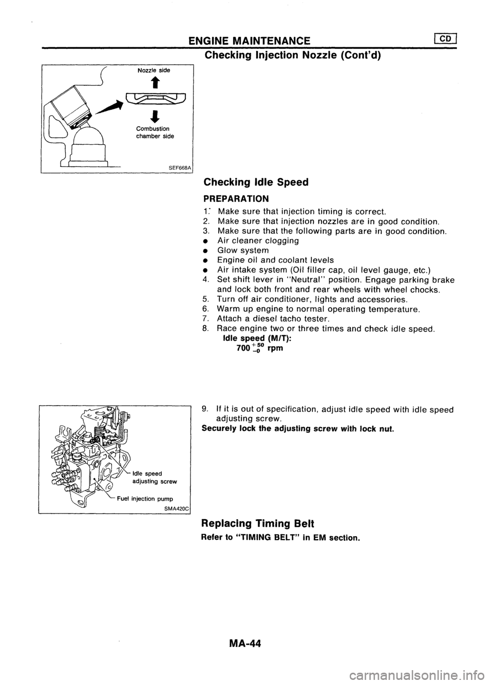
9.
If
itis out ofspecification, adjustidlespeed withidlespeed
adjusting screw.
Securely locktheadjusting screwwithlock nut.
Idle speed
adjusting screw
Fuel injection pump
SMA420C
Replacing TimingBelt
Refer to"TIMING BELT"inEM section.
MA-44
Page 1531 of 1701

CHASSISANDBODY MAINTENANCE
Checking ExhaustSystem
Check exhaust pipes,muffler andmounting forimproper attach-
ment andforleaks, cracks, damage, looseconnections, chafing
and deterioration. •
SMA211A Checking ClutchFluidLevel andLeaks
If fluid level isextremely low,check clutch system forleaks.
SMA449C Checking ClutchSystem
HYDRAULIC TYPE
Check fluidlines andoperating cylinderforimproper
attachment, cracks,damage, looseconnections, chafingand
deterioration.
jJ
I
SMA"",
MECHANICAL TYPE
Check cableandlinks forimproper attachment, chafing,wear
and deterioration.
SMA141A Checking MITOil
• Check thatoilisnot leaking fromtransaxle oraround it.
• Remove speedometer pinionandcheck thattheoillevel L
at vehicle rearside iswithin specification.
Specified
Specifiedoillevel (Dimension L):
oil level
RS5F30A58-66 mm (2.28 -2.60 in)
RS5F31A GA engine 57-66 mm (2.24 -2.60 in)
CD engine 54-61 mm (2.13 -2.40 in)
RS5F32A 39-44 mm (1.54 -1.73 in)
SMT512C
MA-45
Page 1532 of 1701
CHASSISANDBODY MAINTENANCE
Changing
MIT
Oil
1. Drain oilfrom drain plugandrefill withnewgear oil.
2. Check oillevel. (Refer to"Checking
M/T
Oil".)
Oil grade:
API GL-4
Viscosity: See "RECOMMENDED FLUIDSANDLUBRICANTS",
MA-14.
Capacity: RS5F30A 2.8-3.0f
(4-7/8 -5-114
Imppi)
RS5F31A 2.9-3.2£
(5-1/8 -5-518
Imppt)
RS5F32A 3.7-3.9£ (6-112 -
6-7/8
Imppt)
Drain plug:
(OJ:
15-20 N'm (1.5-2.0 kg-m, 11-14 ft-Ib)
6. Check fluidcondition. Iffluid isvery dark orsmells burned,
or contains frictionmaterial (clutches, band,etc.),check
operation ofAlT. Refer toAT section forchecking operation
of AlT.
Checking
AIT
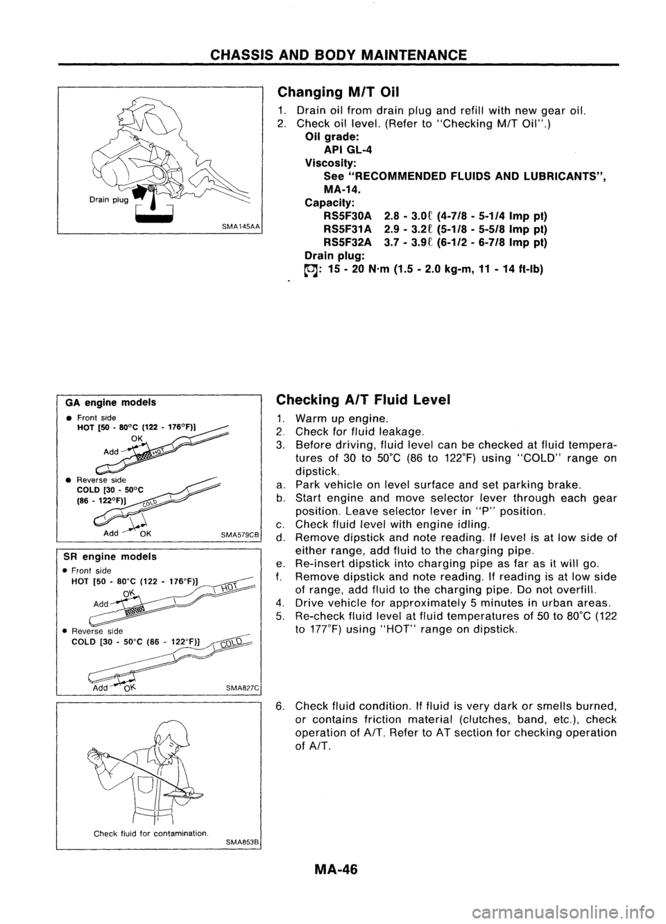
Fluid Level
1. Warm upengine .
2. Check forfluid leakage.
3. Before driving, fluidlevel canbechecked atfluid tempera-
tures of30 to50°C (86to122°F) using"COLD" rangeon
dipstick.
a. Park vehicle onlevel surface andsetparking brake.
b. Start engine andmove selector leverthrough eachgear
position. Leaveselector leverin"P" position.
c. Check fluidlevel withengine idling.
d. Remove dipstickandnote reading. Iflevel isat low side of
either range, addfluid tothe charging pipe.
e. Re-insert dipstickintocharging pipeasfar asitwill go.
f.
Remove dipstickandnote reading.
If
reading isat low side
of range, addfluid tothe charging pipe.Donot overfill.
4. Drive vehicle forapproximately 5minutes inurban areas.
5. Re-check fluidlevel atfluid temperatures of50 to80°C (122
to 177°F) using"HOT" rangeondipstick.
SMA827C
SMA579CB
GA
engine models
• Front side
HOT [50•80°C (122•176°F))
OK
SR engine models
• Front side
HOT [50•80"C (122-176"F)]
o'f..
Check fluidforcontamination.
SMA853B
MA-46
Page 1537 of 1701
CHASSISANDBODY MAINTENANCE
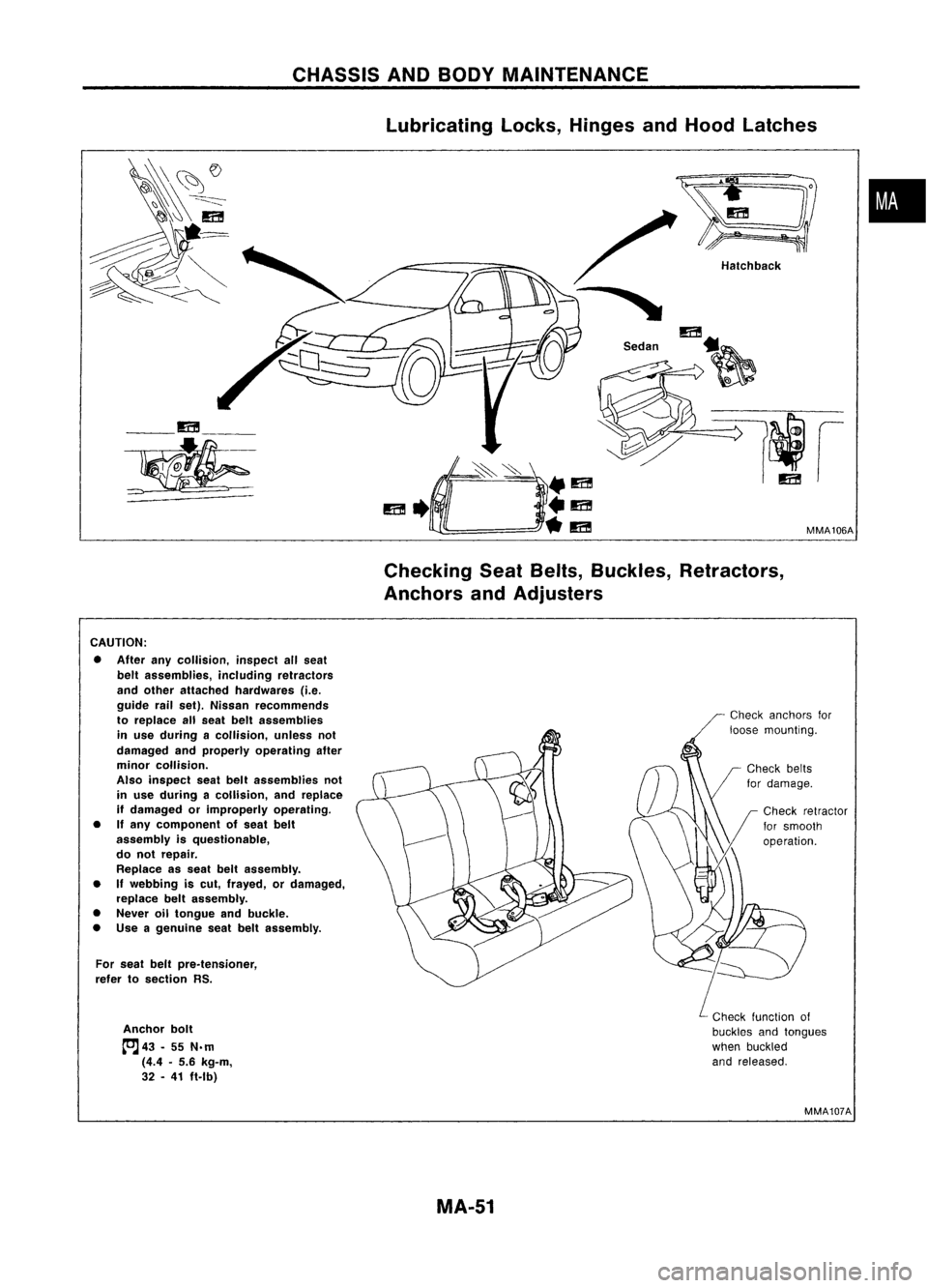
lubricating locks,Hinges andHood latches
•
MMA106A
Hatchback
/
"
m
S.d" ~
__ m__
~
CheckingSeatBelts, Buckles, Retractors,
Anchors andAdjusters
CAUTION: • After anycollision, inspectallseat
belt assemblies, includingretractors
and other attached hardwares (i.e.
guide railset). Nissan recommends
to replace allseat beltassemblies
in use during acollision, unlessnot
damaged andproperly operating after
minor collision.
Also inspect seatbeltassemblies not
in use during acollision, andreplace
if damaged orimproperly operating.
• Ifany component ofseat belt
assembly isquestionable,
do not repair.
Replace asseat beltassembly.
• If
webbing iscut, frayed, ordamaged,
replace beltassembly.
• Never oiltongue andbuckle.
• Use agenuine seatbeltassembly.
For seat beltpre.tensioner,
refer tosection RS.
Anchor bolt
tcJ
43•55 N.m
(4.4 •5.6 kg-m,
32 •41 ft.lb)
Check
anchors for
loose mounting.
Check function of
buckles andtongues
when buckled
and released.
MMA107A
MA-51
Page 1667 of 1701
STEERINGSYSTEM
SECTIONST
CONTENTS
PRECAUTIONS ANDPREPARATION 2
Precautions 2
Special Service Tools 3
Commercial ServiceTools 4
ON-VEHICLE SERVICE
5
Checking SteeringWheelPlay 5
Checking NeutralPosition onSteering Wheel 5
Front Wheel Turning Angle 5
Checking GearHousing Movement 5
Checking andAdjusting DriveBelts(For
power steering) 6
Checking FluidLevel 6
Checking FluidLeakage 6
Bleeding Hydraulic System 7
Checking SteeringWheelTurning Force(For
power steering) 7
Checking Hydraulic System 8
STEERING WHEElANDSTEERING COLUMN 9
Removal andInstallation 9
Disassembly andAssembly 12
Inspection 13
MANUAL STEERING GEARANDLINKAGE
(Model R24N) 14
Removal
andInstallation 14
Disassembly 15
Inspection 15
Assembly andAdjustment... 16
POWER STEERING GEARANDLINKAGE (Model
PR24AC) 19
Removal andInstallation 19
Disassembly 22
Inspection 22
Assembly ,.. 23
Adjustment 27
POWER STEERING OILPUMP 29
Pre-disassembly Inspection 30
Disassembly 30
Inspection 31
Assembly 31
POWER STEERING OILCOOLER
33
Oil Cooler (Heavy dutykitfor CD20 engine
model) 33
Removal andInstallation 33
SERVICE DATAANDSPECIFICATIONS
(505)34
General Specifications 34
Inspection andAdjustment 34
•
Page 1672 of 1701
ON-VEHICLESERVICE
Checking andAdjusting DriveBelts(Forpower
steering)
Refer to"Checking DriveBelts" for"ENGINE MAINTENANCE"
in MA section.
SST476C
S
r
SST681B Checking
Fluidlevel
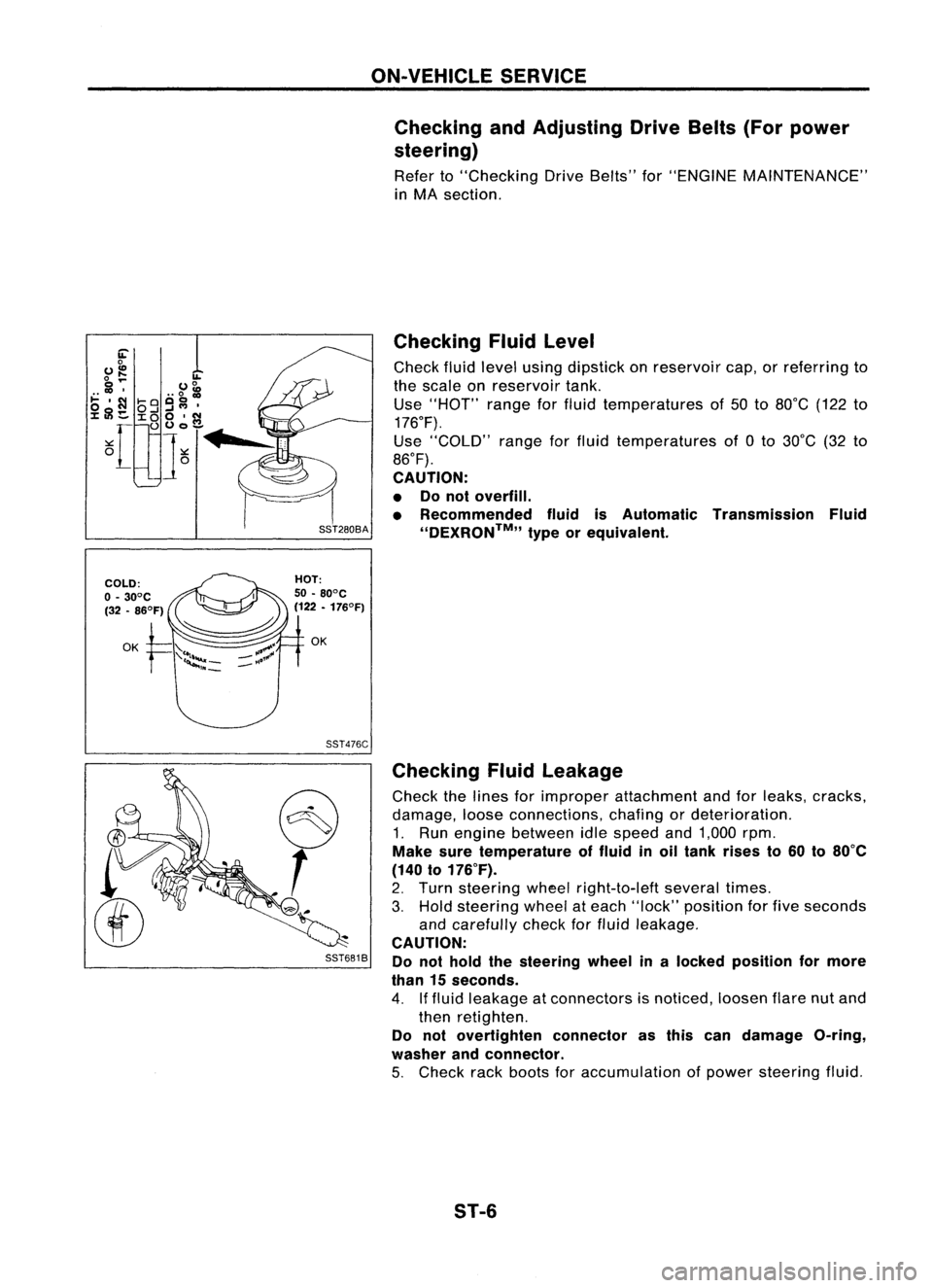
Check fluidlevel using dipstick onreservoir cap,orreferring to
the scale onreservoir tank.
Use "HOT" rangeforfluid temperatures of50 to80°C (122to
176°F).
Use "COLD" rangeforfluid temperatures of0to 30°C (32to
86°F).
CAUTION:
• Donot overfill.
• Recommended fluidisAutomatic Transmission Fluid
''DEXRON™,, typeorequivalent.
Checking Fluidleakage
Check thelines forimproper attachment andforleaks, cracks,
damage, looseconnections, chafingordeterioration.
1. Run engine between idlespeed and1,000 rpm.
Make suretemperature offluid inoil tank rises to60 to80°C
(140 to176°F).
2. Turn steering wheelright-to-Ieft severaltimes.
3. Hold steering wheelateach "lock" position forfive seconds
and carefully checkforfluid leakage.
CAUTION:
Do not hold thesteering wheelinalocked position formore
than 15seconds.
4. Iffluid leakage atconnectors isnoticed, loosenflarenutand
then retighten.
Do not overtighten connectorasthis candamage O-ring,
washer andconnector.
5. Check rackboots foraccumulation ofpower steering fluid.
ST-6
Page 1673 of 1701
SST491B
SST090B ON-VEHICLE
SERVICE
Bleeding Hydraulic System
1. Raise frontendofvehicle untilwheels areclear ofthe
ground.
2. Add fluid intooiltank tospecified level.Thenquickly turn
steering wheelfullytoright andleftand lightly touchsteer-
ing stoppers.
Repeat steering wheeloperation untilfluid level nolonger
decreases.
3. Start engine.
Repeat step2.above.
• Incomplete airbleeding willcause thefollowing tooccur.
When thishappens, bleedairagain.
a. Air bubbles inreservoir tank
b. Clicking noiseinoil pump
c. Excessive buzzinginoil pump
Fluid noise mayoccur inthe valve oroil pump. Thisiscommon
when thevehicle isstationary orwhile turning thesteering
wheel slowly. Thisdoes notaffect theperformance ordurabil-
ity ofthe system.
Checking SteeringWheelTurning Force(For
power steering)
1. Park vehicle onalevel, drysurface andsetparking brake.
2. Start engine.
3. Bring power steering fluiduptoadequate operating temper-
ature. [Make suretemperature offluid isapproximately 60
to 80°C (140to176°F).]
Tires needtobe inflated tonormal pressure.
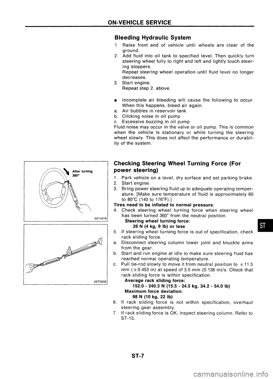
4. Check steering wheelturning forcewhen steering wheel
has been turned 360°from theneutral position.
Steering wheelturning force: •
39 N(4 kg, 9Ib) orless
5.
If
steering wheelturning forceisout ofspecification, check
rack sliding force.
a. Disconnect steeringcolumnlowerjointandknuckle arms
from thegear.
b. Start andrunengine atidle tomake suresteering fluidhas
reached normaloperating temperature.
c. Pull tie-rod slowlytomove itfrom neutral position to
::l::
11.5
mm
(::l::
0.453 in)atspeed of3.5 mm (0.138 in)/s.Check that
rack sliding forceiswithin specification.
Average racksliding force:
152.0 -240.3 N(15.5 -24.5 kg,34.2 -54.0 Ib)
Maximum forcedeviation:
98 N(10 kg, 22Ib)
6.
If
rack sliding forceisnot within specification, overhaul
steering gearassembly.
7. Ifrack sliding forceisOK, inspect steering column.Referto
ST-13.
ST-7
Page 1674 of 1701
ST27091000
.. :Direction ofoil flow Low-pressure
hose SST834-AON-VEHICLE
SERVICE
Checking Hydraulic System
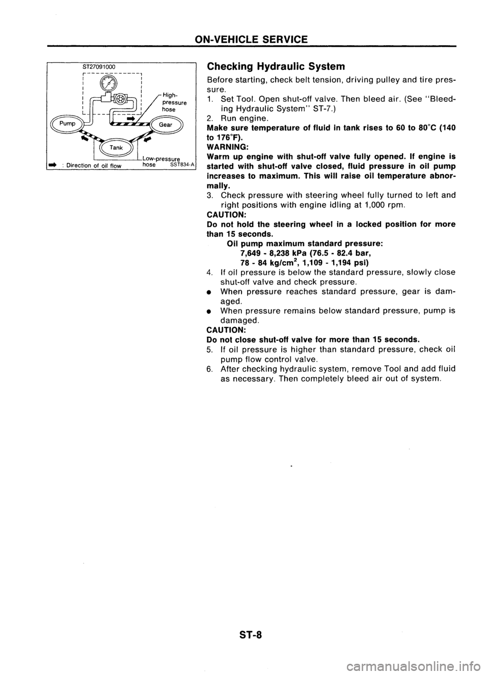
Before starting, checkbelttension, drivingpulleyandtirepres-
sure. 1. Set Tool. Open shut-off valve.Thenbleed air.(See "Bleed-
ing Hydraulic System"ST-7.)
2. Run engine.
Make suretemperature offluid intank rises to60 to80°C (140
to 176°F).
WARNING:
Warm upengine withshut-off valvefullyopened. Ifengine is
started withshut-off valveclosed, fluidpressure inoil pump
increases tomaximum. Thiswillraise oiltemperature abnor-
mally.
3. Check pressure withsteering wheelfullyturned toleft and
right positions withengine idlingat1,000 rpm.
CAUTION:
Do not hold thesteering wheelinalocked position formore
than 15seconds.
Oil pump maximum standardpressure:
7,649 -8,238 kPa(76.5 .82.4 bar,
78 -84 kg/cm
2,
1,109-1,194 psi)
4.
If
oil pressure isbelow thestandard pressure, slowlyclose
shut-off valveandcheck pressure.
• When pressure reachesstandard pressure, gearisdam-
aged.
• When pressure remainsbelowstandard pressure, pumpis
damaged.
CAUTION: Do not close shut-off valveformore than15seconds.
5.
If
oil pressure ishigher thanstandard pressure, checkoil
pump flowcontrol valve.
6. After checking hydraulic system,removeToolandaddfluid
as necessary. Thencompletely bleedairout ofsystem.
S1-8