1995 NISSAN ALMERA N15 checking oil
[x] Cancel search: checking oilPage 1180 of 1701
ENGINEMECHANICAL
SECTION
EM
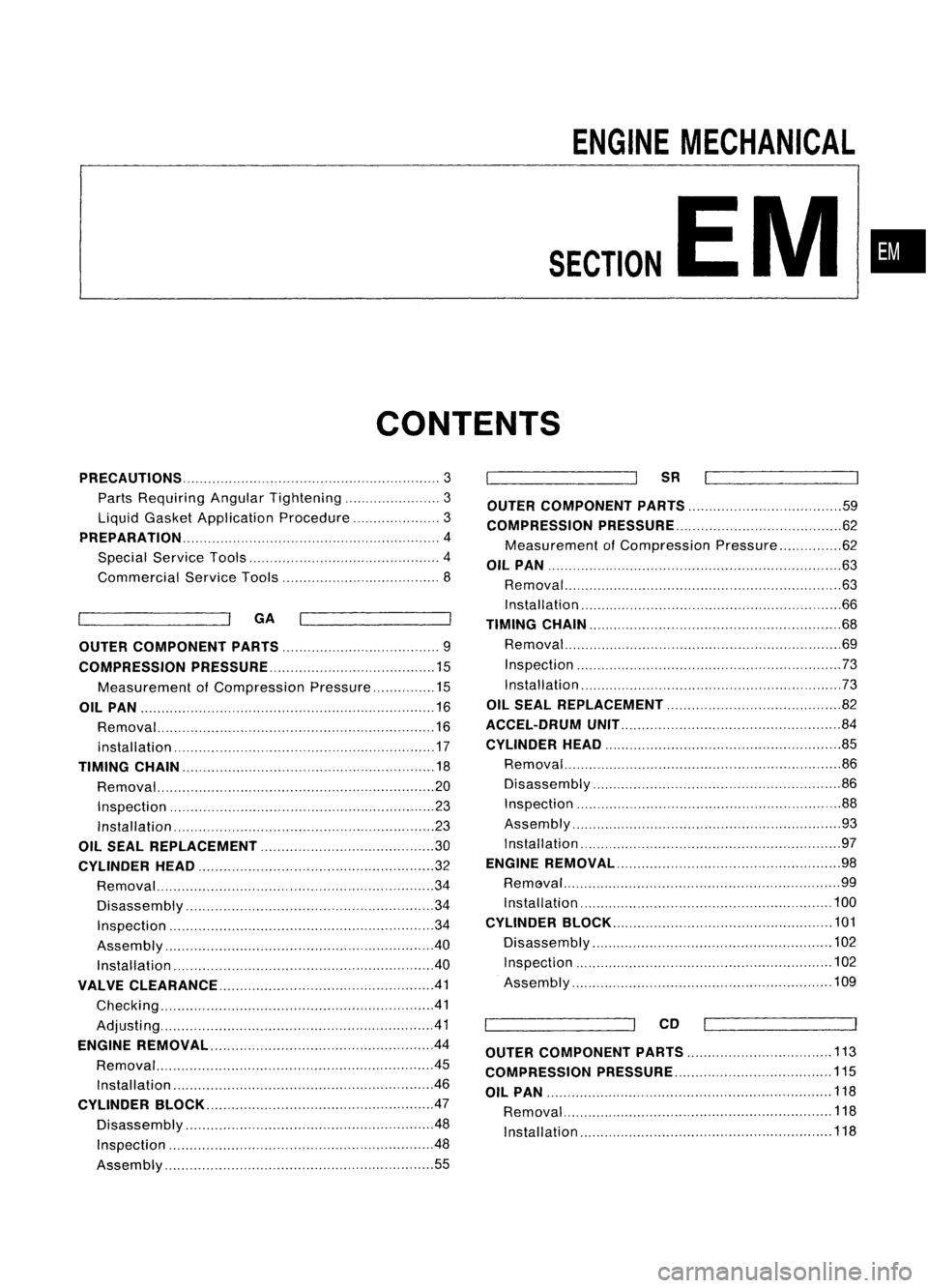
CONTENTS
•
PRECAUTIONS
3
Parts Requiring AngularTightening 3
Liquid Gasket Application Procedure 3
PREPARATION 4
Special Service Tools 4
Commercial ServiceTools 8
GA
OUTER COMPONENT PARTS 9
COMPRESSION PRESSURE 15
Measurement ofCompression Pressure 15
OIL PAN 16
Removal 16
installation 17
TIMING CHAIN
18
Removal. 20
Inspection 23
Installation 23
OIL SEAL REPLACEMENT 30
CYLINDER HEAD 32
Removal 34
Disassembly 34
Inspection 34
Assembly 40
Installation 40
VALVE CLEARANCE 41
Checking 41
Adjusti ng 41
ENGINE REMOVAL .44
Removal 45
Ins taIIat ion " 46
CYLINDER BLOCK 47
Disassembly 48
Inspection 48
Assembly 55
SR
OUTER COMPONENT PARTS 59
COMPRESSION PRESSURE 62
Measurement ofCompression Pressure 62
OIL PAN
63
Removal 63
Installation ,66
TIMING CHAIN 68
Removal 69
Inspection 73
Installation ,73
OIL SEAL REPLACEMENT 82
ACCEL-DRUM UNIT 84
CYLINDER HEAD
85
Removal 86
Disassembly 86
Inspection 88
Assembly 93
Installation , 97
ENGINE REMOVAL 98
RemGval 99
Installation "100
CYLINDER BLOCK 101
Disassembly 102
Inspection , 102
Assembly 109
CD
OUTER COMPONENT PARTS
113
COMPRESSION PRESSURE 115
OIL PAN 118
Removal 118
Installation 118
Page 1194 of 1701
COMPRESSIONPRESSURE
20
mm
(O.79 In)dls.
Use compressor testerwhose end(rubber
portion) isless than 20mm (0.79 in)dia.
Otherwise, itmay becaught bycylinder
head during removal.
SEM387CMeasurement
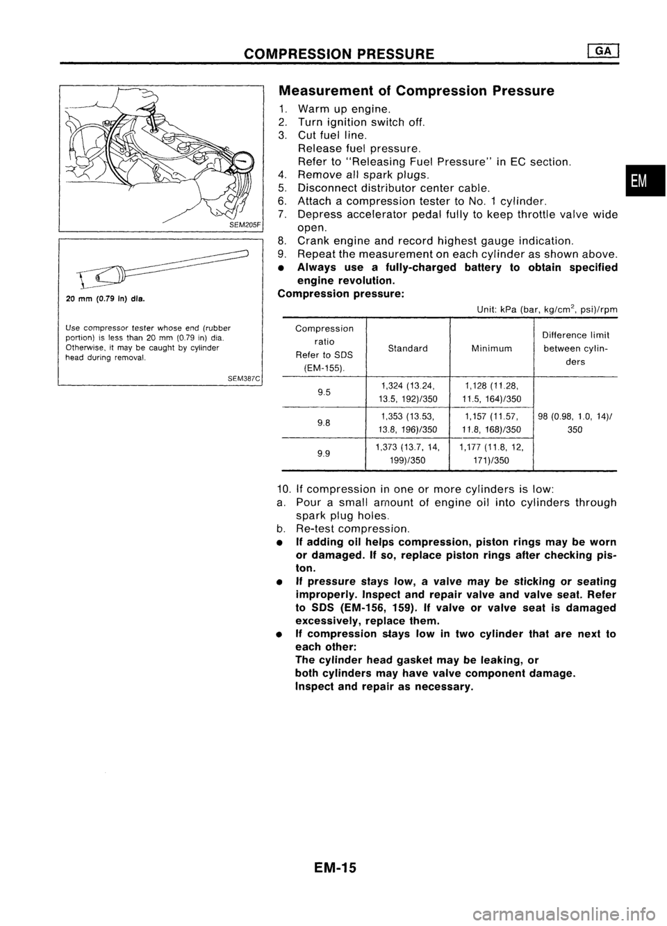
ofCompression Pressure
1. Warm upengine.
2. Turn ignition switchoff.
3. Cut fuel line.
Release fuelpressure.
Refer to"Releasing FuelPressure" inEC section. •
4. Remove allspark plugs.
5. Disconnect distributorcentercable.
6. Attach acompression testertoNO.1 cylinder.
7. Depress accelerator pedalfullytokeep throttle valvewide
open.
8. Crank engine andrecord highest gaugeindication.
9. Repeat themeasurement oneach cylinder asshown above.
• Always useafully-charged batterytoobtain specified
engine revolution.
Compression pressure:
Unit:kPa(bar, kg/cm
2,
psi)/rpm
Compression Differencelimit
ratio
Standard
Refer toSOS Minimum
betweencylin-
(EM-155). ders
9.5 1,324
(13.24, 1,128(11.28,
13.5, 192)/350 11.5,164)/350
9.8 1,353
(1353, 1,157(11.57, 98(0.98, 1.0,14)/
13.8, 196)/350 11.8,168)/350
350
9.9 1,373
(13.7, 14, 1,177(11.8,12,
199)/350 171)/350
10.
If
compression inone ormore cylinders islow:
a. Pour asmall amount ofengine oilinto cylinders through
spark plugholes.
b. Re-test compression,
• Ifadding oilhelps compression, pistonringsmaybeworn
or damaged. Ifso, replace pistonringsafterchecking pis-
ton.
• Ifpressure stayslow,avalve maybesticking orseating
improperly. Inspectandrepair valveandvalve seat.Refer
to SOS (EM-156, 159).Ifvalve orvalve seatisdamaged
excessively, replacethem.
• Ifcompression stayslowintwo cylinder thatarenext to
each other:
The cylinder headgasket maybeleaking, or
both cylinders mayhave valve component damage.
Inspect andrepair asnecessary.
EM-15
Page 1205 of 1701
Intakeside
o~ ~
~NO.5~
~ ~No. 4~
~ "'DNo. 3"~
L
"\J;;\
No.2
~V~NO'
~~FronOt mark~
Front ......., TIMING
CHAIN
Installation (Cont'd)
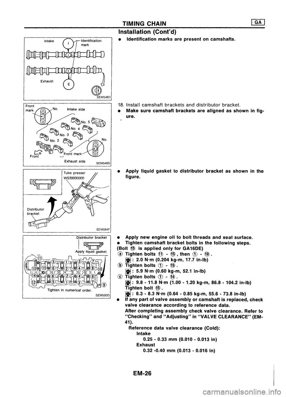
• Identification marksarepresent oncamshafts.
18. Install camshaft bracketsanddistributor bracket.
• Make surecamshaft bracketsarealigned asshown infig-
ure.
Exhaust side
SEM549D
Distributor bracket
I~
Apply liquidgasket.
@
@
@
rl~FL~~I~~~~
),i
o)(oo~-.'.-
0l1..0)(
0
~ .@/~
o'(!l@
@
cID
CD~cID
oc1)
1
0
@
Tighten innumerical order.
SEM550D
•
Apply liquidgasket todistributor bracketasshown inthe
figure.
• Apply newengine oiltobolt threads andseat surface.
• Tighten camshaft bracketboltsinthe following steps.
(Bolt
@>
isapplied onlyforGA16DE)
@
Tighten bolts
@-
@>,
then
CD-
@).
~: 2.0N'm (0.204 kg-m,17.7in-Ib)
@
Tighten bolts
CD-
@>.
~: 5.9N'm (0.60 kg-m, 52.1in-Ib)
@
Tighten bolts
CD-
@.
~: 9.8-11.8 N'm (1.00 -1.20 kg-m, 86.8-104.2 in-Ib)
Tighten bolt
@>.
~: 6.3-8.3 N'm (0.64 -0.85 kg-m, 55.6-73.8 in-Ib)
• Ifany part ofvalve assembly orcamshaft isreplaced, check
valve clearance accordingtoreference data.
After completing assemblycheckvalveclearance. Referto
"Checking" and"Adjusting" in"VALVE CLEARANCE" (EM-
41).
Reference datavalve clearance (Cold):
Intake
0.25 -0.33 mm(0.010 -0.013 in)
Exhaust
0.32 -0.40 mm(0.013 -0.016 in)
EM-26
Page 1241 of 1701
COMPRESSIONPRESSURE
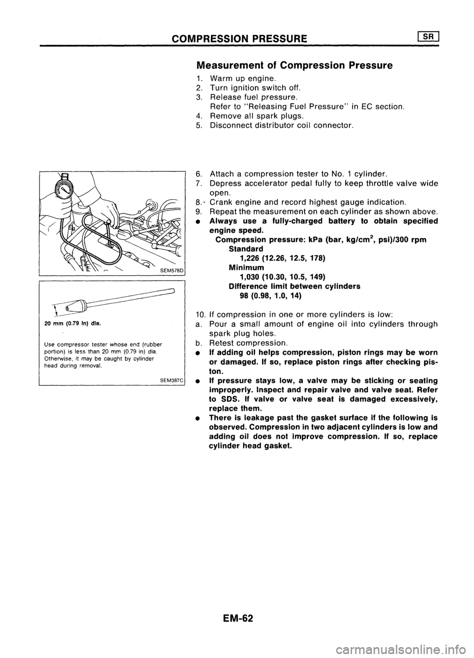
Measurement ofCompression Pressure
1. Warm upengine.
2. Turn ignition switchoff.
3. Release fuelpressure.
Refer to"Releasing FuelPressure" inEC section.
4. Remove allspark plugs.
5. Disconnect distributorcoilconnector.
20
mm (0.79
In)dls.
Use compressor testerwhose end(rubber
portion) isless than 20mm (0.79 in)dia.
Otherwise. itmay becaught bycylinder
head during removal.
SEM387C6.
Attach acompression testertoNO.1 cylinder.
7. Depress accelerator pedalfullytokeep throttle valvewide
open.
8.' Crank engine andrecord highest gaugeindication.
9. Repeat themeasurement oneach cylinder asshown above.
• Always useafully-charged batterytoobtain specified
engine speed.
Compression pressure:kPa(bar, kg/cm
2,
psi)/300 rpm
Standard 1,226 (12.26, 12.5,178)
Minimum 1,030 (10.30, 10.5,149)
Difference limitbetween cylinders
98 (0.98, 1.0,14)
10. Ifcompression inone ormore cylinders islow:
a. Pour asmall amount ofengine oilinto cylinders through
spark plugholes.
b. Retest compression.
• If
adding oilhelps compression, pistonringsmaybeworn
or damaged.
If
so, replace pistonringsafterchecking pis-
ton.
• Ifpressure stayslow,avalve maybesticking orseating
improperly. Inspectandrepair valveandvalve seat.Refer
to
50S.
If
valve orvalve seatisdamaged excessively,
replace them.
• There isleakage pastthegasket surface ifthe following is
observed. Compression intwo adjacent cylinders islow and
adding oildoes notimprove compression.
If
so, replace
cylinder headgasket.
EM-62
Page 1355 of 1701
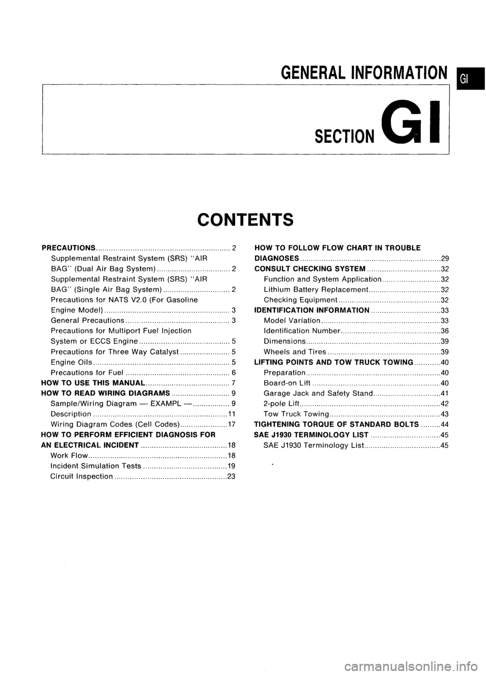
GENERALINFORMATION •
SECTION
G
I
CONTENTS
PRECAUTIONS 2
Supplemental RestraintSystem(SRS)"AIR
BAG" (DualAirBag System) 2
Supplemental RestraintSystem(SRS)"AIR
BAG" (Single AirBag System) 2
Precautions forNATS V2.0(ForGasoline
Engine Model) 3
General Precautions 3
Precautions forMultiport FuelInjection
System orECCS Engine 5
Precautions forThree WayCatalyst 5
Engine Oils 5
Precautions forFuel 6
HOW TOUSE THIS
MANUAL 7
HOW TOREAD WIRING DIAGRAMS 9
Sample/Wiring Diagram-EXAMPL - 9
Description 11
Wiring Diagram Codes(CellCodes) 17
HOW TOPERFORM EFFICIENT DIAGNOSIS FOR
AN ELECTRICAL INCIDENT 18
Work Flow 18
Incident Simulation Tests 19
Circuit Inspection 23
HOW
TOFOLLOW FLOWCHART INTROUBLE
DIAGNOSES 29
CONSULT CHECKING SYSTEM
32
Function andSystem Application 32
Lithium BatteryReplacement.. 32
Checking Equipment 32
IDENTIFICATION INFORMATION 33
Model Variation 33
Identification Number 36
Di mens ions 39
Wheels andTires 39
LIFTING POINTSANDTOW TRUCK TOWING ..40
Preparation 40
Board-on
Lift
40
Garage JackandSafety Stand 41
2-pole Lift 42
Tow Truck Towing 43
TIGHTENING TORQUEOFSTANDARD BOLTS
44
SAE J1930 TERMINOLOGY LIST 45
SAE J1930 Terminology List.. 45
Page 1359 of 1701
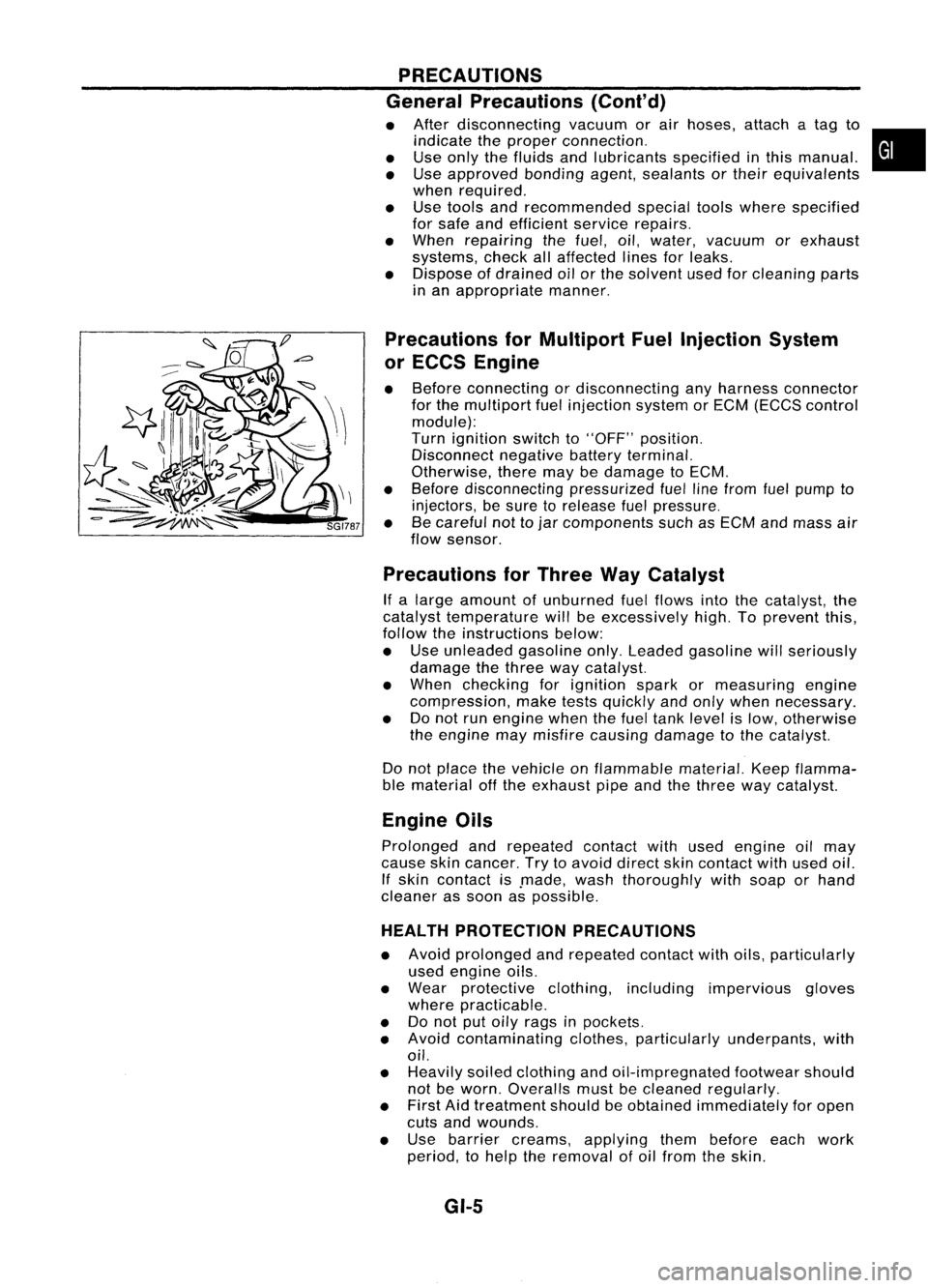
PRECAUTIONS
General Precautions (Cont'd)
• After disconnecting vacuumorair hoses, attachatag to
indicate theproper connection.
• Use only thefluids andlubricants specifiedinthis manual.
• Use approved bondingagent,sealants ortheir equivalents
when required.
• Use tools andrecommended specialtoolswhere specified
for safe andefficient servicerepairs.
• When repairing thefuel, oil,water, vacuum orexhaust
systems, checkallaffected linesforleaks.
• Dispose ofdrained oilorthe solvent usedforcleaning parts
in an appropriate manner.
Precautions forMultiport FuelInjection System
or ECCS Engine
• Before connecting ordisconnecting anyharness connector
for the multiport fuelinjection systemorEGM (EGGS control
module):
Turn ignition switchto"OFF" position.
Disconnect negativebatteryterminal.
Otherwise, theremaybedamage toEGM.
• Before disconnecting pressurizedfuellinefrom fuelpump to
injectors, besure torelease fuelpressure.
• Becareful nottojar components suchasEGM andmass air
flow sensor.
Precautions forThree WayCatalyst
If a large amount ofunburned fuelflows intothecatalyst, the
catalyst temperature willbeexcessively high.Toprevent this,
follow theinstructions below:
• Use unleaded gasolineonly.Leaded gasoline willseriously
damage thethree waycatalyst.
• When checking forignition sparkormeasuring engine
compression, maketestsquickly andonly when necessary.
• Donot run engine whenthefuel tank level islow, otherwise
the engine maymisfire causing damage tothe catalyst.
Do not place thevehicle onflammable material.Keepflamma-
ble material offthe exhaust pipeandthethree waycatalyst.
Engine Oils
Prolonged andrepeated contactwithused engine oilmay
cause skincancer. Trytoavoid direct skincontact withused oil.
If skin contact is.made, washthoroughly withsoap orhand
cleaner assoon aspossible.
HEALTH PROTECTION PRECAUTIONS
• Avoid prolonged andrepeated contactwithoils, particularly
used engine oils.
• Wear protective clothing,including impervious gloves
where practicable.
• Donot putoily rags inpockets.
• Avoid contaminating clothes,particularly underpants, with
oil.
• Heavily soiledclothing andoil-impregnated footwearshould
not beworn. Overalls mustbecleaned regularly.
• First Aidtreatment shouldbeobtained immediately foropen
cuts andwounds.
• Use barrier creams, applying thembefore eachwork
period, tohelp theremoval ofoil from theskin.
GI-5
•
Page 1362 of 1701
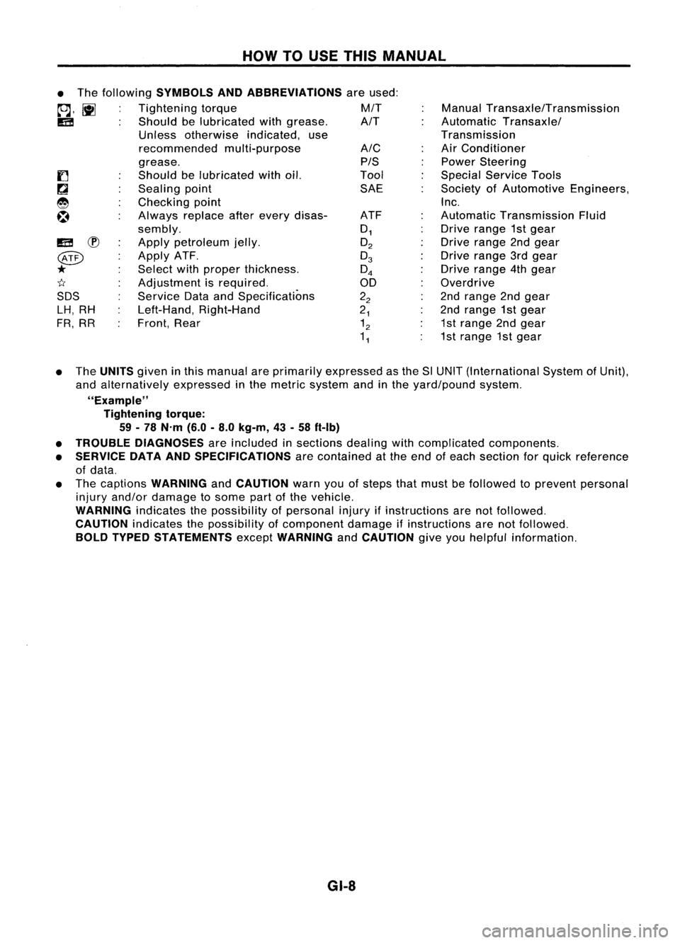
HOWTOUSE THIS MANUAL
ManualTransaxle/Transmission
Automatic Transaxle/
Transmission
Air Conditioner
Power Steering
Special Service Tools
Society ofAutomotive Engineers,
Inc.
Automatic Transmission Fluid
Drive range 1stgear
Drive range 2ndgear
Drive range 3rdgear
Drive range 4thgear
Overdrive
2nd range 2ndgear
2nd range 1stgear
1st range 2ndgear
1st range 1stgear
A/C
PIS
Tool SAE
ATF
0
1
O
2
0
3
0
4
00
2
2
2
1
1
2
1
1
•
The following
SYMBOLS ANDABBREVIATIONS
areused:
to;J,
l\tI
Tightening torque M/T
IE!
Shouldbelubricated withgrease. A/T
Unless otherwise indicated,use
recommended multi-purpose
grease.
Should belubricated withoil.
Sealing point
Checking point
Always replaceafterevery disas-
sembly.
Apply petroleum jelly.
Apply ATF.
Select withproper thickness.
Adjustment isrequired.
Service DataandSpecifications
Left-Hand, Right-Hand
Front, Rear
IE!
~
@
*
1I
SDS LH, RH
FR, RR
• The
UNITS
giveninthis manual areprimarily expressed asthe SlUNIT (International SystemofUnit),
and alternatively expressedinthe metric system andinthe yard/pound system.
"Example" Tightening torque:
59 -78 N'm (6.0-8.0 kg-m, 43-58 ft-Ib)
• TROUBLE DIAGNOSES
areincluded insections dealingwithcomplicated components.
• SERVICE DATAANDSPECIFICATIONS
arecontained atthe end ofeach section forquick reference
of data.
• The captions
WARNING
and
CAUTION
warnyouofsteps thatmust befollowed toprevent personal
injury and/or damage tosome partofthe vehicle.
WARNING
indicatesthepossibility ofpersonal injuryifinstructions arenotfollowed.
CAUTION
indicatesthepossibility ofcomponent damageifinstructions arenotfollowed.
BOLD TYPED STATEMENTS
except
WARNING
and
CAUTION
giveyouhelpful information.
GI-8
Page 1422 of 1701
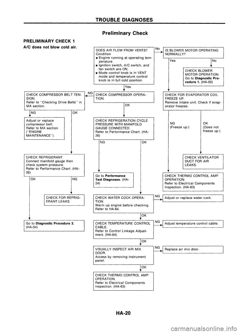
TROUBLEDIAGNOSES
Preliminary Check
PRELIMINARY CHECK1
Ale
does notblow coldair.
DOESAIRFLOW FROM VENTS?
Condition
• Engine running atoperating tem-
perature .
• Ignition switch,AICswitch, and
fan switch areON.
• Mode control knobisin VENT
mode andtemperature control
knob isinfull cold position.
Yes IS
BLOWER MOTOROPERATING
NORMALLY?
Yes
CHECKBLOWER
MOTOR OPERATION.
Go toDiagnostic Pro-
cedure 1.(HA-50)
CHECK COMPRESSOR BELTTEN-
SION. Refer to"Checking DriveBelts" in
MA section.
CHECK REFRIGERANT.
Connect manifold gaugethen
check system pressure.
Refer toPerformance Chart.(HA-
26)
NG CHECK
THERMO CONTROL AMP.
OPERATION.
Refer toElectrical Components
Inspection. (HA-63)
CHECK
FOREVAPORATOR COIL
FREEZE UP.
Remove intakeunit.Check ifevap-
orator freezes.
NG OK
(Freeze up.) (Doesnot
freeze up.)
CHECK VENTILATOR
DUCT FORAIR
LEAKS.
OK
Go toPerformance
Test Diagnoses. (HA-
24)
NG
CHECK
REFRIGERATION CYCLE
PRESSURE WITHMANIFOLD
GAUGE CONNECTED.
Refer toPerformance Chart.(HA-
26) OK
CHECK
COMPRESSOR OPERA-
TION.
OK
OK NG
Adjust orreplace
compressor belt.
Refer toMA section
("ENGINE
MAINTENANCE").
CHECKFORREFRIG-
ERANT LEAKS CHECK
WATER COCKOPERA-
TION.
Warm upengine beforechecking.
Refer toHA-64.
NG
Adjust orreplace watercock.
OK
Go toDiagnostic Procedure3.
(HA-54) CHECK
TEMPERATURE CONTROL
CABLE.
Refer toControl Linkage Adjust-
ment. (HA-64) NG
Adjust temperature controlcable.
OK
VISUALLY INSPECTAIRMIX
DOOR.
Access byremoving instrument
panel. NG
Replace airmix door.
OK
CHECK THERMO CONTROL AMP.
OPERATION. Refer toElectrical Components
Inspection. (HA-63)
HA-20