Page 423 of 1701

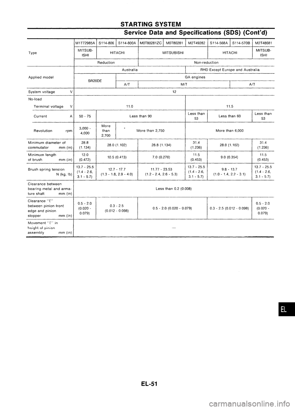
STARTINGSYSTEM
Service DataandSpecifications (SOS)(Cont'd)
M1T72985A S114-806S114-800A
MOT80281ZC
I
MOT80281 M2T49282
S114-568A
I
S114-570B M2T48681
Type MITSUB-
HITACHI MITSUBISHI HITACHIMITSUB-
ISH I ISHI
Reduction Non-reduction
Australia RHD
Except Europe andAustralia
Applied model GA
engines
SR20DE
I
A/T
M/T
AIT
System voltage
V
12
No-load Terminal voltage
V
11.0 11.5
Current A50-75 Less
than90 Less
than
Lessthan60 Less
than
53 53
3,000 - More
.
Revolution rpm
4,000 than
More
than2,750 Morethan6,000
2,700
Minimum diameterof 28.8
280(1.102) 28.8(1.134) 314
28.0(1.102) 314
commutator mm(in) (1.134)
(1.236)
(1236)
Minimum length 12.0
10.5(0413) 7.0
(0.276) 11.5
90(0.354) 11.5
of brush mm(in) (0472) (0453)
(0453)
Brush spring tension 13.7
-25.5
12.7-17.7 11.77-23.53 13.7
-25.5
9.8-13.7 137
-25.5
(14 -2.6, (14
-2.6, (1.4-2.6,
N (kg, Ib)
3.1-5.7) (1.3
-1.8, 2.9-4.0) (1.2-24, 2.6-5.3)
3.1-5.7) (1.0
-14, 2.2-31)
3.1.5.7)
Clearance between
bearing metalandarma- Lessthan0.2(0.008)
ture shaft mm(in)
Clearance"
C"
0.5-2.0 0.5
-2.0
between pinionfront
(0.020- 0.3
-25
05-2.0 (0.020 -0.079) 0.3-2.5 (0.012 -0.098) (0.020-
edge andpinion
0.079)(0.012
-0.098)
0.079)
stopper mm
(in)
Movement
'T'
in
heigh\. atpinion
-
assembly
mm(in)
EL-51
•
Page 440 of 1701
HEADLAMP-Daytime LightSystem -
Operation (Daytimelightsystem)
The headlamps' lowbeam andclearance, license,tailand illu-
mination lampsautomatically turnonafter starting theengine
with lighting switchin"OFF" position.
Lighting switchoperations otherthantheabove arethesame
as conventional lightsystems.
Engine With
engine stopped Withengine running
OFF
1ST2ND
OFF
1ST2ND
Lighting switch
B
C
A
B
C
B
C
A
B
C
B
C
A
B
C
A AA
High beam
XX
0
X
X
0
0
X
0
X
X
0
XX
0
0
X
0
Headlamp
0
0
()
0
()
Low beam
X
XX
XX
X
X
X
XXXX X
Clearance andtaillamp
X
XX
0
0
0
0
00
0
0
0
0
00
0
0
0
License andinstrument illumination lamp
X
XX
0 0
0
0
0
0
0
0 00
0
0()
0
0
0: Lamp "ON"
X: Lamp "OFF"
o :
Added functions
EL-68
Page 446 of 1701
HEADLAMP-Daytime LightSystem -
Trouble Diagnoses (DaytimeLight)
DAYTIME LIGHTCONTROL UNITINSPECTION TABLE
(Input/output operationsignal)
INPUT
(1)/
Voltage
(V)
Terminal No. Connections
OUTPUT
(0)
Operated
condition (Approximate
values)
Power source for
1 illumination
&
tail
- -
12
lamp
2 Power
source for
12
- -
head lamp LH
3
Power
source for
12
-
-
head lamp RH
ON(daytime lightoperating')
12
4
HeadlampRH
0
OFF 0
ON (daytime lightoperating') 12
5
HeadlampLH
0
OFF 0
START 12
6
Startsignal
I
Ignitionswitch
ON,ACC orOFF
0
ON orSTART
12
7
Powersource
-
Ignition
switch
ACCorOFF
0
Alternator "L"ter- Running
12
8
I
Engine
minal Stopped0
9 Ground
- - -
Illumination
&
tail ON
(daytime lightoperating')
12
10 lamp
0
OFF 0
1ST.2ND position
12
11 Lightingswitch
I
OFF 0
': Daytime lightoperating: Lightingswitchin"OFF" position withengine running.
EL-74
Page 453 of 1701

HEADLAMP-Headlamp AimingControl -
Reversing
relay
Thermistor
Reversing
relay
Thermistor
Reversing
relay
::- Thermistor
+
BATIERY
A o
1
2
3
SEL465M
+
BATIERY
o
1
2
3
SEL364P
+
BATIERY
o
1
2
3
SEL365P Description
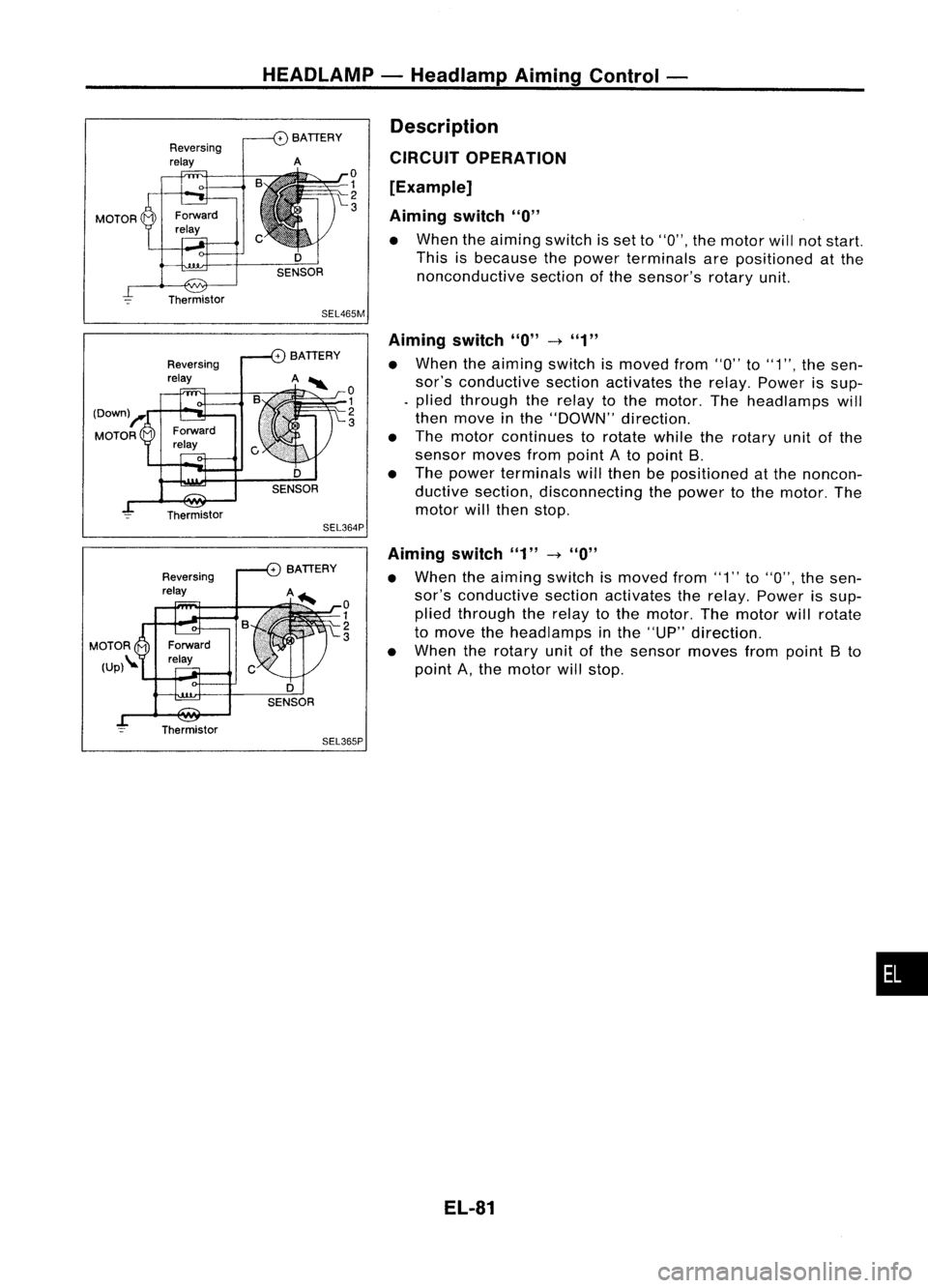
CIRCUIT OPERATION
[Example]
Aiming switch
"0"
• When theaiming switchisset to"0", themotor willnotstart.
This isbecause thepower terminals arepositioned atthe
nonconductive sectionofthe sensor's rotaryunit.
Aiming switch
"0"
-t
"1"
• When theaiming switchismoved from"0"to"1", thesen-
sor's conductive sectionactivates therelay. Power issup-
. plied through therelay tothe motor. Theheadlamps will
then move inthe "DOWN" direction.
• The motor continues torotate whiletherotary unitofthe
sensor movesfrompoint Ato point B.
• The power terminals willthen bepositioned atthe noncon-
ductive section, disconnecting thepower tothe motor. The
motor willthen stop.
Aiming switch"1"
-t
"0"
• When theaiming switchismoved from"1"to"0", thesen-
sor's conductive sectionactivates therelay. Power issup-
plied through therelay tothe motor. Themotor willrotate
to move theheadlamps inthe "UP" direction.
• When therotary unitofthe sensor movesfrompoint Bto
point A,the motor willstop.
EL-81
•
Page 523 of 1701

Ohmmeter- + WARNING
LAMPSANDBUZZER
Oil Pressure SwitchCheck
Oil pressure
Continuity
kPa (bar, kg/cm
2,
psi)
More than10-20
NO
Engine
start
(0.10-0.20, 0.1-0.2, 1.4-2.8)
Less than10-20
YES
Engine
stop
(0.10-0.20, 0.1-0.2, 1.4-2.8)
SEL748K
Test lamp 3.4WON
\ ,I
"
/
Ballery
Test lamp 3.4W OFF
~0
CD
Ballery
Gasoline MEL623D
SEL901F
Check
thecontinuity betweentheterminals ofoil pressure
switch andbody ground.
Fuel Warning LampSensor Check
• Itwill take ashort timeforthe bulb tolight.
Diode Check
• Check continuity usinganohmmeter.
• Diode isfunctioning properlyiftest results areasshown in
the figure atleft.
NOTE:
Specification mayvary depending onthe type oftester. Before
performing thisinspection, besure torefer tothe instruction
manual forthe tester tobe used.
• Diodes forwarning lampsarebuilt intothecombination
meter printed circuit.
Refer to"Combination Meter"(EL-127).
Warning BuzzerUnit
• Seat beltwarning lampiscontrolled bythe warning buzzer
unit.
Refer to"Warning Buzzer"(EL-152).
EL-151
•
Page 551 of 1701

.WIPER ANDWASHER
SEL244P Headlamp
WiperMotorCheck
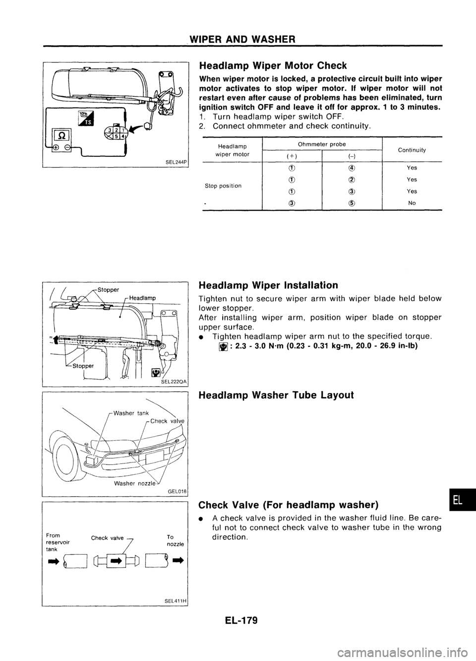
When wiper motor islocked, aprotective circuitbuiltintowiper
motor activates tostop wiper motor. Ifwiper motor willnot
restart evenaftercause ofproblems hasbeen eliminated, turn
ignition switchOFFandleave itoff for approx. 1to 3minutes.
1. Turn headlamp wiperswitch OFF.
2. Connect ohmmeter andcheck continuity.
Headlamp Ohmmeter
probe
Continuity
wiper motor
(+)
H
(!) @
Yes
(!)
@
Yes
Stop position
(!)
CID
Yes
.
CID
@)
No
From
.. 0
c~'..
~'fo
reservoir
tank GEL018
To
nozzle
0"
SEL411H Headlamp
WiperInstallation
Tighten nuttosecure wiperarmwith wiper bladeheldbelow
lower stopper.
After installing wiperarm,position wiperbladeonstopper
upper surface.
• Tighten headlamp wiperarmnuttothe specified torque.
~ :2.3 -3.0 N'm (0.23 -0.31 kg-m, 20.0-26.9 in-Ib)
Headlamp WasherTubeLayout
Check Valve(Forheadlamp washer)
• Acheck valveisprovided inthe washer fluidline.Becare-
ful not toconnect checkvalvetowasher tubeinthe wrong
direction.
EL-179
•
Page 632 of 1701

NATS(Nissan Anti-Theft System)
Trouble Diagnoses (Cont'd)
• SELF-FUNCTION CHECK•
ECM's IMMU
COMMUNICATION INTERFACE
II
***
***
11[!1
******
___ P_R_IN_T
I
SEL342U
• SELF-FUNCTION CHECK•
ECM's IMMU
COMMUNICATION INTERFACE
******
OK
******
___ P_RI_N_T '
SEL343U IMMU
ismalfunctioning.
Replace IMMU.
Ref. part No.A
00
Perform
initialisation withCON-
SULT.
For theoperation of
initialisation, referto"CONSULT
operation manualNATSV2.0".
m
•SELF-DIAG RESULTS.
0
FAILURE DETECTED TIME
DIFFERENCE OFKEY
0
I
ERASE
"
PRINT
I
SEL344U
ERASE
II
PRINT
I
SEL372U
•
C/U
INITIALISATION
INITIALISATION
STOPPED orFAILED
TURN IGNKEY SW"OFF"
AND "ON" AFTER CON-
FIRMING SELF-DIAG
RESULTS, PERFORM C/U
INITIALISATION AGAIN.
•
DIAGNOSTIC
PROCEDURE 4
Self-diagnostic results:
"DIFFERENCE OFKEY" displayed onCONSULT screen
m
00
Confirm
SELF-DIAGNOSTIC
RESULTS "DIFFERENCE OF
KEY" displayed onCONSULT
screen.
t
K
Initialisation
I!J
incompleted •
00
Perform
initialisation withCON- or
failed
IMMUismal-
SULT . with
CON-
functioning.
Re-register allNATS ignition keySULT
ReplaceIMMU.
IDs. Ref.
part No.A
For theoperation ofinitialisation,
refer to"CONSULT operation
manual NATSV2.0".
l,nitialisation completed
Start engine.
~
END
00
Perform
initial isa-
(Ignition keyIDwas unregistered.) tion
with CON-
Ref. part No.0 SULT.
For theoperation
of initialisation,
refer to"CON-
SUL Toperation
manual NATS
V2.0"
EL-260
Page 635 of 1701

SEL490U
IMMU
connector@
NATS
(Nissan Anti-Theft System)
Trouble Diagnoses (Cont'd)
CID
II
1
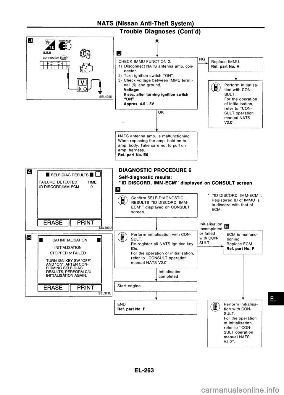
CHECK IMMUFUNCTION 2. NG
Replace IMMU.
1) Disconnect NATSantenna amp.con-
r---+
Ref.part No.A
nector.
1
2)
Turn ignition switch"ON".
3) Check voltage between IMMUtermi-
nal
@
and ground.
00
Perform
initialisa-
Voltage: tion
with CON-
6 sec. after turning ignition switch SULT.
"ON" Fortheoperation
Approx. 4.5-5V of
initialisation,
refer to"CON-
OK SULToperation
manual NATS
V2.0".
NATS antenna amp.ismalfunctioning.
When replacing theamp. holdonto
amp. body. Takecarenottopull on
amp. harness.
Ref. part No.E6
DIAGNOSTIC PROCEDURE6
*"10 DISCORD, IMM-ECM":
Registered IDofIMMU is
in discord withthatof
ECM.
Confirm
SELF-DIAGNOSTIC
RESULTS "10DISCORD, IMM-
ECM*" displayed onCONSULT
screen.
Self-diagnostic
results:
"ID DISCORD, IMM-ECM" displayedonCONSULT screen
m
00
•
SELF-DIAG RESULTS.
0
FAILURE DETECTED TIME
ID DISCORD,IMM-ECM 0
ERASE
II
PRINT
I
SEL383U
[;]
•
C/U
INITIALISATION
•
INITIALISATION
STOPPED orFAILED
TURN IGNKEY SW"OFF"
AND "ON", AFTER CON-
FIRMING SELF-DIAG
RESULTS, PERFORM C/U
INITIALISATION AGAIN.
ERASE
II
PRINT
I
SEL372U Perform
initialisation withCON-
SULT .
Re-register allNATS ignition key
IDs.
For theoperation ofinitialisation,
refer to"CONSULT operation
manual NATSV2.0".
Initialisation
completed
Start engine.
END
Ref. part No.F Initialisation
[;]
incompleted -
or failed ECMismalfunc-
with CON- tioning.
SUL T ReplaceECM.
Ref. part No.F
Perform initialisa-
tion with CON-
SULT.
For theoperation
of initialisation,
refer to"CON-
SUL Toperation
manual NATS
V2.0".
•
EL-263