1995 NISSAN ALMERA N15 stop start
[x] Cancel search: stop startPage 787 of 1701
TROUBLEDIAGNOSIS -General Description
*
MONITOR
*
NO FAIL
ENG TEMP SEN 80°C
RECORD
Cam follower
lever
o
SEF214N
SEF147N Fast
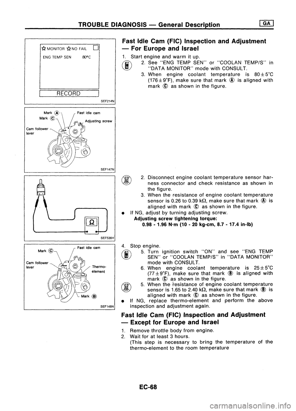
IdleCam (FIC) Inspection andAdjustment
- For Europe andIsrael
1. Start engine andwarm itup.
(ij\
2.See "ENG TEMP SEN"or"COOLAN TEMP/S"in
~ "DATAMONITOR" modewithCONSULT.
3. When engine coolant temperature is80:l: 5°C
(176:l:9°F), makesurethatmark @isaligned with
mark ~asshown inthe figure.
SEF536H •
2.
Disconnect enginecoolant temperature sensorhar-
ness connector andcheck resistance asshown in
the figure.
3. When theresistance ofengine coolant temperature
sensor is0.26 to0.39 kQ,make surethatmark @is
aligned withmark
@
asshown inthe figure.
If NG, adjust byturning adjusting screw.
Adjusting serewtightening torque:
0.98 -1.96 N.m(10-20 kg-em, 8.7-17.4 in-Ib)
Cam follower
lever Fast
idleearn
Thermo-
element
SEF148N
4.
Stop engine.
rF.i\
5.Turn ignition switch"ON"andsee "ENG TEMP
~ SEN"or"COOLAN TEMP/S"in"DATA MONITOR"
mode withCONSULT.
6. When engine coolant temperature is25:l: 5°C
(77:l: 9°F), make surethatmark
CID
isaligned with
mark @asshown inthe figure.
~ 5.When theresistance ofengine coolant temperature
~ sensoris1.65 to2.40 kQ,make surethatmark
CID
is
aligned withmark
@
asshown inthe figure.
• IfNG, replace thermo-element andperform theabove
inspection andadjustment again.
Fast IdleCam (FIC) Inspection andAdjustment
- Except forEurope andIsrael
1. Remove throttlebodyfromengine.
2. Wait foratleast 3hours.
(This stepisnecessary tobring thetemperature ofthe
thermo-element tothe room temperature
EC-68
Page 793 of 1701
TROUBLEDIAGNOSES -General Description
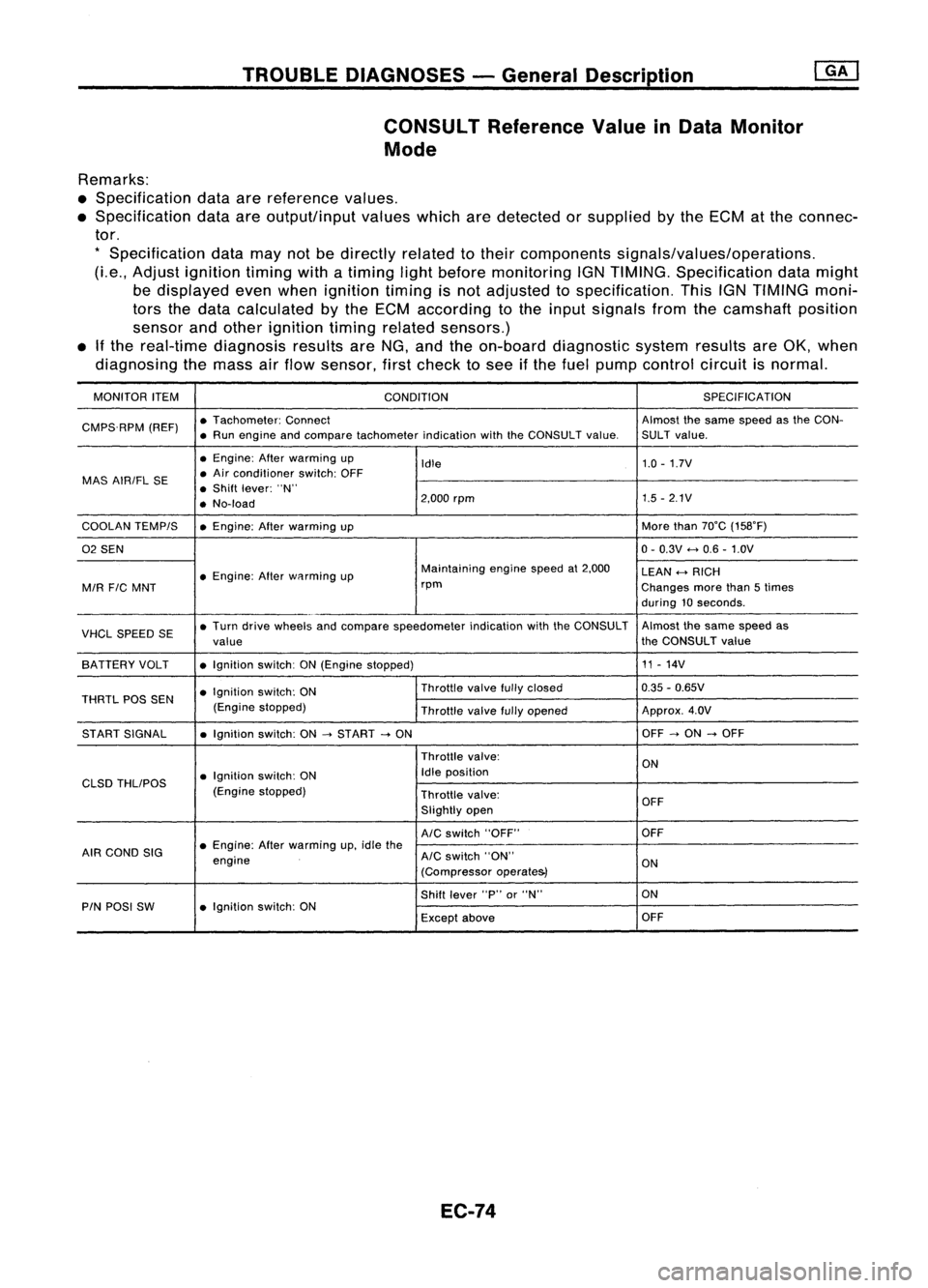
CONSULT ReferenceValueinData Monitor
Mode
Remarks:
• Specification dataarereference values.
• Specification dataareoutput/input valueswhicharedetected orsupplied bythe ECM atthe connec-
tor.
*
Specification datamaynotbedirectly relatedtotheir components signals/values/operations.
(Le., Adjust ignition timingwithatiming lightbefore monitoring IGNTIMING. Specification datamight
be displayed evenwhen ignition timingisnot adjusted tospecification. ThisIGNTIMING moni-
tors thedata calculated bythe ECM according tothe input signals fromthecamshaft position
sensor andother ignition timingrelated sensors.)
• Ifthe real-time diagnosis resultsareNG, and theon-board diagnostic systemresultsareOK, when
diagnosing themass airflow sensor, firstcheck tosee ifthe fuel pump control circuitisnormal.
MONITOR ITEM
CONDITION SPEC
IFICA TION
CMPS.RPM (REF)•
Tachometer: Connect Almostthesame speed asthe CON-
• Run engine andcompare tachometer indicationwiththeCONSULT value.SULT value.
• Engine: Afterwarming up
Idle 1.0
-1.7V
MAS AIRIFL SE •
Air conditioner switch:OFF
• Shift lever: "N"
• No-load 2,000
rpm 1.5
-2.1V
COOLAN TEMPIS •Engine: Afterwarming up More
than70°C (158°F)
02 SEN 0-
0.3V
<-+
0.6 -1.0V
• Engine: Afterwflrming up Maintaining
enginespeedat2,000
LEAN
<-+
RICH
MIR
FIC
MNT rpm
Changesmorethan5times
during 10seconds .
VHCL SPEED SE•
Turn drive wheels andcompare speedometer indicationwiththeCONSULT Almost
thesame speed as
value the
CONSULT value
SA TTERY VOLT •Ignition switch:ON(Engine stopped) 11
-14V
• Ignition switch:ON Throttle
valvefullyclosed 0.35
-0.65V
THRTL POSSEN
(Enginestopped)
Throttlevalvefullyopened Approx.
4.0V
ST ART SIGNAL •Ignition switch:ON
-->
START
-->
ON OFF
-->
ON
-->
OFF
Throttle valve:
ON
• Ignition switch:ON Idle
position
CLSD THLIPOS
(Enginestopped)
Throttlevalve:
OFF
Slightly open
AIC
switch "OFF" OFF
AIR COND SIG •
Engine: Afterwarming up,idle the
engine
AIC
switch "ON"
ON
(Compressor operate&)
Shift lever "P"or"N" ON
PIN POSI SW •Ignition switch:ON
Exceptabove OFF
EC-74
Page 810 of 1701
TROUBLEDIAGNOSIS FORPOWER SUPPLY ~
Main Power Supply andGround Circuit(Cont'd)
•
-!.OK
Go to
III
"CHECK
GROUND CIRCUIT" on
next page.
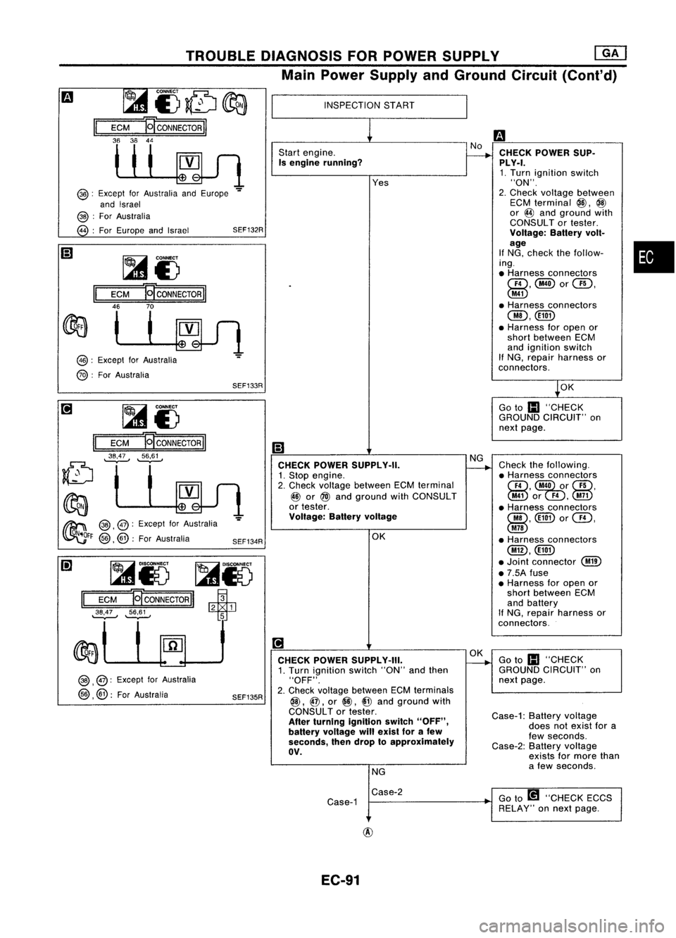
CHECK
POWER SUP-
PLY-I. 1. Turn ignition switch
"ON".
2. Check Yoltage between
ECM terminal
@,
@
or
@
and ground with
CONSULT ortester.
Voltage: Batteryvolt-
age
If NG, check thefollow-
ing .
• Harness connectors
GD,@orUD,
@
• Harness connectors
OO,@))
• Harness foropen or
short between ECM
and ignition switch
If NG, repair harness or
connectors.
Check thefollowing.
• Harness connectors
CID,
@O)ui)r
UD,
@or
F4,@
• Harness connectors
00, @))
or
Cill,
@
• Harness connectors
@,@))
• Joint connector
@
• 7.5A fuse
• Harness foropen or
short between ECM
and battery
If NG, repair harness or
connectors.
INSPECTION
START
Start engine.
Is engine running?
CHECK POWER SUPPLY-II.
1. Stop engine.
2. Check voltage between ECMterminal
~ or
@)
and ground withCONSULT
or tester.
Voltage: Batteryvoltage
OKYes
SEF134R
~i)
ECM
E[coNNECTORII
~;~~ ~i)
II
ECM
P!CONNECTORII
46 70
SEF133R
II
ECM
36 36
~85 ~r5
II
ECM
EJ
CONNECTOR
II
~53 1
~'.S~ ~
@:
Except forAustralia andEurope
-=
and Israel
@ :
For Australia
@ :
For Europe andIsrael SEF132R
@:
Except forAustralia
@ :
For Australia
~ @,@:
Except forAustralia
~FF
@,
@:
ForAustralia
@ ,
@: Except forAustralia
@ ,@:
ForAustralia
SEF135R
[!]
CHECK POWER SUPPLY-III.
1. Turn ignition switch"ON"andthen
"OFF".
2. Check Yoltage between ECMterminals
@,
@,
or
@,
i@
and ground with
CONSULT ortester.
After turning ignition switch"OFF",
battery voltage willexist forafew
seconds, thendrop toapproximately
av.
NG ~
Goto
III
"CHECK
GROUND CIRCUIT" on
next page.
Case-1: Batteryvoltage
does notexist fora
few seconds.
Case-2: Batteryvoltage
exists formore than
a few seconds.
Case-2
Case-1 Go
to[!1 "CHECK ECCS
RELAY" onnext page.
EC-91
Page 826 of 1701
•
Voltage
V
Less than1.0
Conditions
Ignition switch"ON"(Engine stopped.)
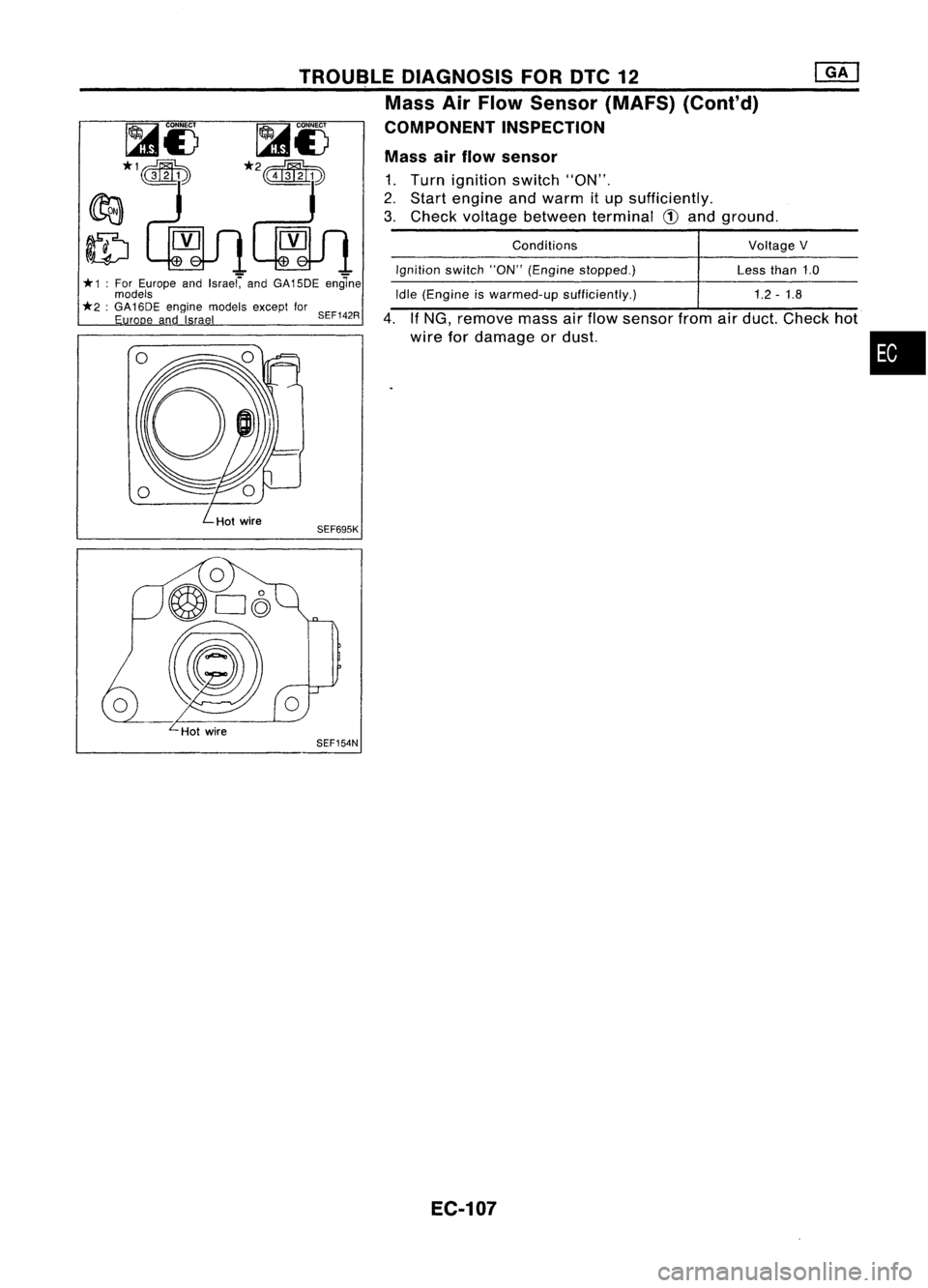
Mass
airflow sensor
1. Turn ignition switch"ON".
2. Start engine andwarm itup sufficiently.
3. Check voltage between terminal
CD
and ground.
Idle (Engine iswarmed-up sufficiently.) 1.2-1.8
4. IfNG, remove massairflow sensor fromairduct. Check hot
wire fordamage ordust.
TROUBLE
DIAGNOSIS FORDTC12
Mass AirFlow Sensor (MAFS) (Cont'd)
COMPONENT INSPECTION
- -
* 1:For Europe andIsrae( andGA15DE engine
models
*2 :GA 16DE engine models exceptfor
Euro eand Irael SEF142R
SEF154N
EC-107
Page 862 of 1701
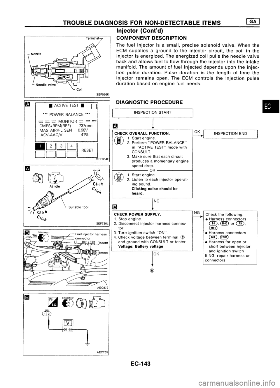
•
INSPECTION END
Check thefollowing.
• Harness connectors
@,@or@,
@
• Harness connectors
@,CillD
• Harness foropen or
short between injector
and ignition switch
If NG, repair harness or
connectors.
OK
NG
DIAGNOSTIC
PROCEDURE
INSPECTION START
CHECK OVERALL FUNCTION.
(F.I\
1.Start engine.
~ 2.Perform "POWER BALANCE"
in "ACTIVE TEST"modewith
CONSULT.
3. Make surethateach circuit
produces amomentary engine
speed drop.
OR
fff\
1.Start engine.
~ 2.Listen toeach injector operat-
ing sound.
Clicking noiseshould be
heard.
CHECK POWER SUPPLY.
1. Stop engine.
2. Disconnect injectorharness connec-
tor.
3. Turn ignition switch"ON".
4. Check voltage between terminal @
and ground withCONSULT ortester.
Voltage: Batteryvoltage
AEC872
SEF730L
/~~
Click
Ct.
'~.+
Fuel injector harness
connector
II
TROUBLE
DIAGNOSIS FORNON-DETECTABLE ITEMS
Injector (Cont'd)
COMPONENT DESCRIPTION
The fuel injector isasmall, precise solenoid valve.Whenthe
ECM supplies aground tothe injector circuit,thecoil
in
the
injector isenergized. Theenergized coilpulls theneedle valve
back andallows fueltoflow through theinjector intotheintake
manifold. Theamount offuel injected depends upontheinjec-
tion pulse duration. Pulseduration isthe length oftime the
injector remains open.TheECM controls theinjection pulse
duration basedonengine fuelneeds.
SEF596K
• ACTIVE TEST.
D
••• POWER BALANCE •••
= ==
MONITOR
=
==
CMPS.RPM(REF) 737rpm
MAS AIR/FL SEN098V
IACV-AAC/V 41%
110Q]Q]~
DDDDc:J
MEF354F
~7~
~ \)drJ
At idle
--
/ I
AEC755EC-143
Page 864 of 1701
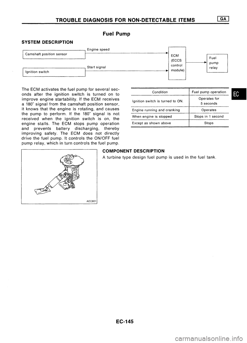
TROUBLEDIAGNOSIS FORNON-DETECTABLE ITEMS
Fuel Pump
SYSTEM DESCRIPTION
Enginespeed
Camshaft positionsensor
Startsignal
Ignition switch
The ECM activates thefuel pump forseveral sec-
onds aftertheignition switchisturned onto
improve enginestartability. Ifthe ECM receives
a 180
0
signal fromthecamshaft positionsensor,
it knows thattheengine isrotating, andcauses
the pump toperform. Ifthe 180
0
signal isnot
received whentheignition switchison, the
engine stalls.TheECM stops pump operation
and prevents batterydischarging, thereby
improving safety.TheECM does notdirectly
drive thefuel pump. Itcontrols theON/OFF fuel
pump relay, which inturn controls thefuel pump.
ECM
(ECCS
control module)
Condition
Ignition switchisturned toON.
Engine running andcranking
When engine isstopped
Except asshown above Fuel
pump relay
Fuel pump operation
Operates for
5 seconds
Operates
Stops in1second
Stops
•
COMPONENT DESCRIPTION
A turbine typedesign fuelpump isused inthe fuel tank.
AEC801
EC-145
Page 873 of 1701
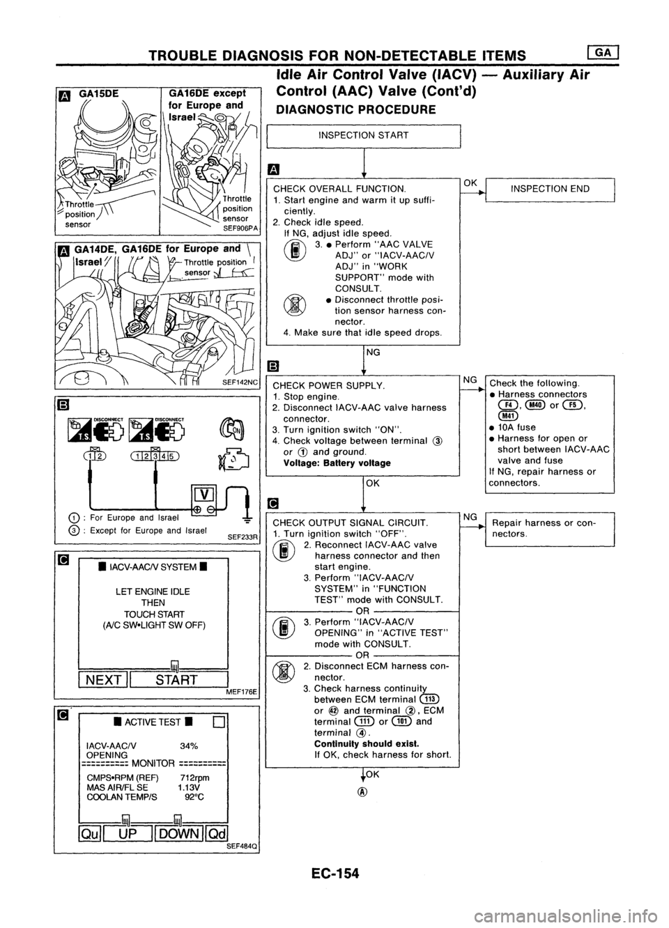
Repairharness orcon-
nectors. INSPECTION
END
Check thefollowing.
• Harness connectors
QD,@orQD,
@
• 10A fuse
• Harness foropen or
short between IACV-AAC
valve andfuse
If NG, repair harness or
connectors.
NG OK
NG
OK
INSPECTION
START
CHECK OVERALL FUNCTION.
1. Start engine andwarm itup suffi-
ciently.
2. Check idlespeed.
If NG, adjust idlespeed.
~ 3.• Perform "AACVALVE
~ ADJ"or"IACV-AACIV
ADJ" in"WORK
SUPPORT" modewith
CONSULT.
• Disconnect throttleposi-
tion sensor harness con-
nector.
4. Make surethatidlespeed drops.
OK
@
CHECK
POWER SUPPLY.
1. Stop engine.
2. Disconnect IACV-AACvalveharness
connector.
3. Turn ignition switch"ON".
4. Check voltage between terminal
@
or
G)
and ground.
Voltage: Batteryvoltage
CHECK OUTPUT SIGNALCIRCUIT.
1. Turn ignition switch"OFF".
(ij\
2.Reconnect IACV-AACvalve
~ harnessconnector andthen
start engine.
3. Perform "IACV-AACIV
SYSTEM" in"FUNCTION
TEST" modewithCONSULT.
OR
(F.I\
3.Perform "IACV-AACIV
~ OPENING" in"ACTIVE TEST"
mode withCONSULT.
OR
M
2.Disconnect ECMharness con-
~ nectar.
3. Check harness continuity
between ECMterminal
(ill)
or
@
and terminal
@,
ECM
terminal
GID
or
@
and
terminal
@.
Continuity shouldexist.
If
OK, check harness forshort.
SEF233R
SEF142NC
o
•
ACTIVE TEST.
LET
ENGINE IDLE
THEN
TOUCH START
(AiC
SW-UGHT SWOFF)
•
IACV-AACN SYSTEM.
I ACV-AACN 34%
OPENING
==========
MONITOR
==========
CMPS-RPM (REF)712rpm
MAS AIRIFL SE 1.13V
COOLAN TEMPtS 92°C
TROUBLE
DIAGNOSIS FORNON-DETECTABLE ITEMS
ffiJ
Idle AirControl Valve(IACV) -Auxiliary Air
Control (AAC)Valve(Cont'd)
DIAGNOSTIC PROCEDURE
!:::=====mul===
I
NEXT" START
I
MEF176E
CD
:
For Europe andIsrael
@ :
Except forEurope andIsrael
~
Ii)
~i5~i5
dfu
CillffuID
illU--illU
~[]fl[OOWN][Qill SEF484Q
EC-154
Page 881 of 1701
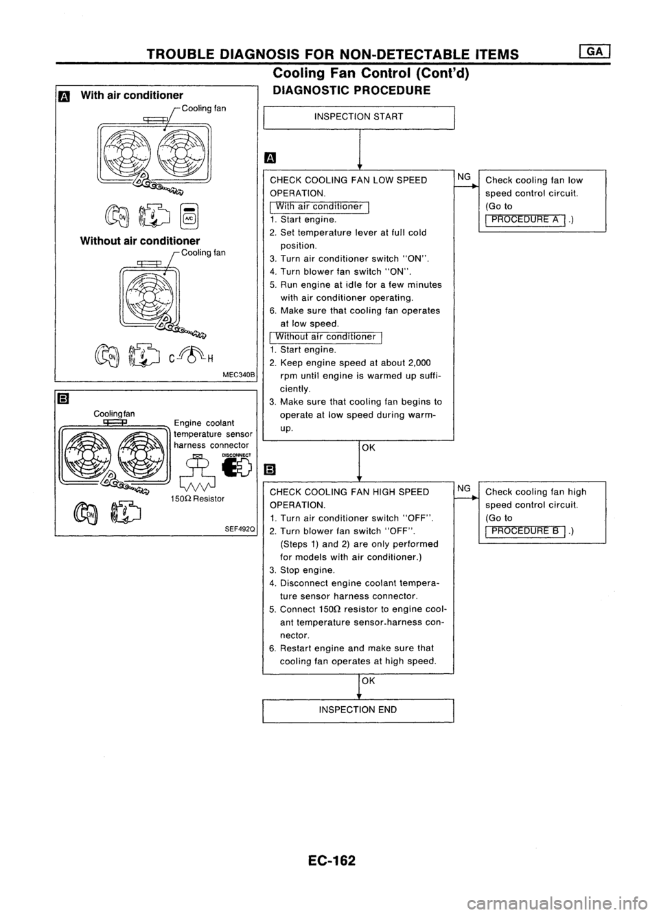
Checkcooling fanlow
speed control circuit.
(Go to
I
PROCEDURE A
I.)
Check cooling fanhigh
speed control circuit.
(Go to
I
PROCEDURE B
I.)
NG
NG
OK
INSPECTION
START
CHECK COOLING FANLOW SPEED
OPERATION.
I
With airconditioner
I
1. Start engine.
2. Set temperature leveratfull cold
position.
3. Turn airconditioner switch"ON".
4. Turn blower fanswitch "ON".
5. Run engine atidle forafew minutes
with airconditioner operating.
6. Make surethatcooling fanoperates
at low speed.
I
Without airconditioner
I
1. Start engine.
2. Keep engine speedatabout 2,000
rpm until engine iswarmed upsuffi-
ciently.
3. Make surethatcooling fanbegins to
operate atlow speed during warm-
up.
MEC340B
TROUBLE
DIAGNOSIS FORNON-DETECTABLE ITEMS
Cooling FanControl (Cant'd)
DIAGNOSTIC PROCEDURE
Cooling fan
Without
airconditioner
Coolingfan
Engine coolant
~ ~ ~a~~:;:t:a::;'~~'
~~ eN
lDoo
Q
CHECKCOOLING FANHIGH SPEED
150n
Resistor
~ ~ OPERATION.
~ ~ 1.Turn airconditioner switch"OFF".
SEF492Q
2.Turn blower fanswitch "OFF".
(Steps 1)and 2)are only performed
for models withairconditioner.)
3. Stop engine.
4. Disconnect enginecoolant tempera-
ture sensor harness connector.
5.
Connect
1500
resistor toengine cool-
ant temperature sensor.harness con-
nector.
6. Restart engineandmake surethat
cooling fanoperates athigh speed.
m
With airconditioner
Coolingfan
OK
INSPECTION END
EC-162