1995 NISSAN ALMERA N15 stop start
[x] Cancel search: stop startPage 976 of 1701
ON-BOARDDIAGNOSTIC SYSTEMDESCRIPTION
CONSULT (Cont'd)
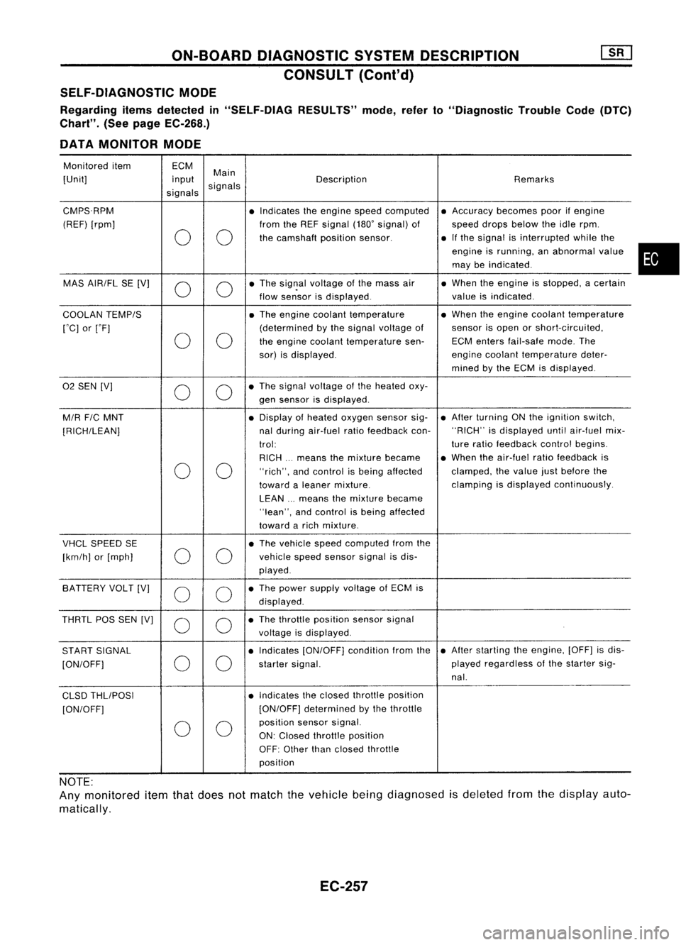
SELF-DIAGNOSTIC MODE
Regarding itemsdetected in"SELF-DiAG RESULTS"mode,referto"Diagnostic TroubleCode(DTC)
Chart". (Seepage EC-268.)
DATA MONITOR MODE
Monitored item ECM
Main
[Unit] input
signals Description
Remarks
signals
CMPS.RPM •Indicates theengine speedcomputed •
Accuracy becomespoorifengine
(REF) [rpm] fromtheREF signal (180'signal) of speeddropsbelow theidle rpm.
0 0
the
camshaft positionsensor. •
Ifthe signal isinterrupted whilethe
engine isrunning, anabnormal value
may beindicated .
MAS AIR/FL SE[V]
0 0
•
The sig~al voltage ofthe mass air •
When theengine isstopped, acertain
flow sensor isdisplayed. valueisindicated .
COOLAN TEMP/S •
The engine coolant temperature •
When theengine coolant temperature
rOC] orrF] (determined
bythe signal voltage ofsensor
isopen orshort-circuited,
0 0
the
engine coolant temperature sen-ECMenters fail-safe mode.The
sor) isdisplayed. engine
coolant temperature deter-
mined bythe ECM isdisplayed .
02
SEN [V]
00
•
The signal voltage ofthe heated oxy-
gen sensor isdisplayed.
M/R F/CMNT •
Display ofheated oxygen sensorsig-•
After turning ONthe ignition switch,
[RICH/LEAN] nal
during air-fuel ratiofeedback con-"RICH"
isdisplayed untilair-fuel mix-
trol: ture
ratio feedback controlbegins.
RICH ...means themixture became •
When theair-fuel ratiofeedback is
0 0
"rich",
andcontrol isbeing affected clamped,
thevalue justbefore the
toward aleaner mixture. clamping
isdisplayed continuously.
LEAN ...means themixture became
"lean", andcontrol isbeing affected
toward arich mixture .
VHCL SPEED SE •
The vehicle speedcomputed fromthe
[km/h] or[mph]
00
vehicle
speedsensor signalisdis-
played .
SA TTERY VOLT[V]
0 0
•
The power supply voltage ofECM is
displayed .
THRTL POSSEN [V]
0 0
•
The throttle position sensorsignal
voltage isdisplayed.
START SIGNAL •
Indicates [ON/OFF] conditionfromthe•
After starting theengine, [OFF]isdis-
[ON/OFF]
00
starter
signal. played
regardless ofthe starter sig-
nal.
CLSD THLIPOSI •
Indicates theclosed throttle position
[ON/OFF] [ON/OFF]
determined bythe throttle
0 0
position
sensorsignal.
ON: Closed throttle position
OFF: Other thanclosed throttle
position
NOTE:
Any monitored itemthatdoes notmatch thevehicle beingdiagnosed isdeleted fromthedisplay auto-
matically.
EC-257
•
Page 986 of 1701
TROUBLEDIAGNOSIS -General Description
KEY POINTS
WHAT .....
Vehicle &engine model
WHEN
Date,Frequencies
WHERE Roadconditions
HOW Operatingconditions,
Weather conditions,
Symptoms
SEF907L
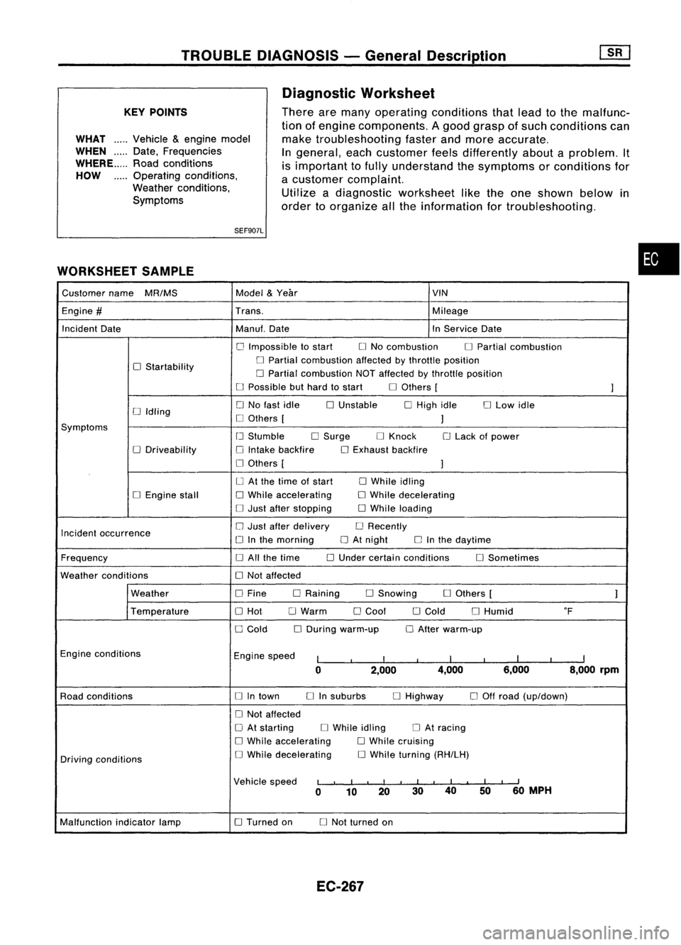
WORKSHEET SAMPLE Diagnostic
Worksheet
There aremany operating conditions thatlead tothe malfunc-
tion ofengine components. Agood grasp ofsuch conditions can
make troubleshooting fasterandmore accurate.
In
general, eachcustomer feelsdifferently aboutaproblem. It
is important tofully understand thesymptoms orconditions for
a customer complaint.
Utilize adiagnostic worksheet liketheone shown belowin
order toorganize allthe information fortroubleshooting.
•
Customer name
MR/MS Model
&
Year VIN
Engine
#
Trans. Mileage
Incident Date Manuf.Date InService Date
o
Impossible tostart
o
No combustion
o
Partial combustion
o
Startability
o
Partial combustion affectedbythrottle position
o
Partial combustion NOTaffected bythrottle position
o
Possible buthard tostart
o
Others [
]
o
No fast idle
o
Unstable
o
High idle
o
Low idle
[J
Idling
o
Others [
]
Symptoms
[J
Stumble
o
Surge
o
Knock
o
Lack ofpower
o
Driveability
o
Intake backfire
o
Exhaust backfire
o
Others [
]
o
At the time ofstart
o
While idling
o
Engine stall
o
While accelerating
o
While decelerating
o
Just after stopping
o
While loading
Incident occurrence
o
Just after delivery
o
Recently
o
Inthe morning
o
At night
o
Inthe daytime
Frequency
o
All the time
o
Under certain conditions
o
Sometimes
Weather conditions
o
Not affected
Weather
o
Fine DRaining
o
Snowing
o
Others [
]
Temperature
o
Hot
o
Warm
o
Cool
o
Cold
o
Humid
of
o
Cold
o
During warm-up
o
After warm-up
Engine conditions
Enginespeed
I
I
I
I
I
I
I
I
I
0 2,000 4,000
6,000 8,000rpm
Road conditions
o
Intown
o
Insuburbs
o
Highway
o
Off road (up/down)
o
Not affected
o
At starting
o
While idling
o
At racing
o
While accelerating
o
While cruising
Driving conditions
o
While decelerating
o
While turning (RH/LH)
Vehicle speed
I
I
I
I
I
I
II
I
I
I
II
0 10 20 3040
5060
MPH
Malfunction indicatorlamp
o
Turned on
o
Not turned on
EC-267
Page 990 of 1701
TROUBLEDIAGNOSIS -General Descrip_ti_on
1S_R_'
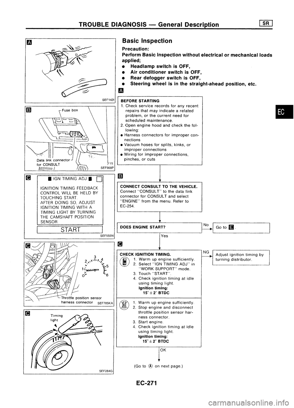
Basic Inspection
Precaution:
Perform BasicInspection withoutelectrical ormechanical loads
applied;
• Headlamp switchisOFF,
• Air conditioner switchisOFF,
• Rear defogger switchisOFF,
• Steering wheelisinthe straight-ahead position,etc.
m
BEFORE STARTING
1. Check service records forany recent •
repairs thatmay indicate arelated
problem, orthe current needfor
scheduled maintenance.
2. Open engine hoodandcheck thefol-
lowing:
• Harness connectors forimproper con-
nections
• Vacuum hosesforsplits, kinks,or
improper connections
• Wiring forimproper connections,
pinches, orcuts
Goto
(I.
No
CONNECT
CONSULTTOTHE VEHICLE.
Connect "CONSULT" tothe data link
connector forCONSULT andselect
"ENGINE" fromthemenu. Referto
EC-254.
DOES ENGINE START?
\\
~
~ SEF1421
START
•
IGN TIMING ADJ.
0
IGNITION TIMINGFEEDBACK
CONTROL WILLBEHELD BY
TOUCHING START
AFTER DOING SO,ADJUST
IGNITION TIMINGWITHA
TIMING LIGHTBYTURNING
THE CAMSHAFT POSITION
SENSOR.
SEF555N
Yes
CHECK IGNITION TIMING.
(ij\
1.Warm upengine sufficiently.
~ 2.Select "IGNTIMING ADJ"in
"WORK SUPPORT" mode.
3. Touch "START".
4. Check ignition timingatidle
using timing light.
Ignition timing:
15°::f:2° BTDC
~ 1Warm upengine sufficiently.
~ 2:
Stop engine anddisconnect
throttle position sensorhar-
ness connector.
3. Start engine.
4. Check ignition timingatidle
using timing light.
Ignition timing:
15°::f:2° BTDC
OK
(Go to
@
onnext page.) Adjust
ignition timingby
turning distributor.
EC-271
Page 996 of 1701
TROUBLEDIAGNOSIS -General Description
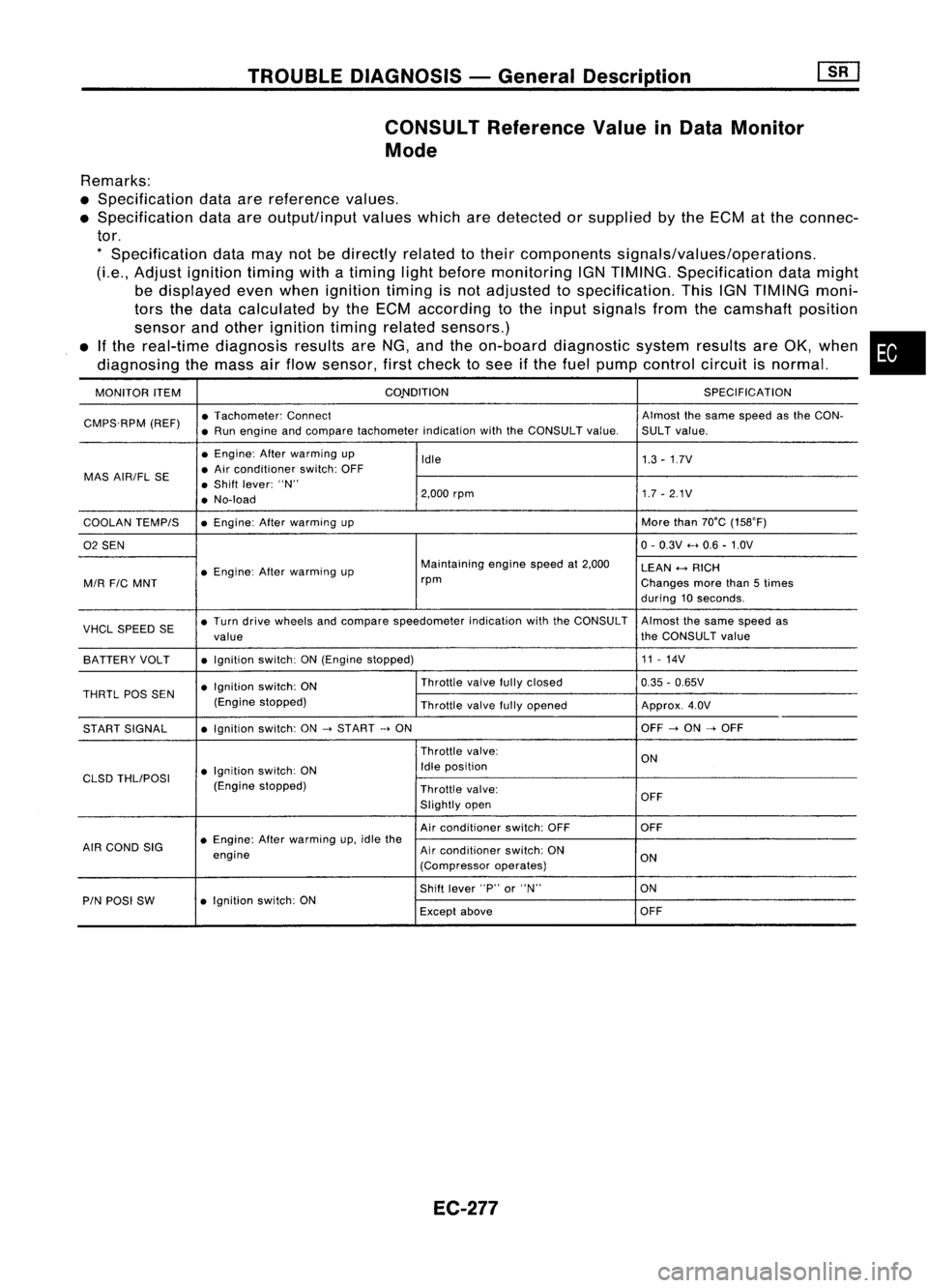
CONSULT Reference ValueinData Monitor
Mode
Remarks:
• Specification dataarereference values.
• Specification dataareoutput/input valueswhicharedetected orsupplied bythe ECM atthe connec-
tor.
*
Specification datamaynotbedirectly relatedtotheir components signals/values/operations.
(Le., Adjust ignition timingwithatiming lightbefore monitoring IGNTIMING. Specification datamight
be displayed evenwhen ignition timingisnot adjusted tospecification. ThisIGNTIMING moni-
tors thedata calculated bythe ECM according tothe input signals fromthecamshaft position
sensor andother ignition timingrelated sensors.)
• Ifthe real-time diagnosis resultsareNG, andtheon-board diagnostic systemresultsareOK, when •
diagnosing themass airflow sensor, firstcheck tosee ifthe fuel pump control circuitisnormal.
MONITOR ITEM CONDITION
SPECIFICATION
CMPS.RPM (REF)•
Tachometer: Connect Almostthesame speed asthe CON-
• Run engine andcompare tachometer indicationwiththeCONSULT value.SULTvalue.
• Engine: Afterwarming up
Idle 1.3-1.7V
MAS AIR/FL SE •
Air conditioner switch:OFF
• Shift lever: "N"
• No-load 2,000
rpm 1.7-2.1V
COOLAN TEMPIS •
Engine: Afterwarming up More
than70°C (15S0F)
02 SEN 0-
0.3V .....0.6 -1.0V
• Engine: Afterwarming up Maintaining
enginespeedat2,000
LEAN
+-->
RICH
MIR
FIC
MNT rpm
Changesmorethan5times
during 10seconds.
VHCL SPEED SE•
Turn drive wheels andcompare speedometer indicationwiththeCONSULT Almostthesame speed as
value the
CONSULT value
BATTERY VOLT •
Ignition switch:ON(Engine stopped) 11
-14V
• Ignition switch:ON Throttle
valvefullyclosed
0.35-0.65V
THRTL
pas
SEN
(Enginestopped)
Throttlevalvefullyopened Approx.4.0V
START SIGNAL •
Ignition switch:ON
->
START
->
ON OFF
->
ON
->
OFF
Throttle valve:
ON
• Ignition switch:ON Idle
position
CLSD THLIPOSI
(Enginestopped)
Throttlevalve:
Slightly open OFF
Air conditioner switch:OFF OFF
AIR COND SIG •
Engine: Afterwarming up,idle the
engine Air
conditioner switch:ON
ON
(Compressor operates)
Shift lever "P"or"N" ON
PIN POSI SW •
Ignition switch:ON
Exceptabove OFF
EC-277
Page 1006 of 1701
![NISSAN ALMERA N15 1995 Service Manual TROUBLEDIAGNOSIS FORPOWER SUPPLY
[]K]
Main Power Supply andGround Circuit(Cont'd)
II Il
~i)
ECM
Er
CONNECTOR
II
36
~i)
ECM
EfCONNECTORI!
~$
Lwt
INSPECTION
START
Start engine.
Is engin NISSAN ALMERA N15 1995 Service Manual TROUBLEDIAGNOSIS FORPOWER SUPPLY
[]K]
Main Power Supply andGround Circuit(Cont'd)
II Il
~i)
ECM
Er
CONNECTOR
II
36
~i)
ECM
EfCONNECTORI!
~$
Lwt
INSPECTION
START
Start engine.
Is engin](/manual-img/5/57349/w960_57349-1005.png)
TROUBLEDIAGNOSIS FORPOWER SUPPLY
[]K]
Main Power Supply andGround Circuit(Cont'd)
II Il
~i)
ECM
Er
CONNECTOR
II
36
~i)
ECM
EfCONNECTORI!
~$
Lwt
INSPECTION
START
Start engine.
Is engine running?
Yes
MEC746B
No
--+
CHECK
POWER SUP-
PL V-I.
1. Turn ignition switch
"ON".
2. Check voltage between
ECM terminal @and
ground withCONSULT
or tester.
Voltage: Batteryvolt-
age
If NG, check thefollow-
ing .
• Harness connectors
@,@
• Harness connectors
OO,@l)
• Harness foropen or
short between ECM
and ignition switch
If NG, repair harness or
connectors.
•
MEC714B
~OK
Go to
III
"CHECK
GROUND CIRCUIT" on
next page.
Check thefollowing.
• Harness connectors
@,@
• Harness connectors
OO,@l)
• 7.5A fuse
• Harness foropen or
short between ECM
and battery
If NG, repair harness or
connectors.
Case-1: Batteryvoltage
does notexist.
Case-2: Batteryvoltage
exists formore than
a few seconds.
OK
--+
Goto
III
"CHECK
GROUND CIRCUIT" on
next page.
NG
--+
CHECK POWER SUPPLV-III.
1. Turn ignition switch"ON"andthen
"OFF".
2. Check voltage between ECMterminals
@,
@
and ground withCONSULT
or tester.
Voltage:
After turning ignition switch"OFF",
battery voltage willexist forafew
seconds, thendrop toapproximately
QV.
CHECK
POWER SUPPLV.II.
1. Stop engine.
2. Check voltage between ECMterminals
@l ,
(ill)
andground withCONSULT
or tester.
Voltage: Batteryvoltage
MEC747BI OK
MEC748B
~
CONNECTOR
II
38' 47
"--.--'
ECM
Il
@
NG
Case-2
Case-1 Go
to
[it
"CHECK ECCS
RELA Y"onnext page.
EC-287
Page 1015 of 1701
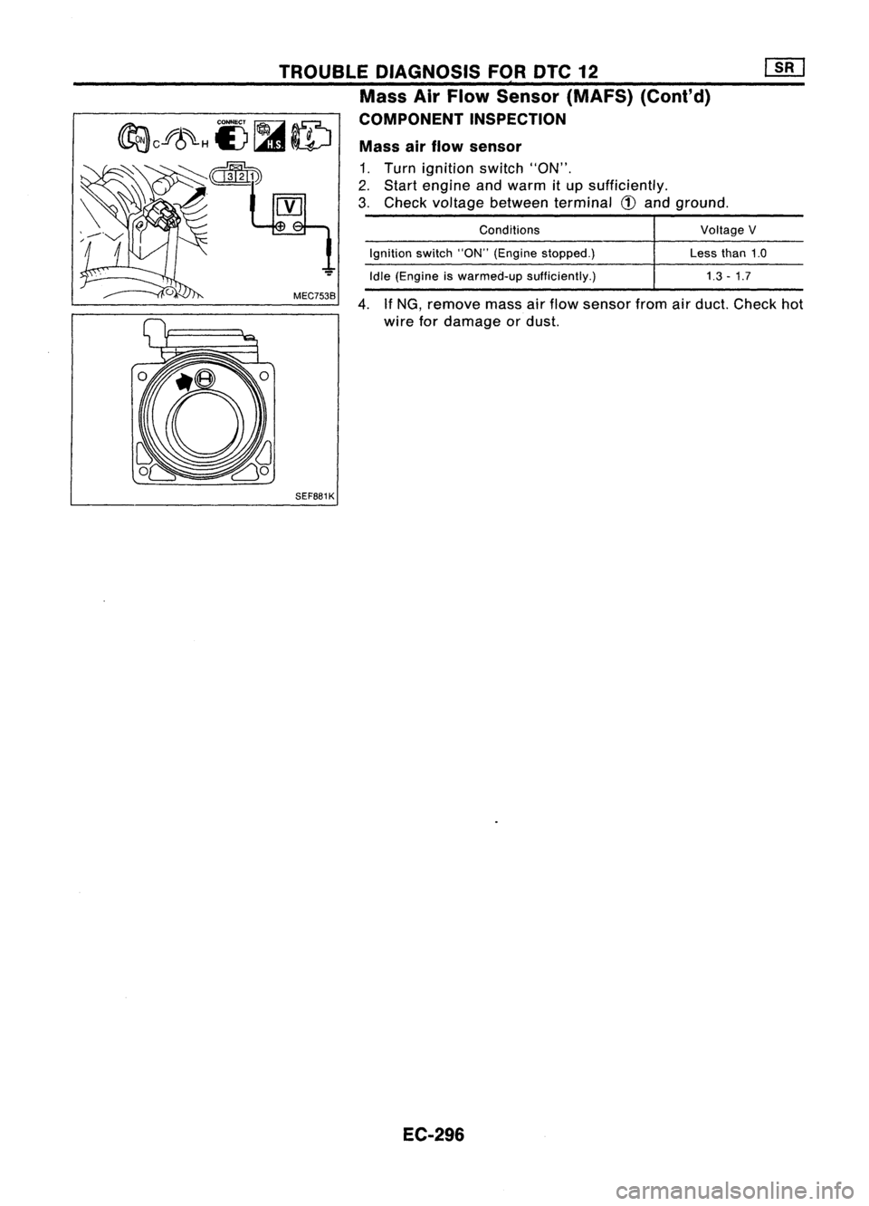
VoltageV
Less than1.0
1.3 -1.7
Conditions
Ignition switch"ON"(Engine stopped.)
Idle (Engine iswarmed-up sufficiently.)
4,
IfNG,
remove massairflow sensor fromairduct. Check hot
wire fordamage ordust.
Mass
airflow sensor
1, Turn ignition switch"ON",
2, Start engine andwarm itup sufficiently,
3, Check voltage between terminal
CD
and ground,
MEC753B
TROUBLE
DIAGNOSIS FORDTC12
,
Mass AirFlow Sensor (MAFS) (Cont'd)
COMPONENT INSPECTION
SEF881K
EC-296
Page 1044 of 1701
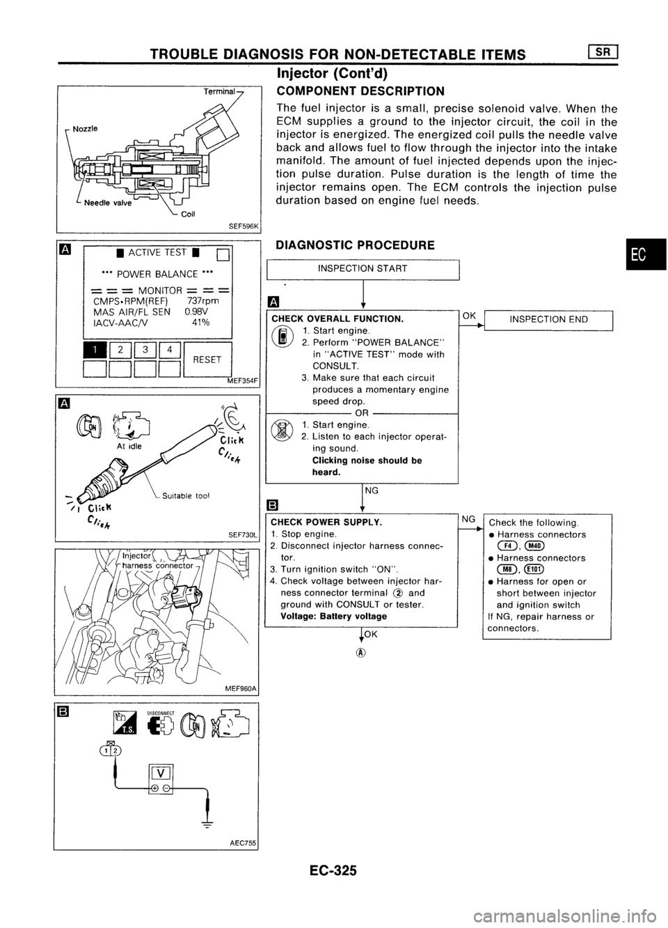
•
INSPECTION END
Check thefollowing.
• Harness connectors
@,@
• Harness connectors
@,
• Harness foropen or
short between injector
and ignition switch
If NG, repair harness or
connectors.
OK
NG
OK
@
INSPECTION
START
DIAGNOSTIC
PROCEDURE
CHECK OVERALL FUNCTION.
(ij\
1.Start engine.
~ 2.Perform "POWER BALANCE"
in "ACTIVE TEST"modewith
CONSULT.
3. Make surethateach circuit
produces amomentary engine
speed drop.
OR
~ 1.Start engine.
~ 2.Listen toeach injector operat-
ing sound.
Clicking noiseshould be
heard.
CHECK POWER SUPPLY.
SEF730L
1.Stop engine.
2. Disconnect injectorharness connec-
tor.
3. Turn ignition switch"ON".
4. Check voltage between injectorhar-
ness connector terminal
@
and
ground withCONSULT ortester.
Voltage: Batteryvoltage
SEF596K
I~~
Click
Ct.
I~-+
TROUBLE
DIAGNOSIS FORNON-DETECTABLE ITEMS
Injector
{Cont'd)
COMPONENT DESCRIPTION
The fuel injector isasmall, precise solenoid valve.Whenthe
ECM supplies aground tothe injector circuit,thecoil inthe
injector isenergized. Theenergized coilpulls theneedle valve
back andallows fueltoflow through theinjector intotheintake
manifold. Theamount offuel injected depends upontheinjec-
tion pulse duration. Pulseduration isthe length oftime the
injector remains open.TheECM controls theinjection pulse
duration basedonengine fuelneeds.
• ACTIVE TEST.
0
••• POWER BALANCE •••
= ==
MONITOR
=
=
=
CMPS.RPM(REF) 737rpm
MAS AIR/FL SENO.98V
IACV-AACjV 41%
110Q]~~
DDDDL:::J
MEF354F
--
/1
MEF960AAEC755 EC-325
Page 1046 of 1701
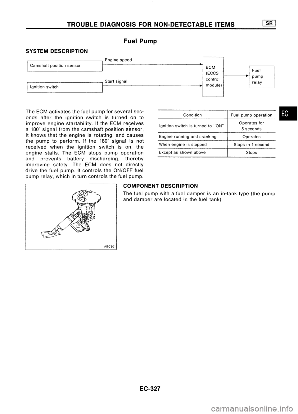
TROUBLEDIAGNOSIS FORNON-DETECTABLE ITEMS
Fuel Pump
SYSTEM DESCRIPTION
I
Camshaft positionsensor
I
Engine speed
~
ECM
(ECCS Fuel
control pump
!,gnition switch Start
signal
relay
I
module)
The ECM activates thefuel pump forseveral sec-
onds aftertheignition switchisturned onto
improve enginestartability. Ifthe ECM receives
a 180
0
signal fromthecamshaft positionsensor,
it knows thattheengine isrotating, andcauses
the pump toperform. Ifthe 180
0
signal isnot
received whentheignition switchison, the
engine stalls.TheECM stops pump operation
and prevents batterydischarging, thereby
improving safety.TheECM does notdirectly
drive thefuel pump. Itcontrols theON/OFF fuel
pump relay,which inturn controls thefuel pump.
Condition
Ignition switchisturned to"ON"
Engine running andcranking
When engine isstopped
Except asshown above Fuel
pump operation •
Operates for
5 seconds
Operates
Stops in1second
Stops
COMPONENT DESCRIPTION
The fuel pump withafuel damper isan in-tank type(thepump
and damper arelocated inthe fuel tank).
AECB01
EC-327