1995 NISSAN ALMERA N15 stop start
[x] Cancel search: stop startPage 921 of 1701
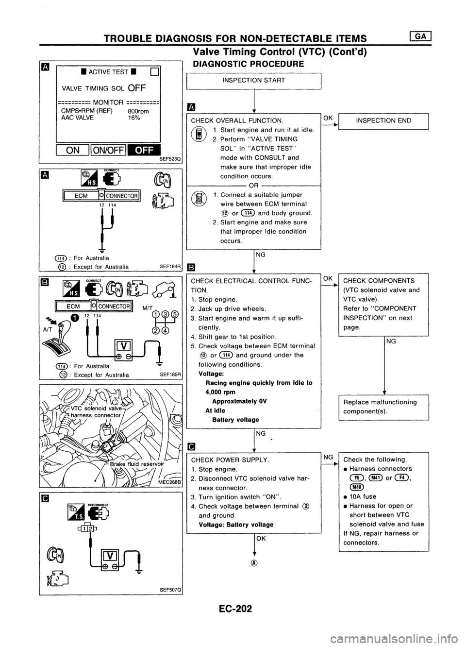
TROUBLEDIAGNOSIS FORNON-DETECTABLE ITEMS
Valve Timing Control (VTC)(Cant'd)
DIAGNOSTIC PROCEDURE
INSPECTION START
m
CHECK OVERALL FUNCTION.
~
INSPECTION
END
00
1.
Start engine andrunitat idle.
2. Perform "VALVETIMING
SOL" in"ACTIVE TEST"
mode withCONSULT and
make surethatimproper idle
condition occurs.
OR
00
1.
Connect asuitable jumper
wire between ECMterminal
@
or
@
andbody ground.
2. Start engine andmake sure
that improper idlecondition
occurs.
NG
iii
CHECK ELECTRICAL CONTROLFUNC-OK
CHECK COMPONENTS
TION.
-+
(VTCsolenoid valveand
1. Stop engine. VTC
valve).
2. Jack updrive wheels. Refer
to"COMPONENT
3. Start engine andwarm itup suffi- INSPECTION"
onnext
ciently. page.
4. Shift gearto1st position.
NG
5. Check voltage between ECMterminal
@
or
@
andground underthe
following conditions.
Voltage: Racing engine quickly fromidleto
4,000 rpm
Approximately OV
Replacemalfunctioning
At idle
component(s).
Battery voltage
NG
.
[!J
CHECK POWER SUPPLY. NG
Check thefollowing.
1. Stop engine.
~
•Harness connectors
2. Disconnect VTCsolenoid valvehar- QD,@or@,
ness connector.
@
3. Turn ignition switch"ON". •
10A fuse
4. Check voltage between terminal
@
•
Harness foropen or
and ground. short
between VTC
Voltage: Batteryvoltage
solenoid
valveandfuse
OK If
NG, repair harness or
connectors.
SEF185R
SEF507Q
SEF184R
M/T
~r5 ~
~£)
II
ECM
~CONNECTORII
12 114
~
ON
II
ON/OFF
IEDI
SEF523Q
•
ACTIVE TEST.
0
VALVE TIMING SOL
OFF
==========
MONITOR
==========
CMPS.RPM (REF)800rpm
AAC VALVE 16%
@):
ForAustralia
@:
Except forAustralia
@):
ForAustralia
12 :Except forAustralia
~i)~ID~
II
ECM
NCONNECTORII
A~fl "'"
~
EC-202
Page 927 of 1701
Referto"TROUBLE
DIAGNOSES" inHA sec-
tion.
Check thefollowing.
• Harness connectors
QD,@
• Harness connectors
@,@
• Harness foropen or
short between IACV-
AAC valve orIACV-
FICO solenoid valve
harness connector and
air conditioner relay
If NG, repair harness or
connectors.
O~L.-
__I_N_S_P_E_CT_I_O_N_E_N_D __
NG
NG
NG
INSPECTION
START
DIAGNOSTIC
PROCEDURE
Check ifair conditioner compressor
functions normally.
OK
OK
CHECK
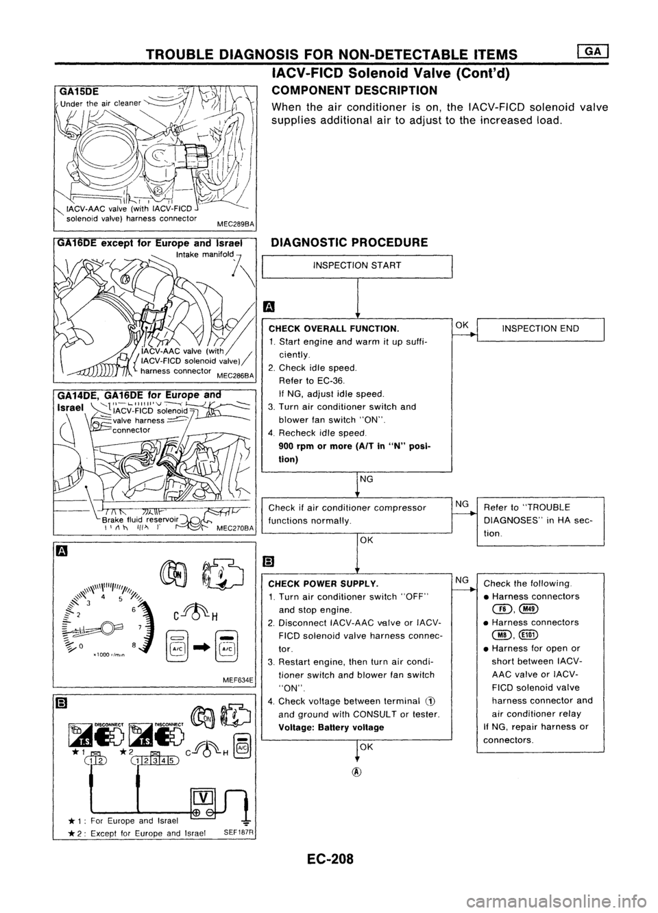
POWER SUPPLY.
1. Turn airconditioner switch"OFF"
and stop engine.
2. Disconnect IACV-AACvalveorIACV-
FICO solenoid valveharness connec-
tor.
3. Restart engine, thenturnaircondi-
tioner switch andblower fanswitch
"ON".
4. Check voltage between terminal
(1)
and ground withCONSULTor tester.
Voltage: Batteryvoltage
SEF187R
MEC289BA
MEF634E
TROUBLE
DIAGNOSIS FORNON-DETECTABLE ITEMS
IACV-FICD SolenoidValve(Cont'd)
COMPONENT DESCRIPTION
When theairconditioner ison, the IACV-FICD solenoidvalve
supplies additional airtoadjust tothe increased load.
~n
* 1: For Europe andIsrael ~
t
* 2: Except forEurope andIsrael
GA14DE,
GA16DEforEurope an
Israel
~'IACV_FIICI~'~O~~'d~
(\ ~valve harness~
~ connector
/
GA
6DE except forEurope andIsrael
'""k,
mM,o"l \
~m
[' ~.CHECKOVERALL FUNCTION.
1. Start engine andwarm itup suffi-
{ iAcv-AAC valve(with / ciently.
IACV-FICD solenoidvalve)
harness connector MEC286BA 2.Check idlespeed.
Refer toEC-36.
If NG, adjust idlespeed.
3. Turn airconditioner switchand
blower fanswitch "ON".
4. Recheck idlespeed.
900 rpm ormore (AITin
"N"
posi-
tion)
EC-208
Page 953 of 1701
![NISSAN ALMERA N15 1995 Service Manual ENGINEANDEMISSION BASICCONTROL SYSTEMDESCRIPTION [][]
Multiport FuelInjection (MFI)System (Cont'd)
CLOSED LOOP MIXTURERATIOFEEDBACK CONTROL(CLOSEDLOOP
CONTROL CONTROL)
The mixture ratiofeedback s NISSAN ALMERA N15 1995 Service Manual ENGINEANDEMISSION BASICCONTROL SYSTEMDESCRIPTION [][]
Multiport FuelInjection (MFI)System (Cont'd)
CLOSED LOOP MIXTURERATIOFEEDBACK CONTROL(CLOSEDLOOP
CONTROL CONTROL)
The mixture ratiofeedback s](/manual-img/5/57349/w960_57349-952.png)
ENGINEANDEMISSION BASICCONTROL SYSTEMDESCRIPTION [][]
Multiport FuelInjection (MFI)System (Cont'd)
CLOSED LOOP MIXTURERATIOFEEDBACK CONTROL(CLOSEDLOOP
CONTROL CONTROL)
The mixture ratiofeedback systemprovides thebest air-fuel
Feedback signal
mixtureratiofordriveability andemission control.Thethree
way catalyst canthen better reduce CO,HCand NOx emissions.
This system usesaheated oxygen sensorinthe exhaust man-
ifold tomonitor ifthe engine operation isrich orlean. TheECM
adjusts theinjection pulsewidthaccording tothe sensor volt-
age signal. Formore information abouttheheated oxygen
sensor, refertoEC-362. Thismaintains themixture ratiowithin
MEF025DD
therange ofstoichiometric (idealair-fuel mixture).
This stage isreferred toas the closed loopcontrol condition.
OPEN LOOPCONTROL
The open loopsystem condition referstowhen theECM detects
any ofthe following conditions. Feedbackcontrolstopsinorder
to maintain stabilized fuelcombustion.
• Deceleration andacceleration
• High-load, high-speed operation
• Engine idling
• Malfunction ofheated oxygen sensororits circuit
• Insufficient activationofheated oxygen sensoratlow
engine coolant temperature
• High-engine coolanttemperature
• After shifting from"N"to"0"
• During warm-up
• When starting theengine
MIXTURE RATIOSELF-LEARNING CONTROL
The mixture ratiofeedback controlsystem monitors themixture
ratio signal transmitted fromtheheated oxygen sensor. This
feedback signalisthen senttothe ECM. TheECM controls the
basic mixture ratioasclose tothe theoretical mixtureratioas
possible. However, thebasic mixture ratioisnot necessarily con-
trolled asoriginally designed. Bothmanufacturing differences
(Le., mass airflow sensor hotwire) andcharacteristic changes
during operation (Le.,injector clogging) directlyaffectmixture
ratio.
Accordingly, thedifference betweenthebasic andtheoretical
mixture ratiosismonitored inthis system. Thisisthen com-
puted interms of"injection pulseduration" toautomatically
compensate forthe difference betweenthetwo ratios.
EC-234
Page 960 of 1701
~U5e
box
~~~
~11~1-
Datalinkconnector ~"
for CONSULT
t=====/
• FUEL PRESRELEASE. D
FUEL PUMP WillSTOP BY
TOUCHING STARTDURING
IDLE.
CRANK AFEW TIMES AFTER
ENGINE STALL
---S-T~-RT--
BASIC
SERVICE PROCEDURE
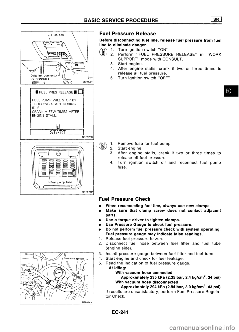
Fuel Pressure Release
Before disconnecting fuelline, release fuelpressure fromfuel
line toeliminate danger.
~ 1.Turn ignition switch"ON".
\J!I}
2.Perform "FUELPRESSURE RELEASE"in"WORK
SUPPORT" modewithCONSULT.
3. Start engine.
4. After engine stalls,crankittwo orthree times to
release allfuel pressure.
5. Turn ignition switch"OFF".
•
@ ~:
3.
SEF823K
SEF921P
SEF034K
Remove
fuseforfuel pump.
Start engine.
After engine stalls,crank
it
two orthree times to
release allfuel pressure.
4. Turn ignition switchoffand reconnect fuelpump
fuse.
Fuel Pressure Check
• When reconnecting fuelline, always usenew clamps.
• Make surethatclamp screwdoesnotcontact adjacent
parts.
• Use atorque drivertotighten clamps.
• Use Pressure Gaugetocheck fuelpressure.
• Donot perform fuelpressure checkwithsystem operating.
Fuel pressure gaugemayindicate falsereadings.
1. Release fuelpressure tozero.
2. Disconnect fuelhose between fuelfilter andfuel tube
(engine side).
3. Install pressure gaugebetween fuelfilter andfuel tube.
4. Start engine andcheck forfuel leakage.
5. Read theindication offuel pressure gauge.
At idling:
With vacuum hoseconnected
Approximately 235kPa (2.35 bar,2.4kg/cm
2,
34psi)
With vacuum hosedisconnected
Approximately 294kPa (2.94 bar,3.0kg/cm
2,
43psi)
If
results areunsatisfactory, performFuelPressure Regula-
tor Check.
EC-241
Page 961 of 1701
BASICSERVICE PROCEDURE
SEF310R
Vacuum
Fuelpressure
.... L
To
pressure regulator
SEF718B
'nsu'a,or~7
a-ring~1 ~
~> ~
InsUlalor~7
OJ'
Om~riJ$ _.
~lnjeCIOr
kJ
Insulator
11+-
1
~'I"
Localeplate
•. onthis side.
a-ring .
I
FuellUbe~i '.
assembly ,.
~'nsulator
I
SEF616N
MEC710B Fuel
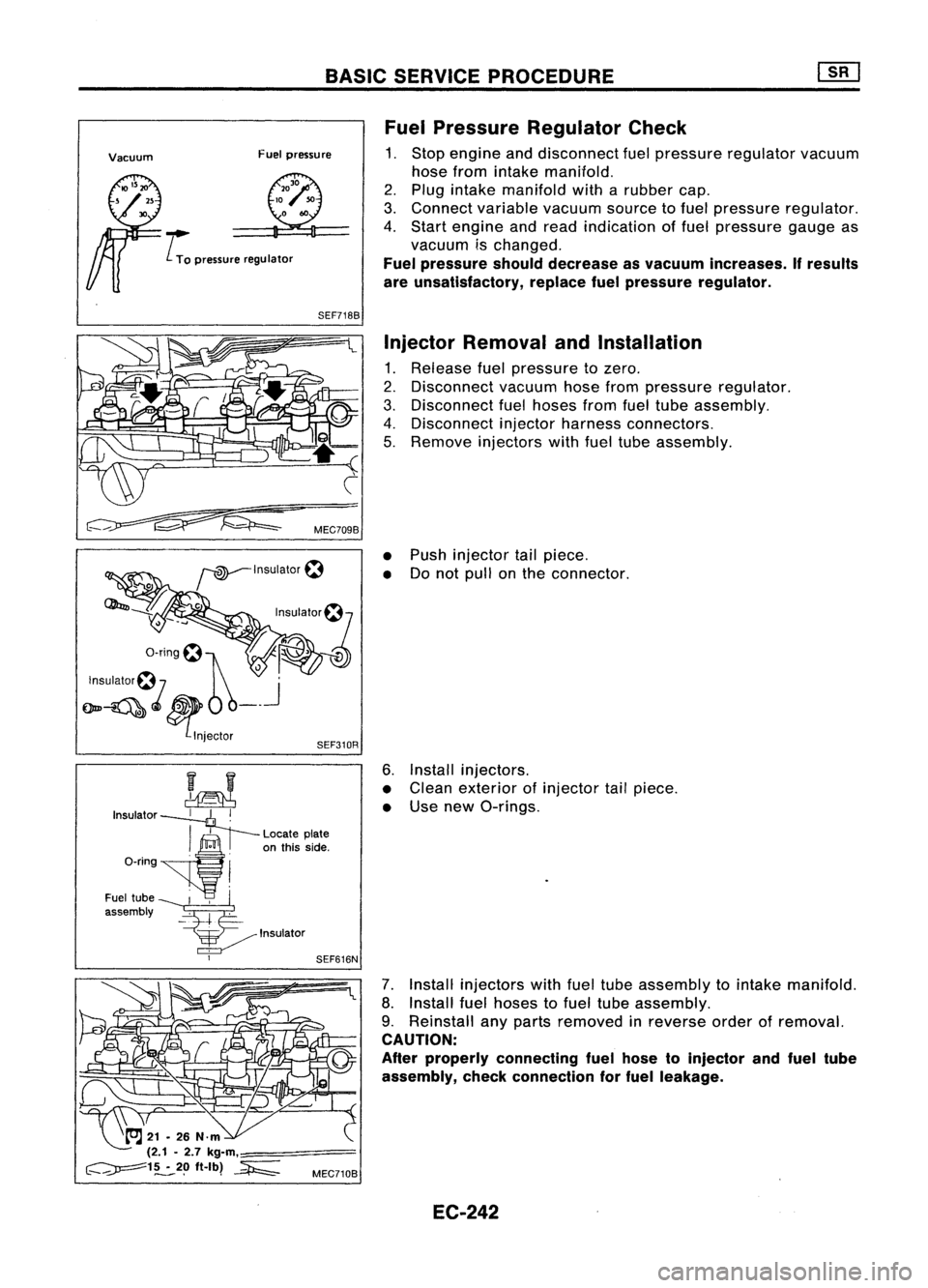
Pressure Regulator Check
1. Stop engine anddisconnect fuelpressure regulator vacuum
hose from intake manifold.
2. Plug intake manifold witharubber cap.
3. Connect variable vacuumsourcetofuel pressure regulator.
4. Start engine andread indication offuel pressure gaugeas
vacuum ischanged.
Fuel pressure shoulddecrease asvacuum increases. Ifresults
are unsatisfactory, replacefuelpressure regulator.
Injector Removal andInstallation
1. Release fuelpressure tozero.
2. Disconnect vacuumhosefrompressure regulator.
3. Disconnect fuelhoses fromfueltube assembly.
4. Disconnect injectorharness connectors.
5. Remove injectors withfueltube assembly.
• Push injector tailpiece.
• Donot pull onthe connector.
6. Install injectors.
• Clean exterior ofinjector tailpiece.
• Use new O-rings.
7. Install injectors withfueltube assembly tointake manifold.
8. Install fuelhoses tofuel tube assembly.
9. Reinstall anyparts removed inreverse orderofremoval.
CAUTION:
After properly connecting fuelhose toinjector andfuel tube
assembly, checkconnection forfuel leakage.
EC-242
Page 964 of 1701
AEC804
•
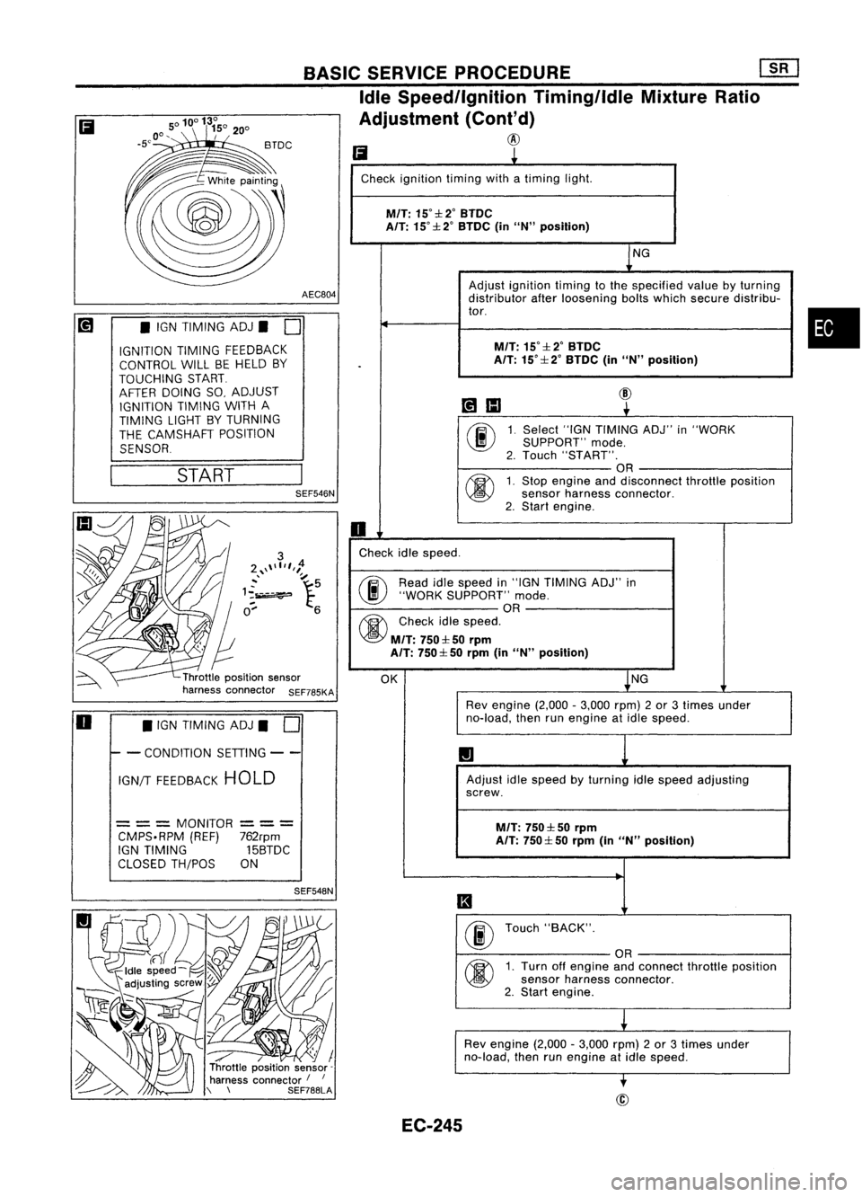
Ii
L
Check ignition timingwithatiming light.
M/T:
15°::l:2°BTDC
A/T: 15°::l: 2°BTDC (inUN" position)
NG
Adjust ignition timingtothe specified valuebyturning
distributor afterloosening boltswhich secure distribu-
tor.
M/T:
15°::l:2°BTDC
.
A/T:
15°::l: 2°BTDC (inUN" position)
~IIJ
@
~
00
1.
Select
"IGNTIMING ADJ"in"WORK
SUPPORT" mode.
2. Touch "START".
OR
@
1.
Stop engine anddisconnect throttleposition
sensor harness connector.
2. Start engine.
0
Check idlespeed.
@ Read
idlespeed in"IGN TIMING ADJ"in
"WORK SUPPORT" mode.
OR
@
Checkidlespeed.
M/T:
750::l: 50rprn
A/T: 750::l: 50rprn (inUN" position)
OK NG
Rev engine (2,000-3,000 rpm)2or 3times under
no-load, thenrunengine atidle speed.
1.1
Adjust idlespeed byturning idlespeed adjusting
screw.
M/T:
750::l: 50rpm
A/T: 750::l: 50rprn (inUN" position)
II
00
Touch
"BACK".
OR
@
1.
Turn offengine andconnect throttleposition
sensor harness connector.
2. Start engine.
L
Rev engine (2,000-3,000 rpm)2or 3times under
no-load, thenrunengine atidle speed.
-.
BASIC
SERVICE PROCEDURE
[]K]
Idle Speed/Ignition Timing/IdleMixtureRatio
Adjustment (Cont'd)
@
SEF548N
/ / I
Throttle position sensor-
harness connector /
I
\ \ SEF788LASEF546N
START
•
IGN TIMING ADJ.
0
IGNITION TIMINGFEEDBACK
CONTROL WILLBEHELD BY
TOUCHING START
AFTER DOING SO,ADJUST
IGNITION TIMINGWITHA
TIMING LIGHTBYTURNING
THE CAMSHAFT POSITION
SENSOR
= ==
MONITOR
==
=
CMPS.RPM (REF)762rpm
IGN TIMING 15BTDC
CLOSED TH/POS ON
Ii
o •
IGN TIMING ADJ.
0
I- -
CONDITION SETIING--
IGN/T FEEDBACK HOLD
EC-245
Page 969 of 1701
ON-BOARDDIAGNOSTIC SYSTEMDESCRIPTION
\ I/
'~/'
- CHECK-
/
.......
/ I\
SEF051P
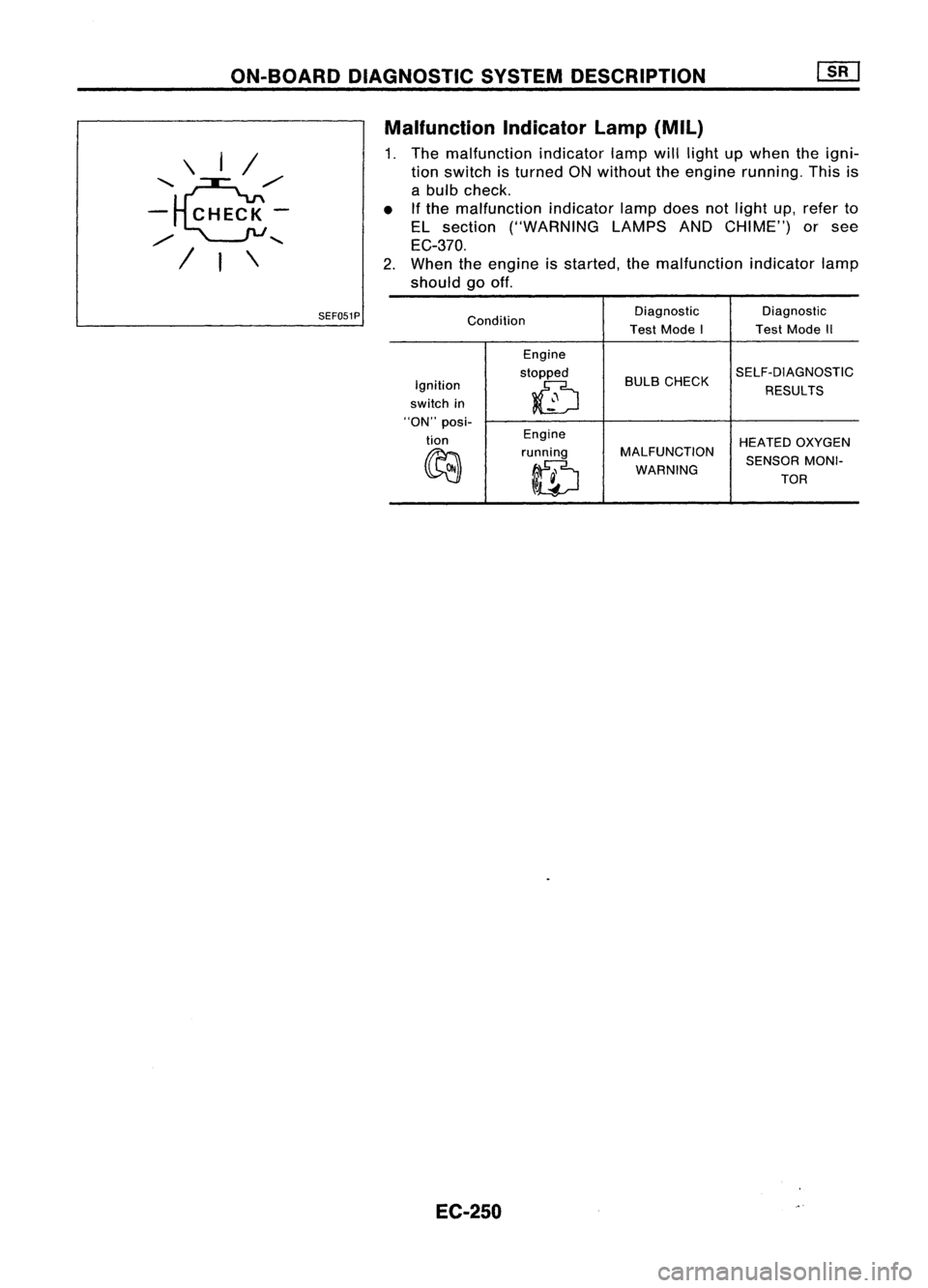
Malfunction
Indicatorlamp(Mil)
1. The malfunction indicatorlampwilllight upwhen theigni-
tion switch isturned ONwithout theengine running. Thisis
a bulb check.
• Ifthe malfunction indicatorlampdoes notlight up,refer to
EL section ("WARNING LAMPSANDCHIME") orsee
EC-370.
2. When theengine isstarted, themalfunction indicatorlamp
should gooff.
Condition Diagnostic
Diagnostic
Test Mode I TestMode II
Engine
stopped BULBCHECK SELF-DIAGNOSTIC
Ignition
0
RESULTS
switch in
"ON" posi-
tion Engine
HEATEDOXYGEN
~ running
MALFUNCTION
SENSORMONI-
ID
WARNING
TOR
EC-250
Page 975 of 1701
ON-BOARDDIAGNOSTIC SYSTEMDESCRIPTION
CONSULT (Cont'd)
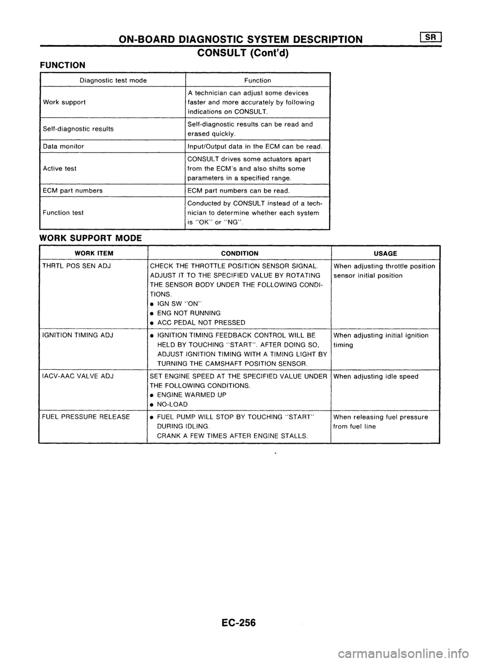
FUNCTION
Diagnostictestmode Function
A technician canadjust somedevices
Work support
fasterandmore accurately byfollowing
indications onCONSULT.
Self-diagnostic results Self-diagnostic
resultscanberead and
erased quickly.
Data monitor
Input/Outputdatainthe ECM canberead.
CONSULT drivessomeactuators apart
Active test fromtheECM's andalso shifts some
parameters inaspecified range.
ECM partnumbers
ECMpartnumbers canberead.
Conducted byCONSULT insteadofatech-
Function test
niciantodetermine whethereachsystem
is "OK" or"NG".
WORK SUPPORT MODE
WORK ITEM
CONDITION USAGE
THRTL POSSENADJ
CHECKTHETHROTTLE POSITIONSENSORSIGNAL. Whenadjusting throttleposition
ADJUST ITTO THE SPECIFIED VALUEBYROTATING
sensorinitialposition
THE SENSOR BODYUNDER THEFOLLOWING CONDI-
TIONS .
• IGN SW"ON"
• ENG NOTRUNNING
• ACC PEDAL NOTPRESSED
IGNITION TIMINGADJ
•IGNITION TIMINGFEEDBACK CONTROLWILLBE
Whenadjusting initialignition
HELD BYTOUCHING "START".AFTERDOINGSO, timing
ADJUST IGNITION TIMINGWITHATIMING LIGHTBY
TURNING THECAMSHAFT POSITIONSENSOR.
IACV-AAC VALVEADJ
SETENGINE SPEEDATTHE SPECIFIED VALUEUNDER
Whenadjusting idlespeed
THE FOLLOWING CONDITIONS.
• ENGINE WARMED UP
• NO-LOAD
FUEL PRESSURE RELEASE •FUEL PUMP WILLSTOP BYTOUCHING "START"
Whenreleasing fuelpressure
DURING IDLING.
fromfuelline
CRANK AFEW TIMES AFTER ENGINE STALLS
EC-256