1995 NISSAN ALMERA N15 stop start
[x] Cancel search: stop startPage 1087 of 1701
TROUBLEDIAGNOSIS FORNON-DETECTABLE ITEMS~
Torque Converter ClutchSolenoid Valve(Cont'd)
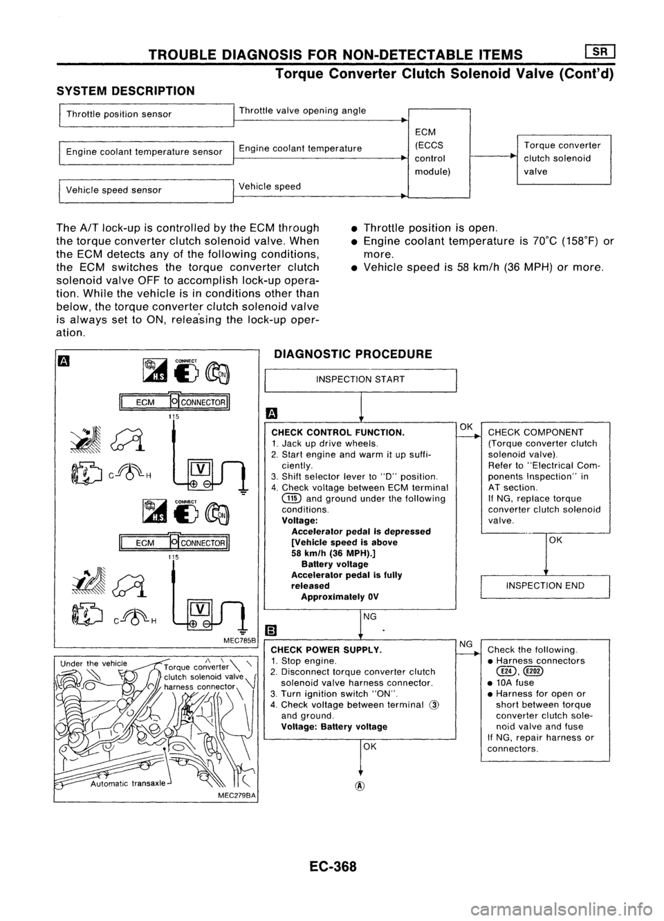
SYSTEM DESCRIPTION
Throttle position sensor Throttle
valveopening angle
Engine coolant temperature sensorEnginecoolant temperature ECM
(ECCS
control
module) Torque
converter
clutch solenoid
valve
Vehicle speedsensor Vehicle
speed
The
AfT
lock-up iscontrolled bythe ECM through
the torque converter clutchsolenoid valve.When
the ECM detects anyofthe following conditions,
the ECM switches thetorque converter clutch
solenoid valveOFFtoaccomplish lock-upopera-
tion. While thevehicle isinconditions otherthan
below, thetorque converter clutchsolenoid valve
is always settoON, relea'sing thelock-up oper-
ation. •
Throttle position isopen .
• Engine coolant temperature is70°C (158°F) or
more .
• Vehicle speedis58 kmfh (36MPH) ormore.
~i3~
II
ECM
E[CONNECTORII
DIAGNOSTIC
PROCEDURE
INSPECTION START
115
OK
INSPECTION END
CHECK
COMPONENT
(Torque converter clutch
solenoid valve).
Refer to"Electrical Com-
ponents Inspection" in
AT section.
If
NG, replace torque
converter clutchsolenoid
valve.
Check thefollowing.
• Harness connectors
@,
• 10A fuse
• Harness foropen or
short between torque
converter clutchsole-
noid valve andfuse
If NG, repair harness or
connectors.
NG
OK
OK
@
CHECK
CONTROL FUNCTION.
1. Jack updrive wheels.
2. Start engine andwarm itup suffi-
ciently.
3. Shift selector leverto"0" position.
4. Check voltage between ECMterminal
GID
andground underthefollowing
conditions.
Voltage: Accelerator pedalIsdepressed
[Vehicle speedisabove
58 km/h (36MPH).]
Battery voltage
Accelerator pedalisfully
released
Approximately OV
CHECK POWER SUPPLY.
1. Stop engine.
2. Disconnect torqueconverter clutch
solenoid valveharness connector.
3. Turn ignition switch"ON".
4. Check voltage between terminal
@
and ground.
Voltage: Batteryvoltage
-
MEC785B
MEC279BA
Ef
CONNECTOR
II
115
II
ECM
~~
ID
cf8~-H
EC-368
Page 1300 of 1701
SEM520DSEM515D TIMING
BELT
em
Camshaft TimingBelt(Cont'd)
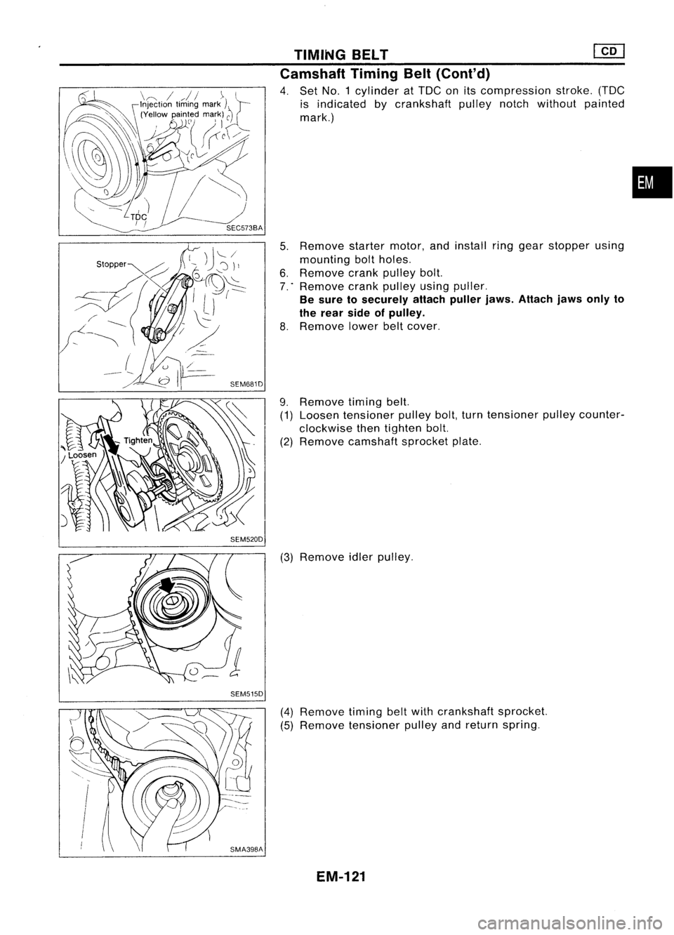
4. Set NO.1 cylinder atTDC onitscompression stroke.(TDC
is indicated bycrankshaft pulleynotchwithout painted
mark.)
5. Remove startermotor,andinstall ringgear stopper using
mounting boltholes.
6. Remove crankpulley bolt.
7 .. Remove crankpulley usingpuller.
Be sure tosecurely attachpullerjaws.Attach jawsonlyto
the rear sideofpulley.
8. Remove lowerbeltcover.
9. Remove timingbelt.
(1) Loosen tensioner pulleybolt,turntensioner pulleycounter-
clockwise thentighten bolt.
(2) Remove camshaft sprocketplate.
(3) Remove idlerpulley.
(4) Remove timingbeltwith crankshaft sprocket.
(5) Remove tensioner pulleyandreturn spring.
EM-121
•
Page 1371 of 1701
HOWTOREAD WIRING DIAGRAMS
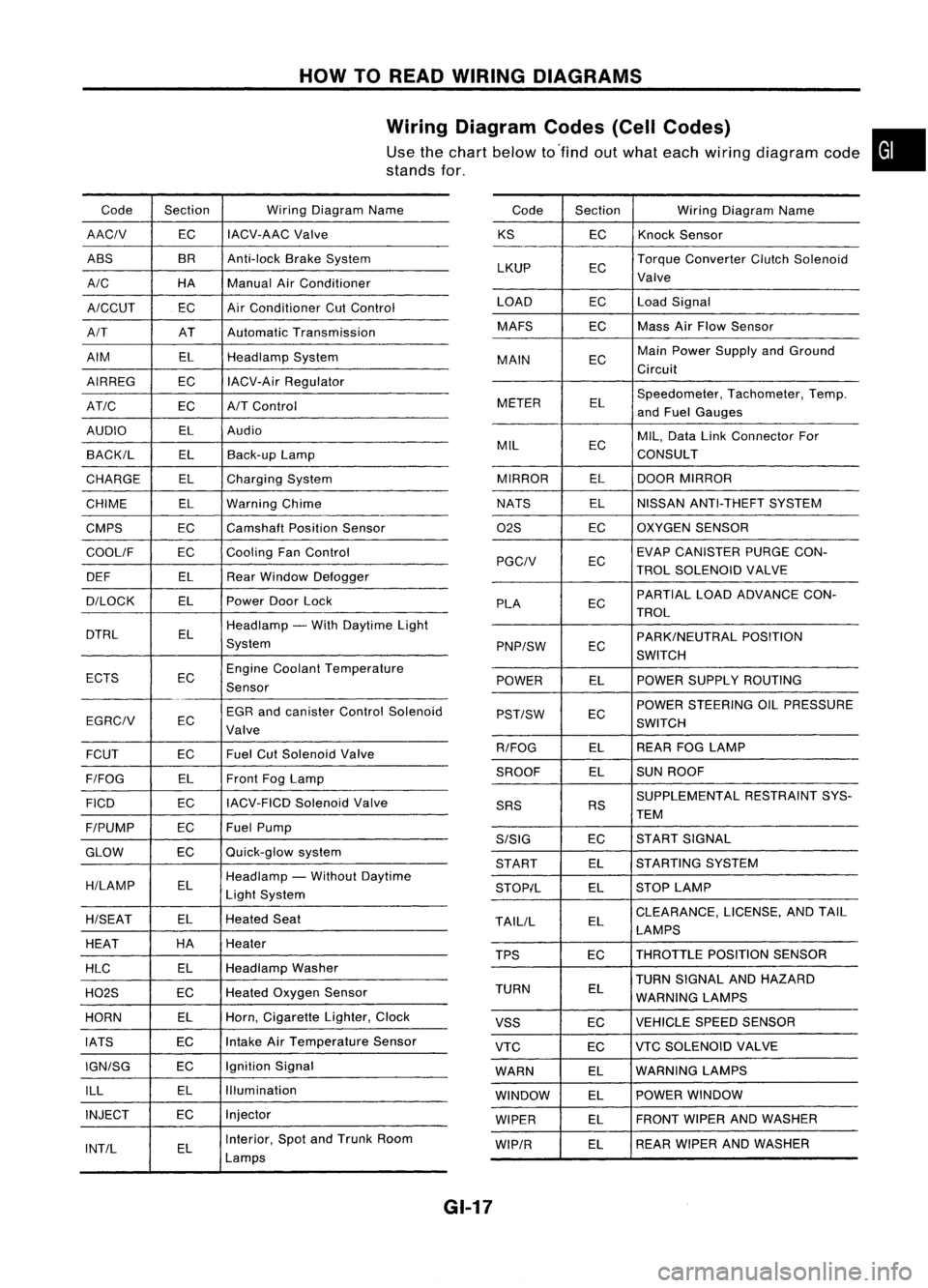
Wiring Diagram Codes(CellCodes)
Use thechart below to'find outwhat each wiring diagram code•
stands for,
Code Section WiringDiagram Name
AACIV ECIACV-AAC
Valve
ABS BR
Anti-lock BrakeSystem
A/C HAManualAirConditioner
A/CCUT ECAir
Conditioner CutControl
A/T ATAutomatic Transmission
AIM ELHeadlamp System
AIRREG ECIACV-Air Regulator
AT/C ECA/TControl
AUDIO ELAudio
BACK/L ELBack-up Lamp
CHARGE ELCharging System
CHIME ELWarning Chime
CMPS EC
Camshaft PositionSensor
COOllF ECCooling
FanControl
DEF ELRearWindow Defogger
D/LOCK ELPowerDoorLock
DTRL ELHeadlamp
-With Daytime Light
System
ECTS ECEngine
Coolant Temperature
Sensor
EGR andcanister ControlSolenoid
EGRCIV EC
Valve
FCUT ECFuel
CutSolenoid Valve
F/FOG ELFront
FogLamp
FICO ECIACV-FICD
SolenoidValve
F/PUMP ECFuel
Pump
GLOW ECQuick-glow
system
H/LAMP ELHeadlamp
-Without Daytime
Light System
H/SEAT ELHeated
Seat
HEAT HA
Heater
HLC ELHeadlamp
Washer
H02S ECHeated
Oxygen Sensor
HORN ELHorn,
Cigarette Lighter,Clock
IATS ECIntake
AirTemperature Sensor
IGN/SG ECIgnition
Signal
ILL ELIllumination
INJECT ECInjector
INT/L ELInterior,
SpotandTrunk Room
Lamps Code
Section WiringDiagram Name
KS ECKnock
Sensor
LKUP ECTorque
Converter ClutchSolenoid
Valve
LOAD ECLoadSignal
MAFS ECMass
AirFlow Sensor
MAIN ECMain
Power Supply andGround
Circuit
METER ELSpeedometer,
Tachometer,Temp.
and Fuel Gauges
MIL ECMIL,
Data LinkConnector For
CONSULT
MIRROR ELDOOR
MIRROR
NATS ELNISSAN
ANTI-THEFT SYSTEM
02S ECOXYGEN
SENSOR
EC EVAP
CANISTER PURGECON-
PGCIV TROLSOLENOID VALVE
PLA ECPARTIAL
LOADADVANCE CON-
TROL
EC PARK/NEUTRAL
POSITION
PNP/SW SWITCH
POWER ELPOWER
SUPPLY ROUTING
POWER STEERING OILPRESSURE
PST/SW EC
SWITCH
R/FOG ELREAR
FOGLAMP
SROOF ELSUN
ROOF
SUPPLEMENTAL RESTRAINTSYS-
SRS RS
TEM
S/SIG ECST
ART SIGNAL
START ELSTARTING
SYSTEM
STOP/L ELSTOP
LAMP
TAllIL ELCLEARANCE,
LICENSE,ANDTAIL
LAMPS
TPS ECTHROTTLE
POSITIONSENSOR
TURN SIGNAL ANDHAZARD
TURN EL
WARNING LAMPS
VSS ECVEHICLE
SPEEDSENSOR
VTC ECVTC
SOLENOID VALVE
WARN ELWARNING
LAMPS
WINDOW ELPOWER
WINDOW
WIPER ELFRONT
WIPERANDWASHER
WIP/R ELREAR
WIPER ANDWASHER
GI-17
Page 1385 of 1701
HOWTOFOLLOW FLOWCHART INTROUBLE DIAGNOSES
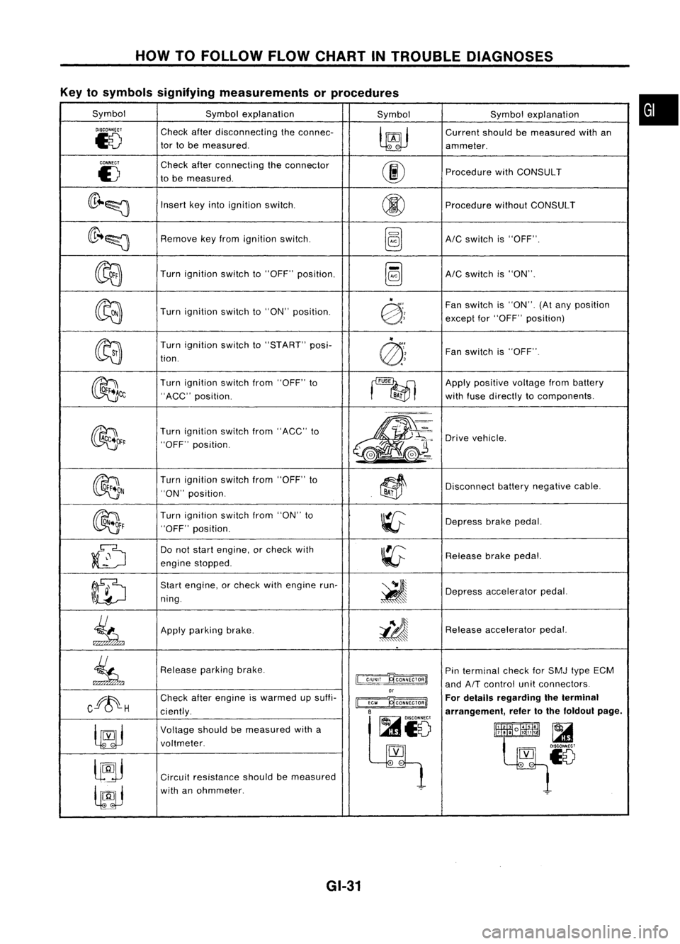
Key tosymbols signifying measurements orprocedures
Symbol Symbolexplanation
SymbolSymbolexplanation
DISCONNECT
Checkafterdisconnecting theconnec-
~
Current
shouldbemeasured withan
~8
tor
tobe measured.
ammeter.
CONNECT
Checkafterconnecting theconnector
00
E)
tobe measured. Procedure
withCONSULT
(lr~~
Insert
keyinto ignition switCh.
@
Procedure
withoutCONSULT
(lr ..~
Remove
keyfrom ignition switch.
~AIC
switch is"OFF".
~
Turn
ignition switchto"OFF" position.
~AIC
switch is"ON".
~
"
Fanswitch is"ON". (Atany position
Turn ignition switchto"ON" position.
@:;
exceptfor"OFF" position)
~ "
Turn ignition switchto"START" posi-
@'~
Fan
switch is"OFF".
tion.
~~
Turn
ignition switchfrom"OFF" to
~
Apply
positive voltagefrombattery
"ACC" position.
BA;
withfuse directly tocomponents.
~~r
Turn
ignition switchfrom"ACC" to
m-
~'~:
Drive
vehicle.
"OFF" position.
,.-=.
L
@J~ ..
~(e.-
OON
Turn
ignition switchfrom"OFF" to
~~
Disconnect
batterynegative cable.
"ON" position.
BAi
~F
Turn
ignition switchfrom"ON" to
~
Depress
brakepedal.
"OFF" position.
~
Do
not start engine, orcheck with
~
Release
brakepedal.
engine stopped.
ID
Start
engine, orcheck withengine run-
~
ning. Depress
accelerator pedal.
.
.
~
Apply
parking brake.
i!J
Release
accelerator pedal.
..
~
Release
parkingbrake.
~
Pin
terminal checkforSMJ typeECM
and
AIT
control unitconnectors
or
Cff~H
Check
afterengine iswarmed upsuffi-
~ For
details regarding theterminal
ciently.
B
arrangement,refertothe foldout page.
~io
~
Voltage
shouldbemeasured witha
lltlllliR~
t~~~18
voltmeter.
[YJ
lJ9j
.
-
Circuit resistance shouldbemeasured
lfJJ
with
anohmmeter.
~
GI-31
•
Page 1431 of 1701
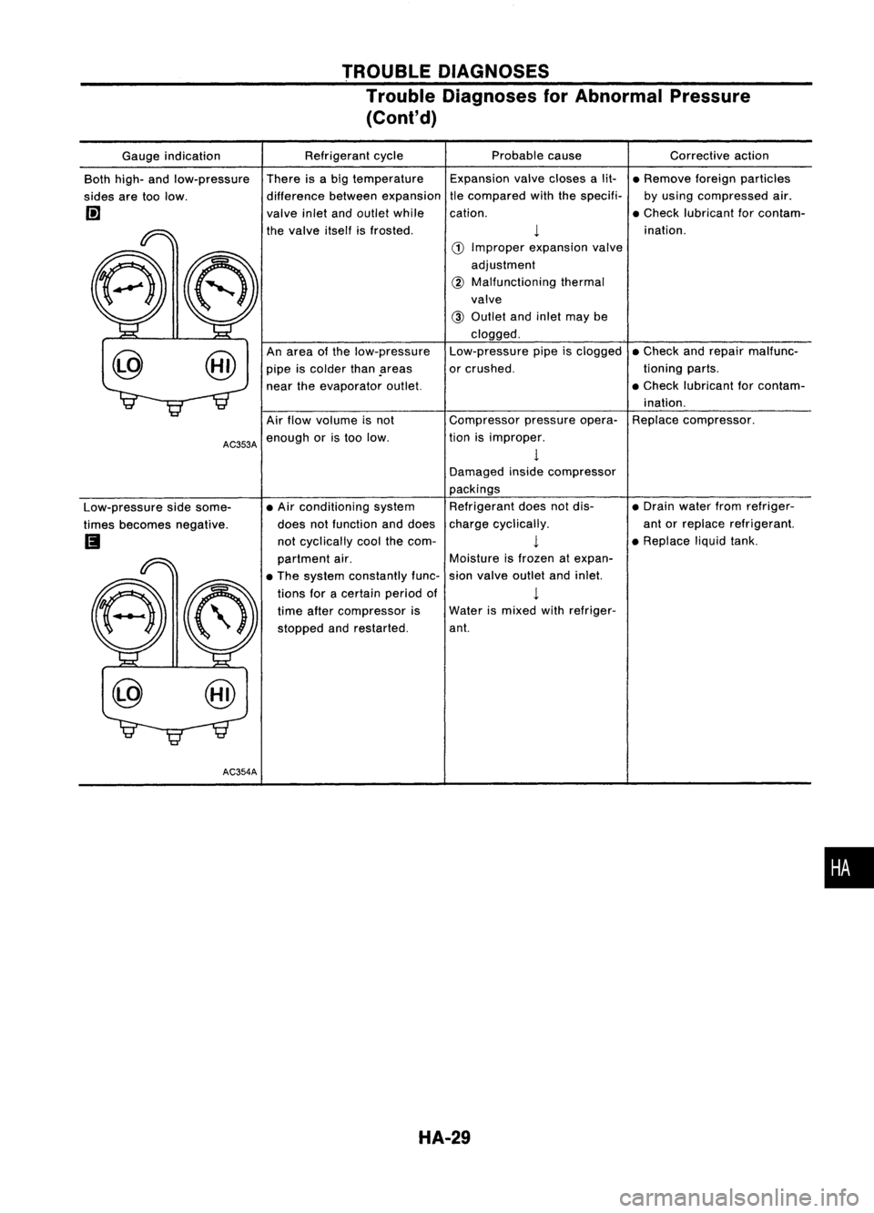
TROUBLEDIAGNOSES
Trouble Diagnoses forAbnormal Pressure
(Cont'd)
Correctiveaction
• Remove foreignparticles
by using compressed air.
• Check lubricant forcontam-
ination.
• Check andrepair malfunc-
tioning parts.
• Check lubricant forcontam-
ination.
Replace compressor.
• Drain water fromrefriger-
ant orreplace refrigerant.
• Replace liqUidtank.
Expansion
valvecloses alit-
tle compared withthespecifi-
cation.
1
Water ismixed withrefriger-
ant. Probable
cause
1
CD
Improper expansion valve
adjustment
@
Malfunctioning thermal
valve
@
Outlet andinlet maybe
clogged.
Low-pressure pipeisclogged
or crushed.
Compressor pressureopera-
tion isimproper.
1
Damaged insidecompressor
packings Refrigerant doesnotdis-
charge cyclically.
1
Moisture isfrozen atexpan-
sion valve outlet andinlet.
Refrigerant
cycle
There isabig temperature
difference betweenexpansion
valve inletandoutlet while
the valve itselfisfrosted.
An area ofthe low-pressure
pipe iscolder thanpreas
near theevaporator outlet.
• Air conditioning system
does notfunction anddoes
not cyclically coolthecom-
partment air.
• The system constantly func-
tions foracertain periodof
time after compressor is
stopped andrestarted.
Air
flow volume isnot
AC353A
enough oristoo low.
@ Gauge
indication
Both high- andlow-pressure
sides aretoolow.
l!]
Low-pressure sidesome-
times becomes negative.
Ii
AC354A
•
HA-29
Page 1467 of 1701
TROUBLEDIAGNOSES
Control Linkage Adjustment (Cont'd)
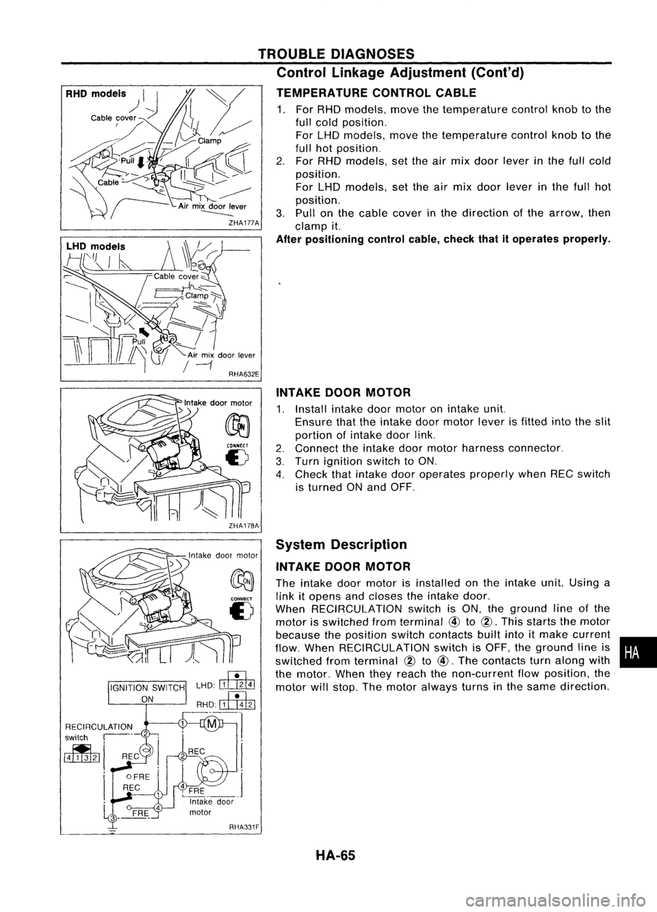
TEMPERATURE CONTROLCABLE
1. For RHO models, movethetemperature controlknobtothe
full cold position.
For LHO models, movethetemperature controlknobtothe
full hotposition.
2. For RHO models, setthe airmix door lever inthe fullcold
position.
For LHO models, setthe airmix door lever inthe full hot
position.
3. Pull onthe cable cover inthe direction ofthe arrow, then
clamp it.
After positioning controlcable,checkthatitoperates properly.
INTAKE DOORMOTOR
1. Install intakedoormotor onintake unit.
Ensure thattheintake doormotor leverisfitted intotheslit
portion ofintake doorlink.
2. Connect theintake doormotor harness connector.
3. Turn ignition switchtoON.
4. Check thatintake dooroperates properlywhenRECswitch
is turned ONand OFF.
ZHA178A
RHA331F System
Description
INTAKE DOORMOTOR
The intake doormotor isinstalled onthe intake unit.Using a
link itopens andcloses theintake door.
When RECIRCULATION switchisON, theground lineofthe
motor isswitched fromterminal
@
to
@.
This starts themotor
because theposition switchcontacts builtintoitmake current •
flow. When RECIRCULATION switchisOFF, theground lineis •
switched fromterminal
@
to
@.
The contacts turnalong with
the motor. Whentheyreach thenon-current flowposition, the
motor willstop. Themotor always turnsinthe same direction.
LHD:
u:Eh!.IJ
RHD:
o::EhhJ
---I
I
~----j Intake door
molar
HA-65
Page 1470 of 1701
SERVICEPROCEDURES
Maintenance ofLubricant Quantityin
Compressor
The lubricant inthe compressor circulatesthroughthesystem
with therefrigerant. Addlubricant tocompressor whenreplac-
ing any component orafter alarge gasleakage occurred. Itis
important tomaintain thespecified amount.
If lubricant quantityisnot maintained properly,thefollowing
malfunctions mayresult:
• Lack oflubricant: Maylead toaseized compressor
• Excessive lubricant:Inadequate cooling(thermal exchange
interference)
LUBRICANT
Name: Nissan
Ale
System OilType R
Part number:
KLHOO-PAGRO
CHECKING ANDADJUSTING
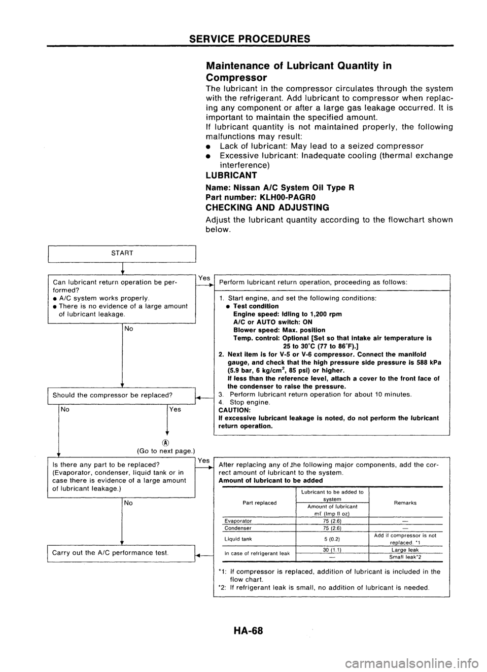
Adjust thelubricant quantityaccording tothe flowchart shown
below.
START
~
Can lubricant returnoperation beper- Yes
Perform lubricant returnoperation, proceeding asfollows:
formed?
-+
• AIC
system worksproperly. 1.Start engine, andsetthefollowing conditions:
• There isno evidence ofalarge amount •Test condition
of lubricant leakage. Engine
speed:Idlingto1,200 rpm
AlC orAUTO switch: ON
No Blowerspeed:Max.position
Temp. control: Optional [Setsothat Intake airtemperature is
25 to30°C (77to86°F).]
2. Next itemisfor V-5 orV-6 compressor. Connectthemanifold
gauge, andcheck thatthehigh pressure sidepressure is588 kPa
(5.9 bar, 6kg/cm
2,
85psi) orhigher,
If
less than thereference level,attach acover tothe front faceof
~
the
condenser toraise thepressure.
Should thecompressor bereplaced?
3.
Perform lubricant returnoperation forabout 10minutes.
4.
Stop engine.
No Yes
CAUTION:
If
excessive lubricantleakageisnoted, donot perform thelubricant
return operation.
@
(Go tonext page.)
Is there anypart tobe replaced? Yes
Afterreplacing anyof.the following majorcomponents, addthecor-
(Evaporator, condenser,liquidtankorin
-..
rectamount oflubricant tothe system.
case there isevidence ofalarge amount Amountoflubricant tobe added
of lubricant leakage.)
Lubricanttobe added to
No
Part
replaced system
Remarks
Amount oflubricant
mf (Imp IIoz)
Evaporator 75(2.6)
-
Condenser 75(2.6)
-
Liquid tank 5(0.2) Add
ifcompressor isnot
replaced. '1
Carry outthe
AIC
performance test.
~
In
case ofrefrigerant leak 30
(11) Largeleak
-
Small
leak'2
.
*1:Ifcompressor isreplaced. additionoflubricant isincluded inthe
flow chart.
*2: Ifrefrigerant leakissmall, noaddition oflubricant isneeded.
HA-68
Page 1518 of 1701
![NISSAN ALMERA N15 1995 Service Manual ENGINEMAINTENANCE [][]
Checking CoolingSystem(Cont'd)
Pull thenegative-pressure valvetoopen it.Check thatitcloses
completely whenreleased.
CHECKING COOLINGSYSTEMFORLEAKS
Apply pressure tothe c NISSAN ALMERA N15 1995 Service Manual ENGINEMAINTENANCE [][]
Checking CoolingSystem(Cont'd)
Pull thenegative-pressure valvetoopen it.Check thatitcloses
completely whenreleased.
CHECKING COOLINGSYSTEMFORLEAKS
Apply pressure tothe c](/manual-img/5/57349/w960_57349-1517.png)
ENGINEMAINTENANCE [][]
Checking CoolingSystem(Cont'd)
Pull thenegative-pressure valvetoopen it.Check thatitcloses
completely whenreleased.
CHECKING COOLINGSYSTEMFORLEAKS
Apply pressure tothe cooling systemwithcaptester tocheck
f~r leakage.
Testing pressure:
157 kPa (1.57 bar,1.6kg/cm
2,
23psi)
CAUTION:
Higher pressure thanthespecified valuemaycause damage to
radiator.
SMA811C
SMA803A
Checking
FuelLines
Inspect fuellines andtank forimproper attachment, leaks,
cracks, damage, looseconnections, chafingordeterioration.
If necessary, repairorreplace faultyparts.
3 (0.12) Unit:mm(in)
_._-- --,"'~'r---1
"
,
-
-
---;--,
-,---
•• J..
_J- __
28 (1.10)
~ Fuel hose clamps
1.0 -1.5 N.m
(0.10 -0.15 kg-m,
8.7 -13.0 in-Ib)
MMA104A
• FUEL PRESRELEASE.
0
FUEL PUMP WILLSTOP BY
TOUCHING STARTDURING
IDLE_
CRANK AFEW TIMES AFTER
ENGINE STALL.
---S-T~-RT--
SEF823KCAUTION:
Tighten high-pressure rubberhoseclamp sothat clamp endis
3 mm (0.12 in)from hose end.
Tightening torquespecifications arethesame forallrubber
hose clamps.
Ensure thatscrew doesnotcontact adjacent parts.
Changing FuelFilter
WARNING:
Before removing fuelfilter, release fuelpressure fromfuelline
to eliminate danger.
rF.i\
1.Start engine.
~ 2.Perform "FUELPRESSURE RELEASE"in"WORK
SUPPORT" modewithCONSULT.
3. After engine stalls,crankengine twoorthree times
to make surethatfuel pressure isreleased.
4. Turn ignition switchoff.
MA-32