1995 NISSAN ALMERA N15 stop start
[x] Cancel search: stop startPage 744 of 1701
•
OPEN
LOOPCONTROL
The open loopsystem condition referstowhen theECM detects
any ofthe following conditions. Feedbackcontrolstopsinorder
to maintain stabilized fuelcombustion.
• Deceleration andacceleration
• High-load, high-speed operation
• Engine idling
• Malfunction ofoxygen sensor*1 orits circuit
• Insufficient activationofoxygen sensor*1 atlow engine
coolant temperature
• High-engine coolanttemperature
• After shifting from"N"to"D"
• During warm-up
• When starting theengine
ENGINE
ANDEMISSION BASICCONTROL SYSTEMDESCRIPTION
[ill
Multipart FuelInjection (MFI)System (Cant'd)
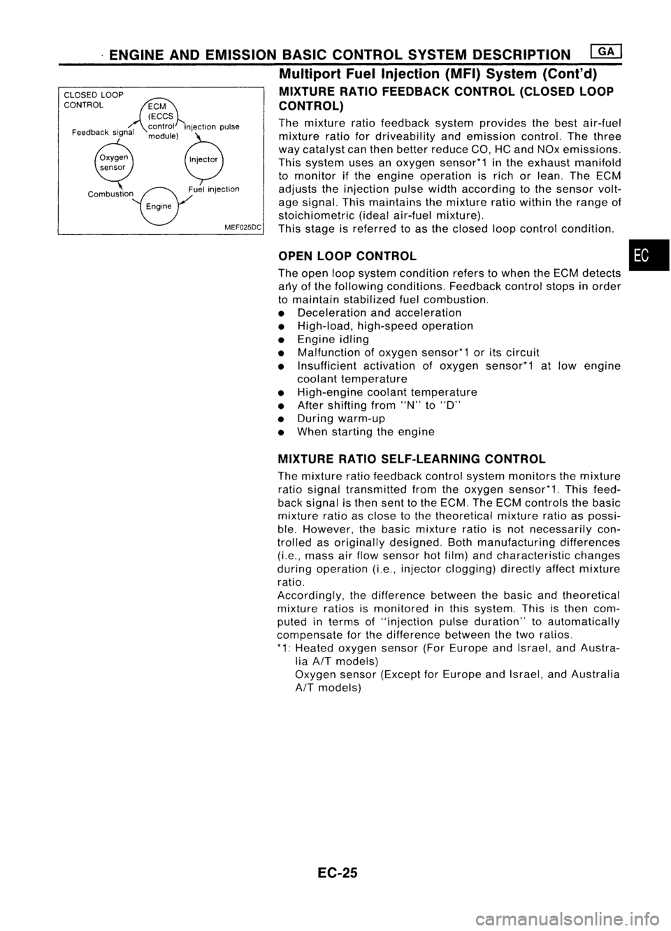
MIXTURE RATIOFEEDBACK CONTROL(CLOSEDLOOP
CONTROL)
The mixture ratiofeedback systemprovides thebest air-fuel
mixture ratiofordriveability andemission control.Thethree
way catalyst canthen better reduce CO,HCand NOx emissions.
This system usesanoxygen sensor*1 inthe exhaust manifold
to monitor ifthe engine operation isrich orlean. TheECM
adjusts theinjection pulsewidthaccording tothe sensor volt-
age signal. Thismaintains themixture ratiowithin therange of
stoichiometric (idealair-fuel mixture).
MEF025DC
Thisstage isreferred toas the closed loopcontrol condition .
Feedback
signal
CLOSED
LOOP
CONTROL
MIXTURERATIOSELF-LEARNING CONTROL
The mixture ratiofeedback controlsystem monitors themixture
ratio signal transmitted fromtheoxygen sensor*1. Thisfeed-
back signal isthen senttothe ECM. TheECM controls thebasic
mixture ratioasclose tothe theoretical mixtureratioaspossi-
ble. However, thebasic mixture ratioisnot necessarily con-
trolled asoriginally designed. Bothmanufacturing differences
(i.e., mass airflow sensor hotfilm) andcharacteristic changes
during operation (i.e.,injector clogging) directlyaffectmixture
ratio.
Accordingly, thedifference betweenthebasic andtheoretical
mixture ratiosismonitored inthis system. Thisisthen com-
puted interms of"injection pulseduration" toautomatically
compensate forthe difference betweenthetwo ratios.
* 1: Heated oxygen sensor(ForEurope andIsrael, andAustra-
lia AIT models)
Oxygen sensor(Except forEurope andIsrael, andAustralia
AIT
models)
EC-25
Page 752 of 1701
BASICSERVICE PROCEDURE
• FUEL PRESRELEASE. D
FUEL PUMP WILLSTOP BY
TOUCHING STARTDURING
IDLE.
CRANK AFEW TIMES AFTER
ENGINE STALL
---S-T~-RT--
SEF823K
Fuel
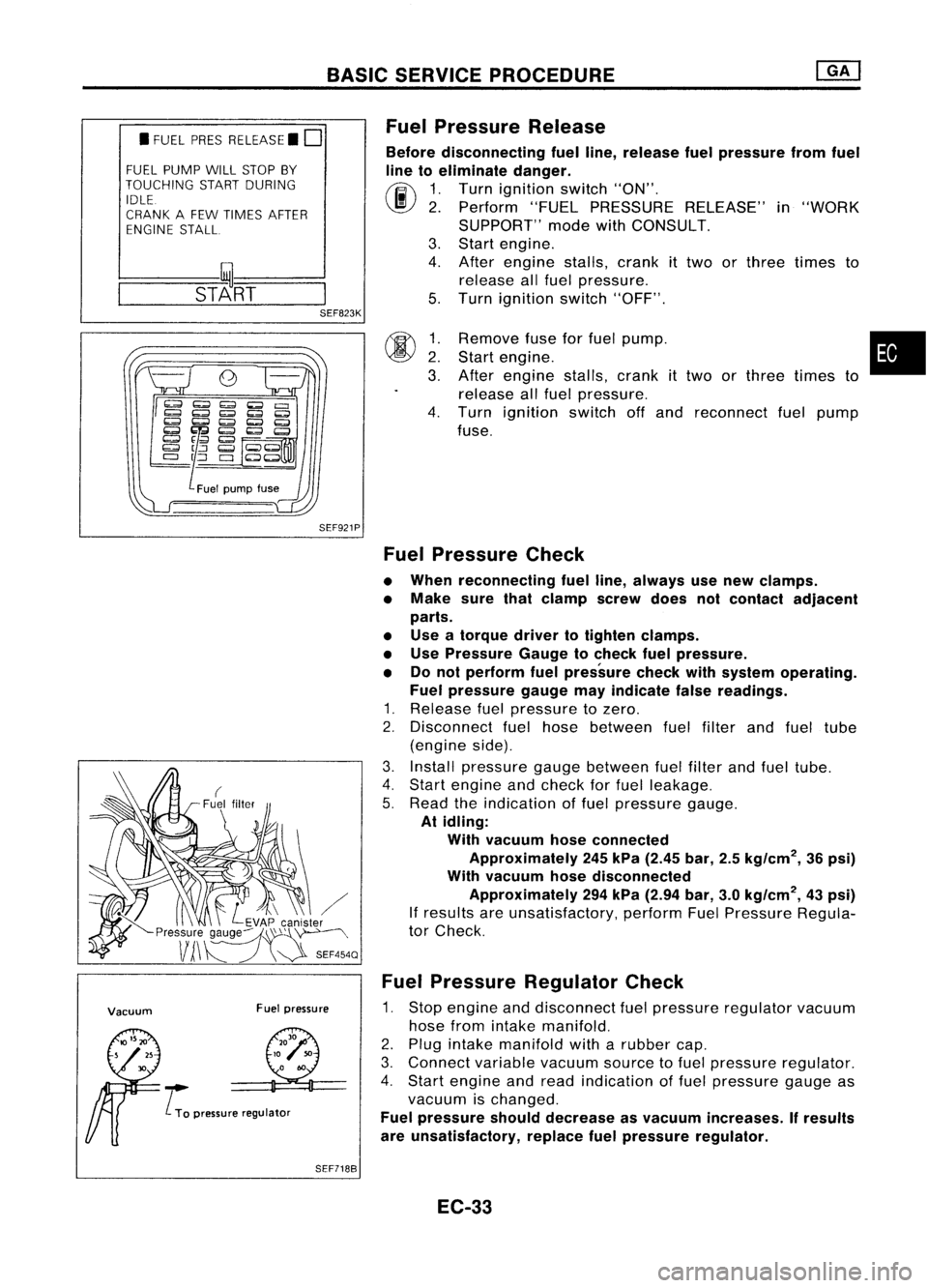
Pressure Release
Before disconnecting fuelline, release fuelpressure fromfuel
line toeliminate danger.
(ij\
1.Turn ignition switch"ON".
~ 2.Perform "FUELPRESSURE RELEASE"in"WORK
SUPPORT" modewithCONSULT.
3. Start engine.
4. After engine stalls,crankittwo orthree times to
release allfuel pressure.
5. Turn ignition switch"OFF".
SEF921P
00
~:
3.
4.
Remove
fuseforfuel pump. •
Start engine.
After engine stalls,crankittwo orthree times to
release allfuel pressure.
Turn ignition switchoffand reconnect fuelpump
fuse.
Vacuum Fuelpressure
..... L
To pressure regulator
Fuel
Pressure Check
• When reconnecting fuelline, always usenew clamps.
• Make surethatclamp screwdoesnotcontact adjacent
parts.
• Use atorque drivertotighten clamps.
• Use Pressure Gaugetocheck fuelpressure.
• Donot perform fuelpressure checkwithsystem operating.
Fuel pressure gaugemayindicate falsereadings.
1. Release fuelpressure tozero.
2. Disconnect fuelhose between fuelfilter andfuel tube
(engine side).
3. Install pressure gaugebetween fuelfilter andfuel tube.
4. Start engine andcheck forfuel leakage.
5. Read theindication offuel pressure gauge.
At idling:
With vacuum hoseconnected
Approximately 245kPa (2.45 bar,2.5kg/cm
2,
36psi)
With vacuum hosedisconnected
Approximately 294kPa (2.94 bar,3.0kg/cm
2,
43psi)
If results areunsatisfactory, performFuelPressure Regula-
tor Check.
Fuel Pressure Regulator Check
1. Stop engine anddisconnect fuelpressure regulator vacuum
hose fromintake manifold.
2. Plug intake manifold witharubber cap.
3. Connect variablevacuumsourcetofuel pressure regulator.
4. Start engine andread indication offuel pressure gaugeas
vacuum ischanged.
Fuel pressure shoulddecrease asvacuum increases. Ifresults
are unsatisfactory, replacefuelpressure regulator.
SEF7188
EC-33
Page 763 of 1701
ON-BOARDDIAGNOSTIC SYSTEMDESCRIPTION
\ I/
'e/'
-
CHECK-
/
.......
/ I\
Malfunction indicator
lamp SEF051PA
Malfunction
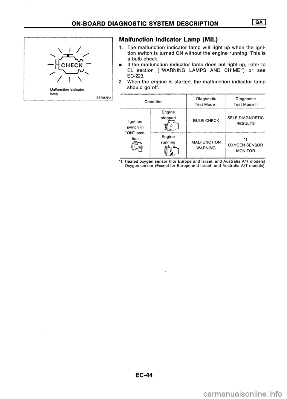
Indicatorlamp(Mil)
1. The malfunction indicatorlampwilllight upwhen theigni-
tion switch isturned ONwithout theengine running. Thisis
a bulb check.
• If
the malfunction indicatorlampdoes notlight up,refer to
EL section ("WARNING LAMPSANDCHIME") orsee
EC-223.
2. When theengine isstarted, themalfunction indicatorlamp
should gooff.
Condition Diagnostic
Diagnostic
Test Mode I TestMode II
Engine
stopped BULBCHECK SELF-DIAGNOSTIC
Ignition
~
RESULTS
switch in
"ON" posi-
tion Engine
*1
~
running
MALFUNCTION
OXYGENSENSOR
ID
WARNING
MONITOR
*1: Heated oxygen sensor(ForEurope andIsrael, andAustralia AITmodels)
Oxygen sensor(Except forEurope andIsrael, andAustralia AITmodels)
EC-44
Page 769 of 1701
ON-BOARDDIAGNOSTIC SYSTEMDESCRIPTION
CONSULT (Cont'd)
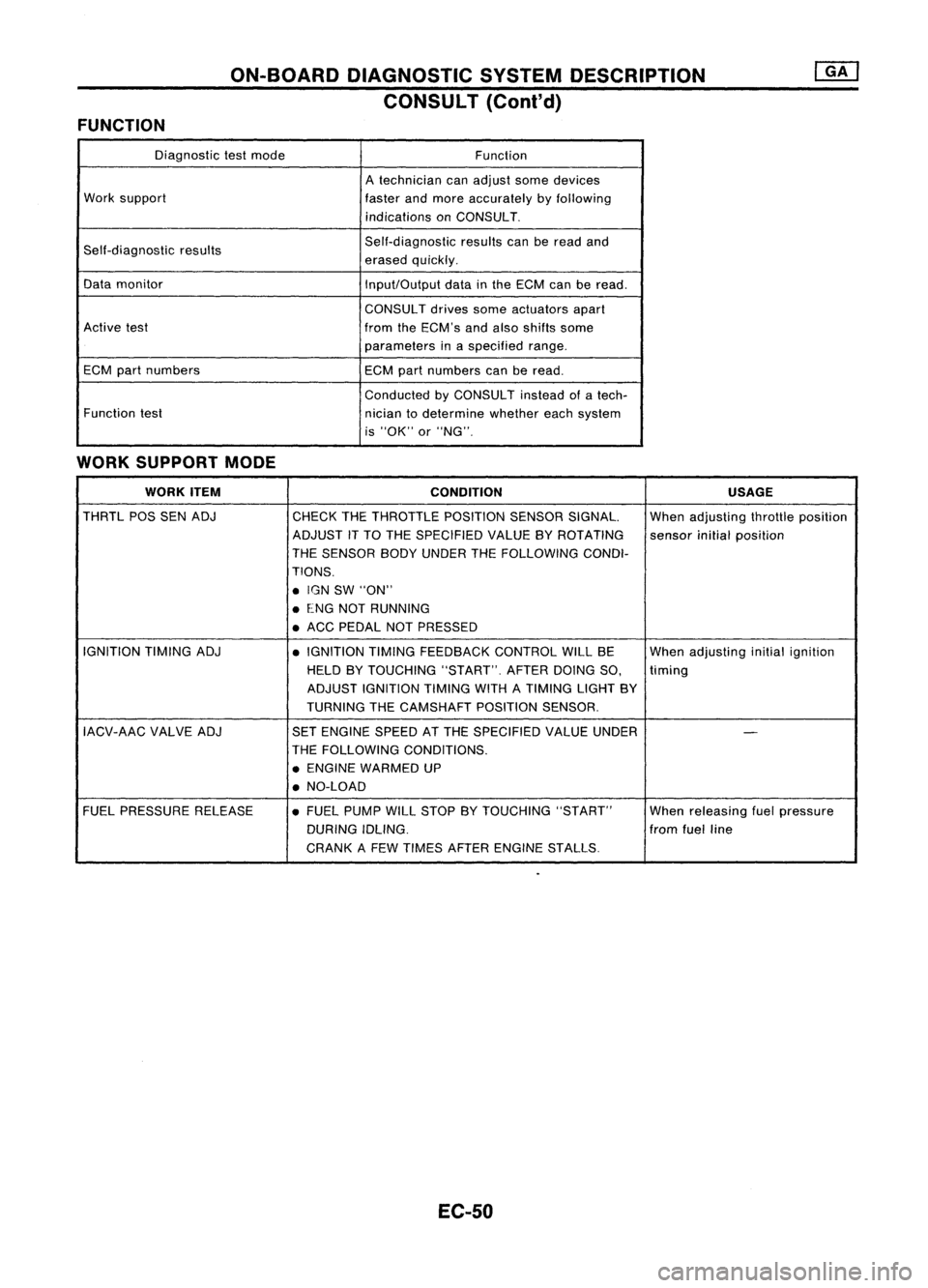
FUNCTION
Diagnostictestmode
Function
A technician canadjust somedevices
Work support
fasterandmore accurately byfollowing
indications onCONSULT.
Self-diagnostic results Self-diagnostic
resultscanberead and
erased quickly.
Data monitor
Input/Outputdatainthe ECM canberead.
CONSUL Tdrives someactuators apart
Active test
fromtheECM's andalso shifts some
parameters inaspecified range.
ECM partnumbers ECMpartnumbers canberead.
Conducted byCONSULT insteadofatech-
Function test
niciantodetermine whethereachsystem
is "OK" or"NG".
WORK SUPPORT MODE
WORK ITEM
CONDITION USAGE
THRTL POSSENADJ
CHECKTHETHROTTLE POSITIONSENSORSIGNAL. Whenadjusting throttleposition
ADJUST iTTO THE SPECIFIED VALUEBYROTATING
sensorinitialposition
THE SENSOR BODYUNDER THEFOLLOWiNG CONDI-
TIONS .
• IGN SW"ON"
• ENG NOTRUNNING
• ACC PEDAL NOTPRESSED
IGNITION TIMINGADJ
•IGNITION TIMINGFEEDBACK CONTROLWILLBE Whenadjusting initialignition
HELD BYTOUCHING "START".AFTERDOINGSO,
timing
ADJUST IGNITION TIMINGWITHATIMING LIGHTBY
TURNING THECAMSHAFT POSITIONSENSOR.
IACV-AAC VALVEADJ SETENGINE SPEEDATTHE SPECIFIED VALUEUNDER
-
THE FOllOWING CONDITIONS.
• ENGINE WARMED UP
• NO-LOAD
FUEL PRESSURE RELEASE •FUEL PUMP WillSTOP BYTOUCHING "START" Whenreleasing fuelpressure
DURING IDLING. fromfuelline
CRANK AFEW TIMES AFTER ENGINE STALLS.
EC-50
Page 770 of 1701
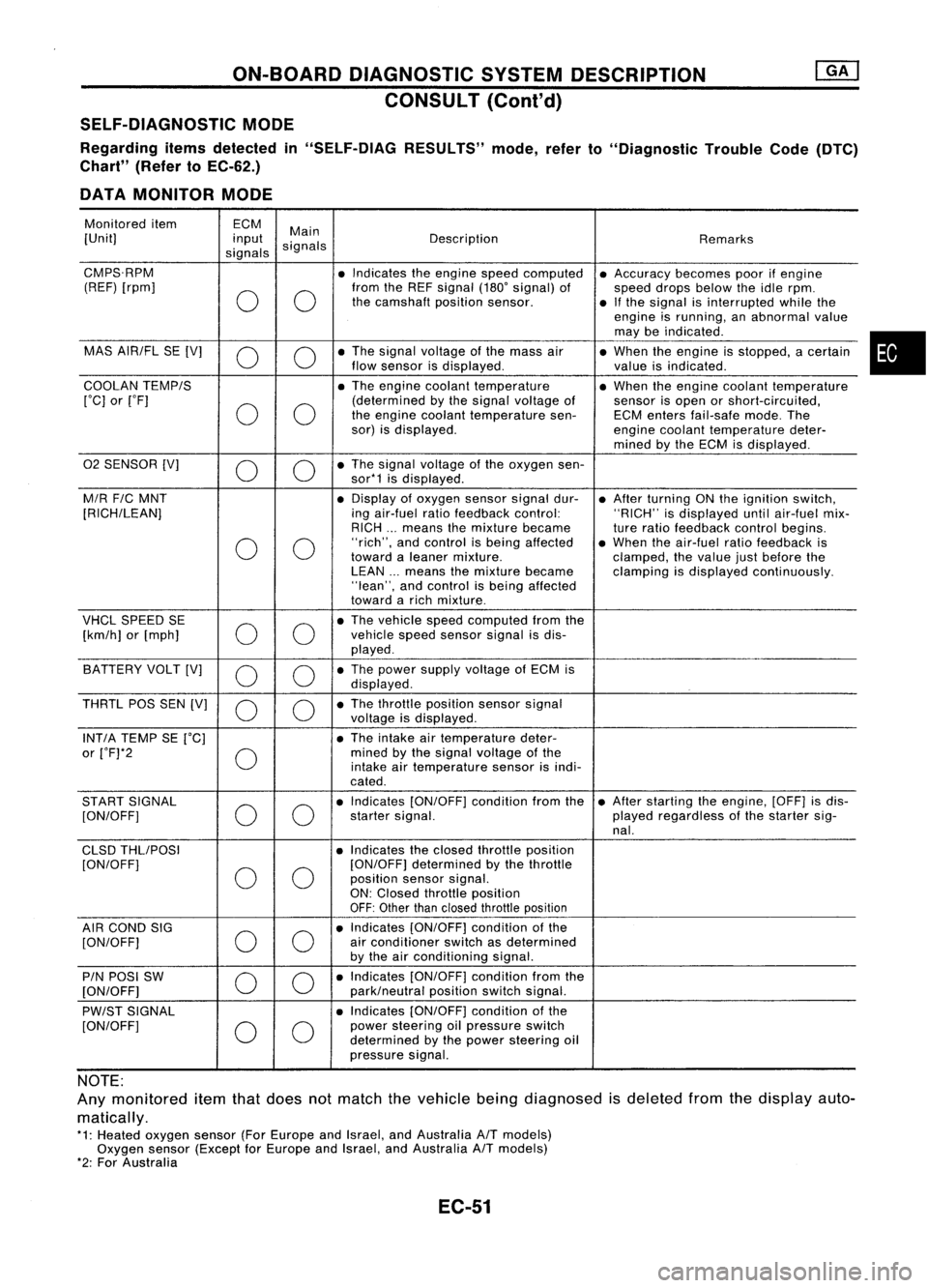
ON-BOARDDIAGNOSTIC SYSTEMDESCRIPTION
CONSULT (ConI'd)
SELF-DIAGNOSTIC MODE
Regarding itemsdetected in"SELF-DIAG RESULTS"mode,referto"Diagnostic TroubleCode(DTC)
Chart" (RefertoEC-62.)
DATA MONITOR MODE
Monitored item ECM
Main
[Unit] input
signals Description
Remarks
signals
CMPS.RPM •Indicates theengine speedcomputed •Accuracy becomespoorifengine
(REF) [rpm]
00
from
theREF signal (180'signal) of
speeddropsbelow theidle rpm.
the camshaft positionsensor.
•Ifthe signal isinterrupted whilethe
engine isrunning, anabnormal value
may beindicated .
MAS AIR/FL SE[V]
0 0
•
The signal voltage ofthe mass air
•When theengine isstopped, acertain
flow sensor isdisplayed .
valueisindicated.
COOLAN TEMP/S
•The engine coolant temperature •When theengine coolant temperature
['C] or['F]
00
(determined
bythe signal voltage of
sensorisopen orshort-circuited,
the engine coolant temperature sen-ECMenters fail-safe mode.The
sor) isdisplayed.
enginecoolant temperature deter-
mined bythe ECM isdisplayed .
02 SENSOR [V]
00
•
The signal voltage ofthe oxygen sen-
sor*1 isdisplayed .
M/R F/CMNT •
Display ofoxygen sensorsignaldur-
•After turning ONthe ignition switch,
[RICH/LEAN] ingair-fuel ratiofeedback control: "RICH"isdisplayed untilair-fuel mix-
RICH ...means themixture became
tureratio feedback controlbegins.
0 0
"rich",
andcontrol isbeing affected •When theair-fuel ratiofeedback is
toward aleaner mixture.
clamped,thevalue justbefore the
LEAN ...means themixture became clampingisdisplayed continuously.
"lean", andcontrol isbeing affected
toward arich mixture .
VHCL SPEED SE
00
•
The vehicle speedcomputed fromthe
[km/h] or[mph] vehicle
speedsensor signalisdis-
played .
BATTERY VOLT[V]
0 0
•
The power supply voltage ofECM is
displayed .
THRTL POSSEN[V]
0 0
•
The throttle position sensorsignal
voltage isdisplayed.
INT/A TEMP SE['C] •The intake airtemperature deter-
or ['F]*2
0
mined
bythe signal voltage ofthe
intake airtemperature sensorisindi-
cated .
START SIGNAL
00
•
Indicates [ON/OFF] conditionfromthe•After starting theengine, [OFF]isdis-
[ON/OFF] startersignal. playedregardless ofthe starter sig-
nal.
CLSD THLIPOSI •Indicates theclosed throttle position
[ON/OFF]
00
[ON/OFF]
determined bythe throttle
position sensorsignal.
ON: Closed throttle position
OFF: Other thanclosed throttle position
AIR COND SIG
00
•
Indicates [ON/OFF] conditionofthe
[ON/OFF] air
conditioner switchasdetermined
by the airconditioning signal.
PIN POSI SW
00
•
Indicates [ON/OFF] conditionfromthe
[ON/OFF] park/neutralpositionswitchsignal.
PW/ST SIGNAL •
Indicates [ON/OFF] conditionofthe
[ON/OFF]
00
power
steering oilpressure switch
determined bythe power steering oil
pressure signal.
NOTE:
Any monitored itemthatdoes notmatch thevehicle beingdiagnosed isdeleted fromthedisplay auto-
matically.
*1: Heated oxygen sensor(ForEurope andIsrael, andAustralia A/Tmodels)
Oxygen sensor(Except forEurope andIsrael, andAustralia A/Tmodels)
*2: For Australia
EC-51
•
Page 774 of 1701
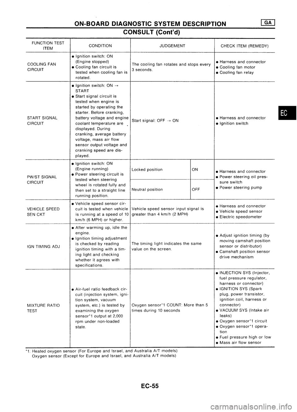
ON-BOARDDIAGNOSTIC SYSTEMDESCRIPTION
CONSULT (Conl'd)
FUNCTION TEST
CONDITION JUDGEMENT
ITEM CHECK
ITEM(REMEDY)
• Ignition switch:ON
COOLING FAN (Engine
stopped)
Thecooling fanrotates andstops every •
Harness andconnector
CIRCUIT •
Cooling fancircuit is
3seconds. •
Cooling fanmotor
tested whencooling fanis
•Cooling fanrelay
rotated .
• Ignition switch:ON-.
START
• Start signal circuit is
tested whenengine is
started byoperating the
starter. Beforecranking,
START SIGNAL batteryvoltage andengine
Startsignal: OFF-.ON •
Harness andconnector
CIRCUIT coolanttemperature are •
Ignition switch
displayed. During
cranking, averagebattery
voltage, massairflow
sensor outputvoltage and
cranking speedaredis-
played .
• Ignition switch:ON
(Engine running)
Lockedposition ON
•Harness andconnector
PW/ST SIGNAL •
Power steering circuitis
•Power steering oilpres-
tested whensteering
CIRCUIT wheelisrotated fullyand sure
switch
then settoastraight lineNeutral
position OFF•
Power steering pump
running position.
• Vehicle speedsensor cir-
•Harness andconnector
VEHICLE SPEED cuit
istested whenvehicle Vehicle
speedsensor inputsignal is
•Vehicle speedsensor
SEN CKT is
running ataspeed of10 greater
than4km/h (2MPH)
•Electric speedometer
km/h (6MPH) orhigher .
• After warming up,idle the
engine. •Adjust ignition timing(by
• Ignition timingadjustment
movingcamshaft position
IGN TIMING ADJ is
checked byreading The
timing lightindicates thesame
sensorordistributor)
ignition timingwithatim- value
onthe screen.
•Camshaft positionsensor
ing light andchecking
drivemechanism
whether itagrees with
specifications.
•INJECTION SYS(Injector,
fuel pressure regulator,
harness orconnector)
• Air-fuel ratiofeedback cir- •
IGNITION SYS(Spark
cuit (injection system,igni- plug,
power transistor,
tion system, vacuum ignition
coil,harness or
MIXTURE RATIO system,
etc.)istested byOxygen
sensor'1 COUNT:Morethan5 connector)
TEST examining
theoxygen times
during 10seconds •
VACUUM SYS(Intake air
sensor'1 outputat2,000 leaks)
rpm under non-loaded •
Oxygen sensor'1 circuit
state. •
Oxygen sensor'1 opera-
tion
• Fuel pressure highorlow
• Mass airflow sensor
'1: Heated oxygen sensor(ForEurope andIsrael, andAustralia AITmodels)
Oxygen sensor(Except forEurope andIsrael, andAustralia
A/T
models)
EC-55
•
Page 780 of 1701
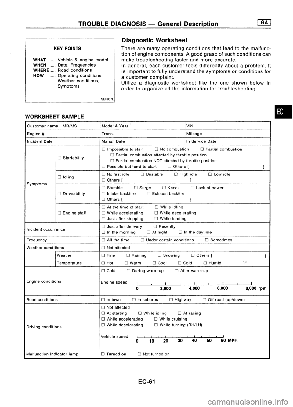
TROUBLEDIAGNOSIS -General Description
KEY POINTS
WHAT .....Vehicle &engine model
WHEN Date,Frequencies
WHERE Roadconditions
HOW Operatingconditions,
Weather conditions,
Symptoms
SEF907L
WORKSHEET SAMPLE
Diagnostic
Worksheet
There aremany operating conditions thatlead tothe malfunc-
tion ofengine components. Agood grasp ofsuch conditions can
make troubleshooting fasterandmore accurate.
In general, eachcustomer feelsdifferently aboutaproblem. It
is important tofully understand thesymptoms orconditions for
a customer complaint.
Utilize adiagnostic worksheet liketheone shown belowin
order toorganize allthe information fortroubleshooting.
•
Customer name
MR/MS Model
&
Year
.
VIN
Engine
#
Trans. Mileage
Incident Date Manu!.Date InService Date
o
Impossible tostart
o
No combustion
o
Partial combustion
o
Startability
o
Partial combustion affectedbythrottle position
LJ Partial combustion NOTaffected bythrottle position
o
Possible buthard tostart
o
Others [
1
o
Idling
o
No fast idle
o
Unstable
o
High idle
o
Low idle
o
Others [
1
Symptoms
o
Stumble
o
Surge
o
Knock
o
Lack ofpower
o
Driveability
i.J
Intake backfire
o
Exhaust backfire
o
Others [
1
o
At the lime ofstart
o
While idling
[.J
Engine stall
o
While accelerating
o
While decelerating
o
Just after stopping
o
While loading
Incident occurrence
o
Just after delivery
o
Recently
o
Inthe morning
o
At night
o
Inthe daytime
Frequency
o
All the time
o
Under certain conditions
o
Sometimes
Weather conditions
o
Not affected
Weather
o
Fine DRaining
o
Snowing
o
Others [
1
Temperature
o
Hot
o
Warm
o
Cool
o
Cold
o
Humid OF
o
Cold
o
During warm-up
o
After warm-up
Engine conditions
Enginespeed
I
I
I
I
I
I
I
I
I
0 2,000 4,000
6,000 8,000
rpm
Road conditions
o
Intown
o
Insuburbs
o
Highway
o
Off road (up/down)
o
Not affected
o
At starting
o
While idling
o
At racing
o
While accelerating
o
While cruising
Driving conditions
o
While decelerating
o
While turning (RH/LH)
Vehicle speed
I
,
I
I
I III
I
I
I
II
0 10 20 30
40
5060
MPH
Malfunction indicatorlamp
o
Turned on
o
Not turned on
EC-61
Page 784 of 1701
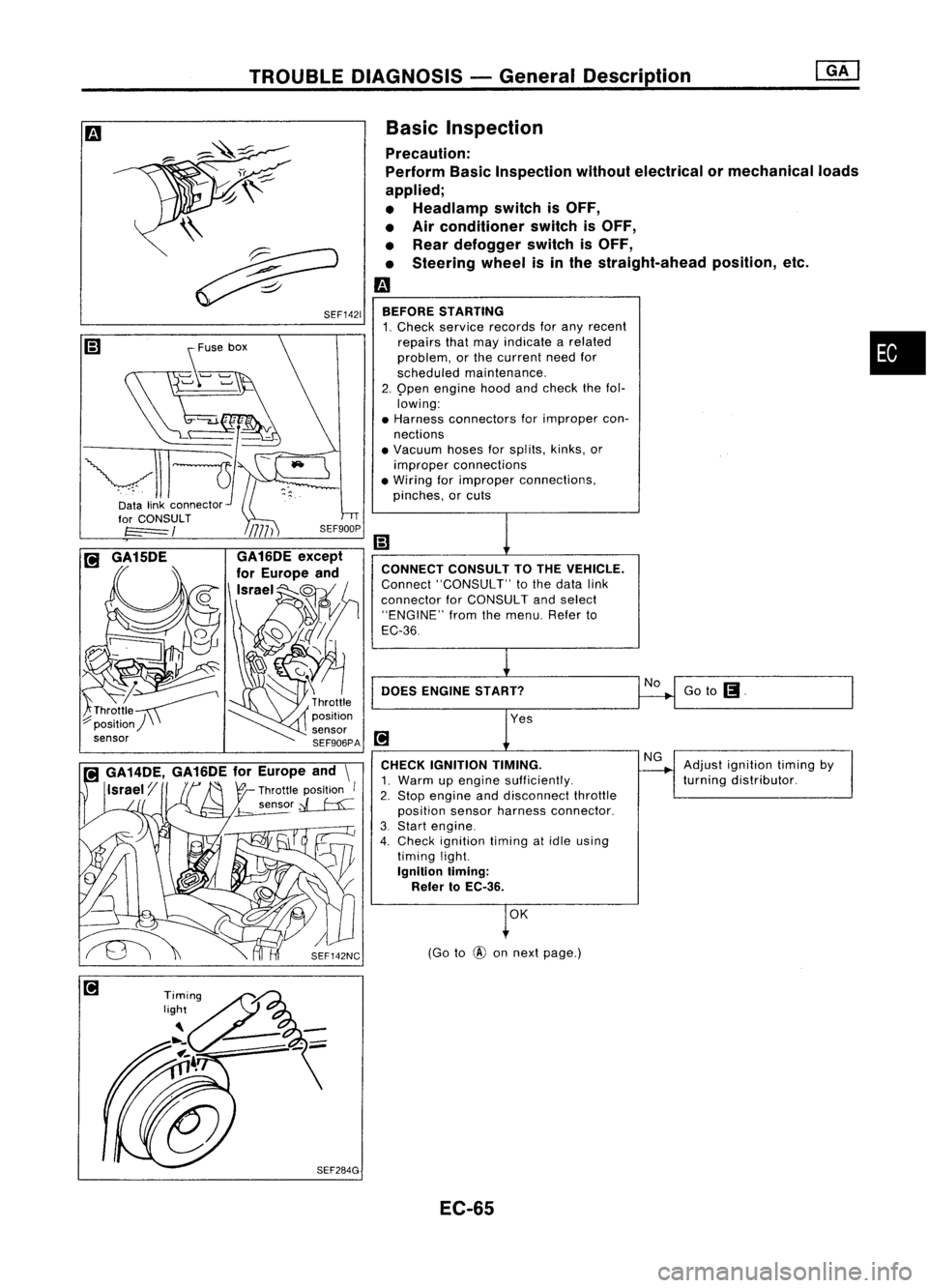
TROUBLEDIAGNOSIS -General Description
Goto
(J.
Adjust ignition timingby
turning distributor.
No
NG
(Go to
@
onnext page.)
OK
CONNECT
CONSULTTOTHE VEHICLE.
Connect "CONSULT" tothe data link
connector forCONSULT andselect
"ENGINE" fromthemenu. Referto
EC-36
DOES ENGINE START?
BEFORE
STARTING
1. Check service records forany recent
repairs thatmay indicate arelated •
problem, orthe current needfor
scheduled maintenance.
2. 9pen engine hoodandcheck thefol.
lowing:
• Harness connectors forimproper con-
nections
• Vacuum hosesforsplits, kinks,or
improper connections
• Wiring forimproper connections,
pinches, orcuts
CHECK IGNITION TIMING.
1. Warm upengine sufficiently.
2. Stop engine anddisconnect throttle
position sensorharness connector.
3. Start engine.
4. Check ignition timingatidle using
timing light.
Ignition liming:
Refer toEC-36.
Basic
Inspection
Precaution:
Perform BasicInspection withoutelectrical or
mechanical loads
applied;
• Headlamp switchisOFF,
• Air conditioner switchisOFF,
• Rear defogger switchisOFF,
• Steering wheelisin the straight-ahead position,etc.
m
\\
~
~ SEF1421
~use box
~-~
vll-JI-
Datalinkconnector~'
EC-65