1995 NISSAN ALMERA N15 stop start
[x] Cancel search: stop startPage 373 of 1701

ELECTRICALSYSTEM
SECTION
EL
When youread wiring diagrams:
• Read GIsection, "HOWTOREAD WIRING DIAGRAMS".
When youperform troublediagnos.es, readGIsection, "HOWTOFOllOW FLOWCHART
IN TROUBLE DIAGNOSES" and"HOW TOPERFORM EFFICIENT DIAGNOSIS FORAN
ELECTRICAL INCIDENT".
CONTENTS
PRECAUTIONS 4
Supplemental RestraintSystem(SRS)"AIR
BAG" (DualAirBag System) 4
Supplemental RestraintSystem(SRS)"AIR
BAG" (Single AirBag System) 4
HARNESS CONNECTOR 5
Description 5
STANDARDIZED RELAy 6
Description 6
POWER SUPPLY ROUTING 8
Schematic 8
Wiring Diagram -POWER - 10
Fuse 19
Fusible Link 19
Circuit Breaker 19
GROUND DISTRIBUTION 20
BATTERy 25
How toHandle Battery 25
Battery TestandCharging Chart.. 28
Service DataandSpecifications (SOS) 32
STARTING SySTEM
33
Wiring Diagram -START - 33
Trouble Diagnoses 35
Construction 36
Removal andInstallation .45
Magnetic SwitchCheck .46
Pinion/Clutch Check 46
Brush Check 46
Yoke Check 47
Armature Check 48
Assembly .49
Service DataandSpecifications (SDS) 50
CHARGING SYSTEM 52
Wiring Diagram -CHARGE - 52
Trouble Diagnoses 54Construction
55
Removal andInstallation 57
Disassembly 57
Rotor Check 57
Brush Check 58
Stator Check 58
Diode Check 59
Assembly 60
Service DataandSpecifications (SDS) 61
COMBINATION SWITCH 62
Combination Switch/Check 62
Replacement 64
HEADLAMP -Without Daytime lightSystem -65
Wiring Diagram -H/LAMP - 65
Trouble Diagnoses 67
HEADLAMP -Daytime lightSystem - 68
Operation (Daytimelightsystem) 68
System Description 69
Schematic 70
Wiring Diagram -DTRL - 71
Trouble Diagnoses (DaytimeLight) 74
HEADLAMP 75
Bulb Replacement... 75•
Aiming Adjustment. 75
HEADLAMP -Headlamp Aiming
Control- 77
Wiring Diagram -AIM - 77
Description 81
EXTERIOR LAMP 82
Clearance, LicenseandTail Lamps/Schematic 82
Clearance, LicenseandTail Lamps/Wiring
Diagram -TAILIL - 83
Stop Lamp/Wiring Diagram-STOP/L - 92
Back-up Lamp/Wiring Diagram-BACK/L -94
Front FogLamp/Wiring Diagram-F/FOG -96
Front FogLamp BulbReplacement 101
Page 381 of 1701
![NISSAN ALMERA N15 1995 Service Manual POWERSUPPLY ROUTING
Schematic (Cont'd)
l5A~
F/FOG
20A
@J
LOAD,DEF
lOA
[8J
ABS,SToP/L
lOA
[ill
TURN
FICO, A!CCUT,
HEATER, A!e
HEATER, A!e
7.5A@Q]
lOA
@]
l5A
[ill
INT/L
GLOW, AIM,BUZZ NISSAN ALMERA N15 1995 Service Manual POWERSUPPLY ROUTING
Schematic (Cont'd)
l5A~
F/FOG
20A
@J
LOAD,DEF
lOA
[8J
ABS,SToP/L
lOA
[ill
TURN
FICO, A!CCUT,
HEATER, A!e
HEATER, A!e
7.5A@Q]
lOA
@]
l5A
[ill
INT/L
GLOW, AIM,BUZZ](/manual-img/5/57349/w960_57349-380.png)
POWERSUPPLY ROUTING
Schematic (Cont'd)
l5A~
F/FOG
20A
@J
LOAD,DEF
lOA
[8J
ABS,SToP/L
lOA
[ill
TURN
FICO, A!CCUT,
HEATER, A!e
HEATER, A!e
7.5A@Q]
lOA
@]
l5A
[ill
INT/L
GLOW, AIM,BUZZER,
HORN, AUDIO, NATS
ILL, AUDIO
WIP/R
ACCESSORY
RELAY
20A
[ill
lOA ~
l5A ~ HORN
WIPER
MIRROR, DEF
HLC
20A []]
•
LOAD,
DEF
LOAD, MIL,BUZZER, WINDOW,
SROOF, DEF,NATS
LKUP, AIT,BACK/L,
METER, WARN
TURN
ABS
H/SEAT
H02S
F/PUMP, AIRREG
SRS
SRS
PGC/V, EGRC/V, AAC/V,VTC,
COOL/F, LOAD,GLOW,PLA,
FCUT, A/C,START, DTRL,DEF
3A
IE]
lOA
[ill
lOA
[ill
lOA ~
l5A
@]
7.
5A
[ill
n
IGNITION
U
RELAY
TAIL. F/FoG
LOAD, AIM,TAIL, F/FO~
ILL, BUZZER
RHO
models
eo engine
SR engine
SR engine A/Tmodels
and COengine
For Europe andIsrael
Except
@
LHD models without
daytime lightsystem
Except
@
LHo models with
daytime lightsystem
Without daytime lightsystem
With single airbag system
With dualairbag system
@
@
@
@
@
@
@
@
@
@
@
@)
HEL096
EL-9
Page 397 of 1701
SEL711EBATTERY
CAUTION:
• If
itbecomes necessary tostart theengine withabooster
battery andjumper cables, usea12-volt booster battery.
• After connecting batterycables, ensurethatthey aretightly
clamped tobattery terminals forgood contact.
• Never adddistilled waterthrough thehole used tocheck
specific gravity.
How toHandle Battery
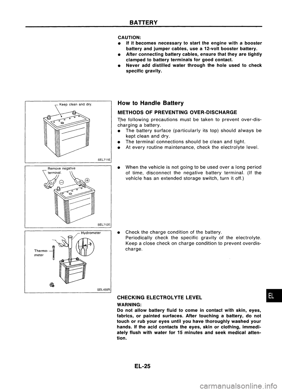
METHODS OFPREVENTING OVER-DISCHARGE
T.he following precautions mustbetaken toprevent over-dis-
charging abattery.
• The battery surface (particularly itstop) should always be
kept clean anddry.
• The terminal connections shouldbeclean andtight.
• Atevery routine maintenance, checktheelectrolyte level.
SEL459R
•
When thevehicle isnot going tobe used overalong period
of time, disconnect thenegative batteryterminal. (Ifthe
vehicle hasanextended storageswitch,turnitoff.)
• Check thecharge condition ofthe battery.
Periodically checkthespecific gravityofthe electrolyte.
Keep aclose check oncharge condition toprevent overdis-
charge.
CHECKING ELECTROLVTELEVEL •
WARNING: Do not allow battery fluidtocome incontact withskin, eyes,
fabrics, orpainted surfaces. Aftertouching abattery, donot
touch orrub your eyes untilyouhave thoroughly washedyour
hands. Ifthe acid contacts theeyes, skinorclothing, immedi-
ately flush withwater for15minutes andseek medical atten-
tion.
EL-25
Page 402 of 1701
BATTERY
Battery TestandCharging Chart(Cont'd)
I
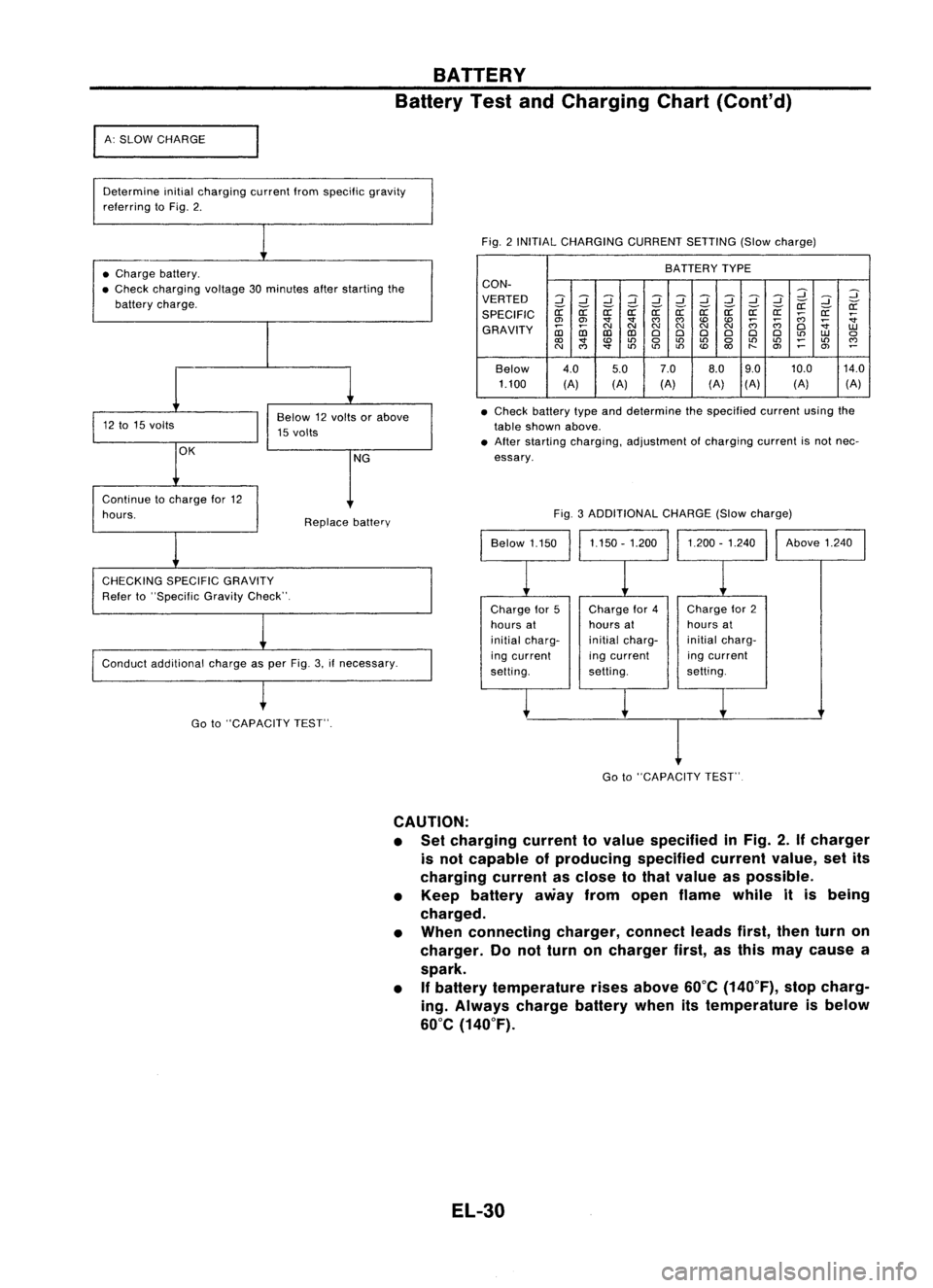
A: SLOW CHARGE
Determine initialcharging currentIromspecilic gravity
relerring toFig. 2.
Fig.2INITIAL CHARGING CURRENTSETTING(Slowcharge)
• Charge battery.
• Check charging voltage30minutes afterstarting the
battery charge. BATTERY
TYPE
CON-
VERTED
2
::J
2
::J
::J
2
::J
2
::J
::J
2
2
::J
if ifif if if
r:r:
if
SPECIFIC
r:r:
r:r: r:r:r:r:r:r:
;;;
r:r:
:;
en en
'
""""
;;;;;;
:;
GRAVITY
~
NNN
NN
N
0
1.U
CD CDCDCD
000 000
to
1.U
0
<0
'
0
to
LO
0
LOLO
~
LO
""
N
""
'
toto
LO
<0
"-
en
~
en
~
Below 4.0
5.07.0
8.09.0 10.0
14.0
1.100 (A)(A)(A) (A)(A)
(A) (A)
• Check battery typeanddetermine thespecified currentusingthe
table shown above.
• After starting charging, adjustment ofcharging currentisnot nec-
essary.
Conduct additional chargeasper Fig. 3.ifnecessary. Fig.
3ADDITIONAL CHARGE(Slowcharge)
Continue
tocharge lor12
hours.
CHECKING SPECIFICGRAVITY
Reier to"Specilic GravityCheck". Replace
battery
Chargefor5
hours at
initial charg-
ing current
selting. Charge
lor4
hours at
initial charg-
ing current
setting. Charge
lor2
hours at
initial charg-
ing current
setting. Above
1.240
Go to"CAPACITY TEST".
I
Go to"CAPACITY TEST"
CAUTION:
• Set charging currenttovalue specified inFig. 2.
If
charger
is not capable ofproducing specifiedcurrentvalue,setits
charging currentasclose tothat value aspossible.
• Keep battery awayfromopen flame whileitis being
charged.
• When connecting charger,connectleadsfirst,thenturnon
charger. Donot turn oncharger first,asthis may cause a
spark.
• If
battery temperature risesabove 60°C(140°F), stopcharg-
ing. Always chargebatterywhenitstemperature isbelow
60°C (140°F).
EL-30
Page 403 of 1701
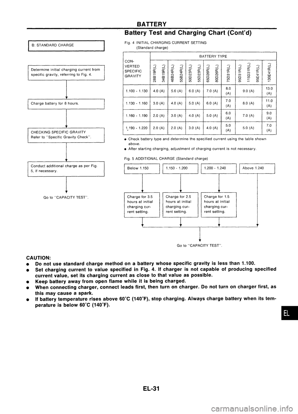
•Check battery typeanddetermine thespecified currentusingthetable shown
above .
• After starting charging, adjustment ofcharging currentisnot necessary.
BATTERY
Battery TestandCharging Chart(Cont'd)
BATTERY TYPE
CON-
VERTED
::J::J
~::J
::J
::J::J ::J ::J
::J
:J
:J
~
SPECIFIC
er:-
er:-
a:
er:-er:- er:-er:- er:- er:- er:-er:-
a:
;:;:;
a:
:;
0> 0> '1"'1"
(')
(')
to to
;:;:;
~
:;
GRAVITY
coco
C'J
C'J C'J
C'JC'J
C'J
(')
D
UJ
co co
DDD D D
D
L!)
UJ
a
to
L!)
a
L!)
L!)
a
L!)
L!)
~
L!)
~
C'J
(')
'1"
L!)
L!)L!)
to
O>
~
OJ
1.100 -1.130 4.0(A) 5.0(A) 60(A) 7.0(A) 8.0
130
(A) 90
(A)
(A)
1.130 -1160 30(Al 4.0(Al 5.0
(A) 6.0(A) 7.0
11.0
(A) 8.0
(A)
(A)
1.160 -1.190 2.0(A) 3.0(Al 4.0
(A)
5.0(Al 6.0
7.0(A) 9.0
(A) (A)
1.190 -1.220 2.0(A) 2.0(A) 3.0(A) 4.0
(A) 5.0
7.0
(A) 5.0
(A)
(A)
Fig. 5ADDITIONAL CHARGE(Standard charge)
Above1240
1.200 -1.240
1.150 -1.200
Below 1.150
Fig.
4INITIAL CHARGING CURRENTSETTING
(Standard charge)
Determine initialcharging currentfrom
specific gravity,referring toFig. 4.
Charge batteryfor8hours.
CHECKING SPECIFICGRAVITY
Refer to"Specific GravityCheck".
Conduct additional chargeasper Fig.
5, ifnecessary.
I
B: STANDARD CHARGE
Go to"CAPACITY TEST". Charge
for3.5
hours atinitial
charging cur-
rent setting. Charge
for2.5
hours atinitial
charging cur-
rent setting. Charge
for1.5
hours atinitial
charging cur-
rent setting.
I
Go to"CAPACITY TEST".
CAUTION:
• Donot use standard chargemethod onabattery whosespecific gravityisless than 1.100.
• Set charging currenttovalue specified inFig. 4.Ifcharger isnot capable ofproducing specified
current value,setitscharging currentasclose tothat value aspossible.
• Keep battery awayfromopen flame whileitis being charged.
• When connecting charger,connectleadsfirst,thenturnoncharger. Donot turn oncharger first,as
this may cause aspark.
• Ifbattery temperature risesabove 60°C(140°F), stopcharging. Alwayschargebatterywhenitstem-
perature isbelow 60°C(140°F).
•
EL-31
Page 404 of 1701
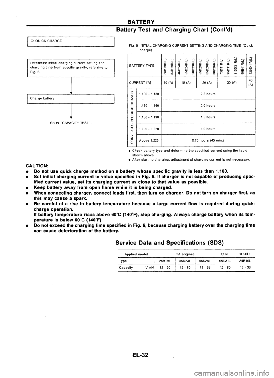
I
C: QUICK CHARGE
Determine initialcharging currentsettingand
charging timefrom specific gravity,referring to
Fig. 6.
I
Charge battery.
Goto"CAPACITY TEST".
BATTERY
Battery TestandCharging Chart(Cont'd)
Fig. 6INITIAL CHARGING CURRENTSETTINGANDCHARGING TIME(Quick
charge)
:::J:::J:::J:::J :::J:::J:::J
d dd
:::J
:::J :::J
~ ~
SA TTERY TYPE
~
~ ~~~~ ~a: a:a:
;;:;
~
~
0>
0>
""
""
C')
C')
CDCD
;;:;
;;:;
~
co co
C\I
N
C\I
N
C\I
N
Cl
W
D:l D:l
ClCl ClCl ClCl
L()
W
0
to
""
CD
L()
0
L()
L()
0
L()
L()
;:
L()
~
N
C')
""
L()
L()L()
CD
to
t-
O>
0>
CURRENT [A]10(A) 15(A) 20(A) 30(A) 40
(A)
>-
I-
1.100 -1.130 2.5
hours
:>
a:
(!J 1.130 -1.160 2.0
hours
0
u::
U
w
1.160 -1.190 1.5hours
0-
w
Cl
w
1.190 -1.220 1.0hours
I-
a:
w
>
z
0
Above 1.220 0.75
hours (45min.)
0
• Check battery typeanddetermine thespecified currentusingthetable
shown above.
• After starting charging, adjustment ofcharging currentisnot necessary.
CAUTION: • Donot use quick charge method onabattery whosespecific gravityisless than 1.100.
• Set initial charging currenttovalue specified inFig. 6.Ifcharger isnot capable ofproducing spec-
ified current value,setitscharging currentasclose tothat value aspossible.
• Keep battery awayfromopen flame whileitis being charged.
• When connecting charger,connectleadsfirst,thenturnoncharger. Donot turn oncharger first,as
this may cause aspark.
• Becareful ofarise inbattery temperature becausealarge current flowisrequired duringquick-
charge operation.
If
battery temperature risesabove 60°C(140°F), stopcharging. Alwayschargebatterywhenitstem-
perature isbelow 60°C(140°F).
• Donot exceed thecharging timespecified inFig. 6,because charging batteryoverthecharging time
can cause deterioration ofthe battery.
Service DataandSpecifications (SOS)
Applied model GA
engines CD20SR20DE
Type 26S19L
55D23L65D26L 95D31L
34S19L
Capacity V-AH
12-30 12
-60 12-65 12-80 12
-33
EL-32
Page 407 of 1701
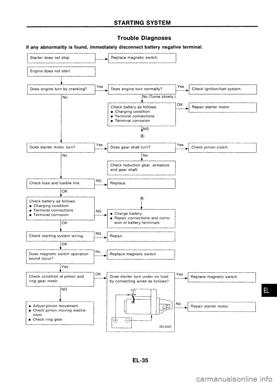
STARTINGSYSTEM
Trouble Diagnoses
If any abnormality isfound, immediately disconnectbatterynegative terminal.
Starter doesnotstop.
Engine doesnotstart. Replace
magnetic switch.
Does engine turnbycranking? Doesengine turnnormally? Check
ignition/fuel system.
No No
(Turns slowly.)
Check battery asfollows:
OK
Repairstarter motor.
• Charging condition
• Terminal connections
• Terminal corrosion
NG
@
Does starter motorturn? Yes
Doesgearshaft turn? Checkpinionclutch.
No No
Check reduction gear,armature
and gear shaft.
Check fuseandfusible link. Replace.
OK
Check battery asfollows:
@
• Charging condition
• Terminal connections
NG
• Terminal corrosion •
Charge battery.
• Repair connections andcorro-
OK
sian
ofbattery terminals.
Check starting systemwiring.
Repair.
OK
Does magnetic switchoperation No
Replace magnetic switch
sound occur?
Yes
Check condition ofpinion and
OK
Doesstarter turnunder noload Yes
Replace magnetic switch.
ring gear mesh.
byconnecting wiresasfollows?
NG
•
• Adjust pinionmovement.
Repairstarter motor.
• Check pinionmoving mecha-
nism .
• Check ringgear.
SELOO9Z
EL-35
Page 408 of 1701
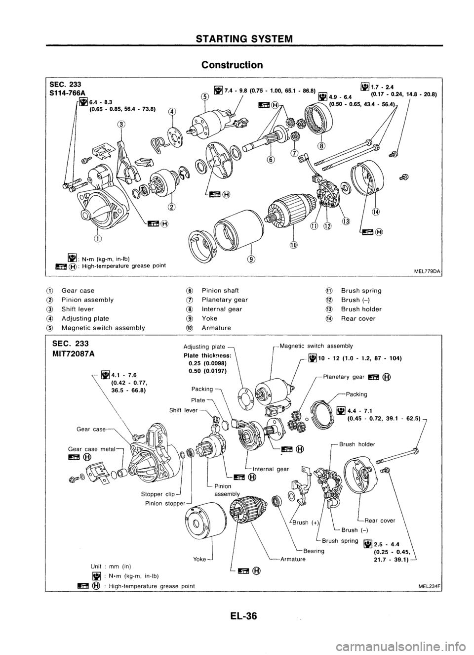
STARTINGSYSTEM
Construction
SEC. 233
S114-766A
~6.4.8.3
(0.65 -0.85, 56.4•73.8)
~: N.m(kg-m, in-Ib)
a
@:
High-temperature greasepoint
r.ii1
iii
1.7 •2.4
III 7.4-9.8 (0.75 -1.00, 65.1•86.8) ~4.9_6.4 (0.17_0.24, 14.8•20.8)
(0.50 -0.65, 43.4•56.4)
MEL779DA
G)
Gear case
@
Pinion assembly
@
Shift lever
@
Adjusting plate
@
Magnetic switchassembly
@
Pinion shaft
(J)
Planetary gear
@
Internal gear
@ Yoke
@
Armature
@
Brush spring
@
Brush
H
@
Brush holder
@
Rear cover
MEL234F
Ii!
2.5 -4.4
(0.25 -0.45,
21.7 -39.1)
Brush
holder
-Planetary
gear
m
@
~paCking
~4.4-7.1
o
(0.45-0.72, 39.1-62.5)
-Magnetic
switchassembly
~10 •12 (1.0 -1.2, 87-104)
Adjusting
plate~
Plate thickness:
0.25 (0.0098)
0.50 (0.0197)
Packing
0
Plate KJo
~
~m@
L
Internal g~ar
0
m@
Yoke
Pinion
stopper
Unit :mm (in)
Ii! :
N'm (kg-m, in-Ib)
m
@:
High-temperature greasepoint
SEC.
233
MIT72087A
EL-36