Page 307 of 1701
Togglelever
Stopper
Front
V
PARKING
BRAKECONTROL
Adjustment
Before orafter adjustment, payattention tothe following points.
a. For rear discbrake besure thattoggle leverreturns to
stopper whenparking brakeleverisreleased.
b. There isno drag when parking brakeleverisreleased.
SBR029D
SBR042D
1.
Adjust clearance betweenshoeanddrum/pad androtor as
follows:
a. Release parkingbrakeleverandloosen adjusting nut.
b.- Depress brakepedalfullyatleast 10times withengine run-
ning.
2. Pull control lever4-5 notches. Thenadjust control leverby
turning adjusting nut.
196 N(20 kg,44Ib)
/
SBR073D
3.
Pull control leverwithspecified amountofforce. Check
lever stroke andensure smooth operation.
Number ofnotches:
Drum brake: 7-
8
Disc brake: 8-
9
4. Bend warning lampswitchplate toensure following. Warn-
ing lamp comes onwhen leverispulled "A"notches and
goes outwhen fullyreleased.
Number of
"A"
notches: 1or less
BR-37
•
Page 323 of 1701
.=J
MPH
-~s::~
~~
___ --- warnin:1
TROUBLE
DIAGNOSES
Self-diagnosis (ForEurope)
FUNCTION
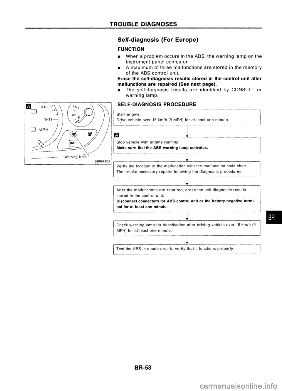
• When aproblem occursinthe ABS, thewarning lamponthe
instrument panelcomes on.
• Amaximum ofthree malfunctions arestored inthe memory
of the ABS control unit.
Erase theself-diagnosis resultsstoredinthe control unitafter
malfunctions arerepaired (Seenextpage).
• The self-diagnosis resultsareidentified byCONSULT or
warning lamp.
SELF-DIAGNOSIS PROCEDURE
Start engine.
Dr.ive vehicle over15km/h (9MPH) foratleast oneminute .
Stop vehicle withengine running.
Make surethaitheASS warning lampactivates.
SBR875CA
Verifythelocation ofthe malfunction withthemalfunction codechart.
Then make necessary repairsfollowing thediagnostic procedures.
After themalfunctions arerepaired, erasetheself-diagnostic results
stored inthe control unit.
Disconnect connectors forASS control unitorthe battery negative termi-
nal foratleast oneminute.
Check warning lampfordeactivation afterdriving vehicle over15km/h (9
MPH) foratleast oneminute.
Test theASS inasafe area toverify thatitfunctions properly.
BR-53
•
Page 329 of 1701
![NISSAN ALMERA N15 1995 Service Manual TROUBLEDIAGNOSES
Ii)
NISSAN
CONSULT
EE940.
I
~
I
START
I
SUB
MODE
,
SEF253Q
@]
~
SELECT
SYSTEM
0
ENGINE
AfT
AIRBAG ABS
IVMS
SBR104D
@]
I~
SELECT DIAGMODE
01
I
SELF-DIAG
RESULTS NISSAN ALMERA N15 1995 Service Manual TROUBLEDIAGNOSES
Ii)
NISSAN
CONSULT
EE940.
I
~
I
START
I
SUB
MODE
,
SEF253Q
@]
~
SELECT
SYSTEM
0
ENGINE
AfT
AIRBAG ABS
IVMS
SBR104D
@]
I~
SELECT DIAGMODE
01
I
SELF-DIAG
RESULTS](/manual-img/5/57349/w960_57349-328.png)
TROUBLEDIAGNOSES
Ii)
NISSAN
CONSULT
EE940.
I
~
I
START
I
SUB
MODE
,
SEF253Q
@]
~
SELECT
SYSTEM
0
ENGINE
AfT
AIRBAG ABS
IVMS
SBR104D
@]
I~
SELECT DIAGMODE
01
I
SELF-DIAG
RESULTS
,
I
DATA
MONITOR
I
I
ACTIVE
TEST
I
ECU
PART NUMBER
I
I
SST412B
II
•SELF-DiAG RESULTS.
0
FAILURE DETECTED
TIME
FR RH SENSOR
0
[OPEN)
ERASE
II
PRINT
SBR950C CONSULT
Inspection Procedure
SELF-DIAGNOSIS PROCEDURE
m
1) Turn ignition switchOFF.
2) Connect CONSULT toData LinkCon-
nector forCONSULT.
1) Start engine.
2) Drive vehicle over30km/h (20MPH)
for atleast oneminute.
.
r
(;)
1)Stop vehicle withengine running
and touch "START" onCON-
SUL Tscreen.
• Program
card
AE950: ForAustralia
EE940: ExceptAustralia
(!]
2)Touch "ASS".
lP]
3)Touch "SELF-DIAG RESULTS".
• The screen showsthedetected mal-
function andthetimes ofignition
switch ONand OFF after itoccurred.
Make thenecessary repairsfollowing
the diagnostic procedures.
II
After themalfunctions arerepaired,
erase theself-diagnostic resultsstored
in the control unitbytouching
"ERASE".
Check warning lampfordeactivation
after driving vehicle over30km/h (20
MPH) foratleast oneminute.
Test theASS inasafe area toverify
that itfunctions properly.
Note: "SELF.DlAG RESULTS"screenshowsthedetected malfunction and
the times ofignition switchONand OFF after
it
occurred.
BR-59
•
Page 352 of 1701
TROUBLEDIAGNOSES
Diagnostic Procedure8
CONTROL UNIT
(Malfunction codeNo.71)
Carry outself-diagnosis aftererasing
self-diagnostic results,BR-56.
Does warning lampindicate codeNo.
71 again?
No
Inspect thesystem according tothe
code No. Yes
Replace controlunit.
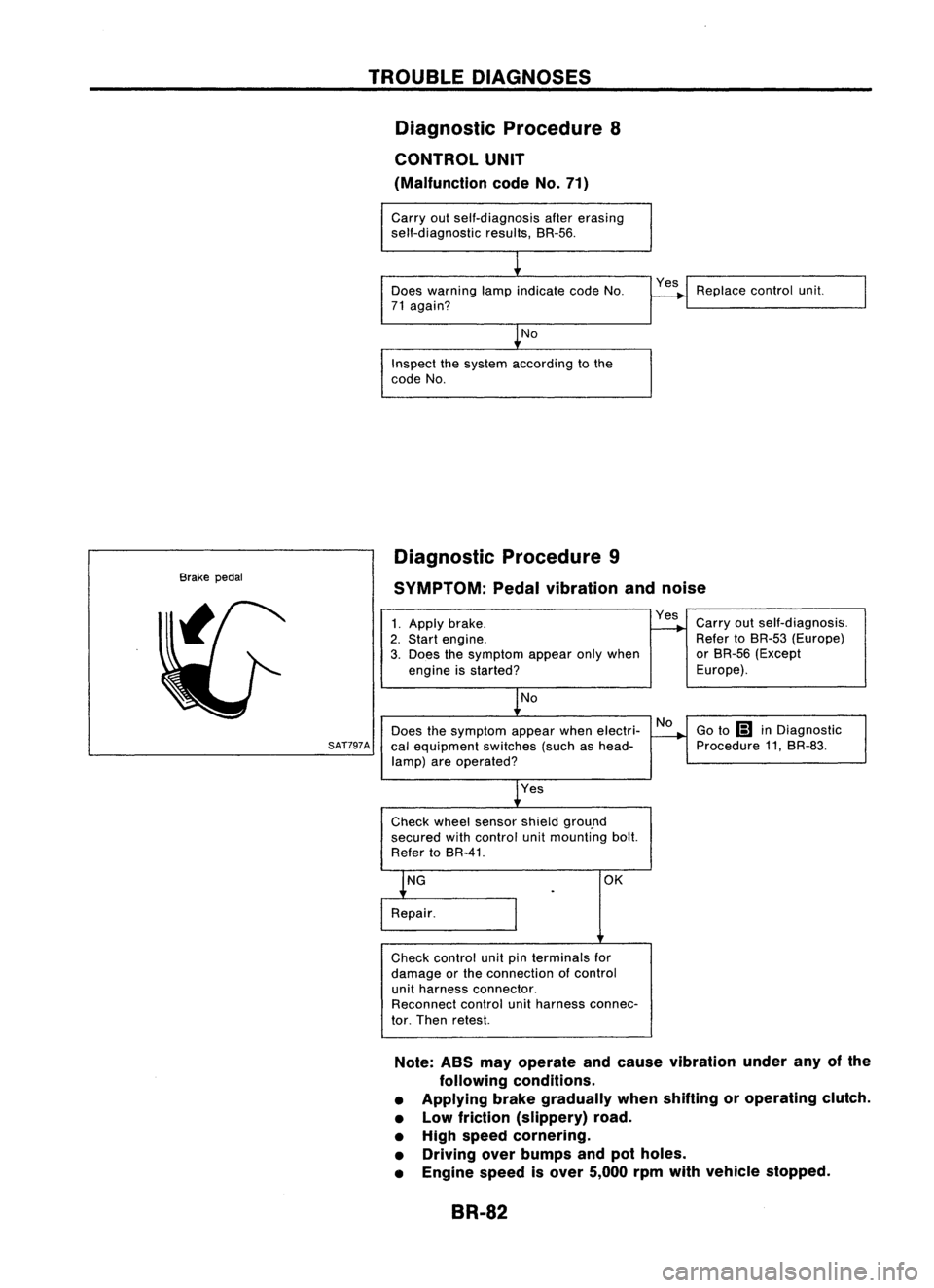
Brake pedal Diagnostic
Procedure9
SYMPTOM: Pedalvibration andnoise
No
Does thesymptom appearwhenelectri-
SAT797A
calequipment switches(suchashead-
lamp) areoperated?
1.
Apply brake.
2. Start engine.
3. Does thesymptom appearonlywhen
engine isstarted?
No
Yes
Check wheelsensor shieldgrou.nd
secured withcontrol unitmounting bolt.
Refer toBR-41. Yes
Carryoutself-diagnosis.
Refer toBR-53 (Europe)
or BR-56 (Except
Europe).
Go to
Ii1
inDiagnostic
Procedure 11,BR-83.
OK
Check control unitpinterminals for
damage orthe connection ofcontrol
unit harness connector.
Reconnect controlunitharness connec-
tor. Then retest.
Note: ABSmayoperate andcause vibration underanyofthe
following conditions.
• Applying brakegradually whenshifting oroperating clutch.
• Low friction (slippery) road.
• High speed cornering.
• Driving overbumps andpotholes.
• Engine speedisover 5,000 rpmwith vehicle stopped.
BR-82
Page 363 of 1701
INSPECTIONANDADJUSTMENT
Pedal stopper
Dash lower
panel (except
CD20 engine //
model)
/L
Floor car-pet
L
Dash reinforcement panel
(CD20 engine model)
Adjusting
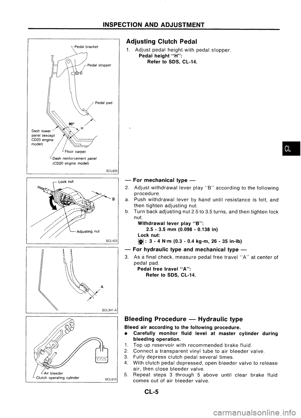
ClutchPedal
1. Adjust pedalheight withpedal stopper.
Pedal height
"H":
Refer to
50S,
CL-14.
•
SCL625
SCL423 -
For mechanical type-
2. Adjust withdrawal leverplay"8"according tothe following
procedure_
a. Push withdrawal leverbyhand untilresistance isfelt, and
then tighten adjusting nut.
b. Turn backadjusting nut2.5to3.5 turns, andthen tighten lock
nut.
Withdrawal leverplay
"B":
2.5 -3.5 mm (0.098 -0.138 in)
lock nut:
~: 3-
4 N'm (0.3-0.4 kg-m, 26-35 in-Ib)
- For hydraulic typeandmechanical type-
3. Asafinal check, measure pedalfreetravel "A"atcenter of
pedal pad.
Pedal freetravel
"A":
Refer to
50S,
CL-14.
B
Bleeding Procedure -Hydraulic type
Bleed airaccording tothe following procedure.
• Carefully monitorfluidlevel atmaster cylinder during
bleeding operation.
1. Top upreservoir withrecommended brakefluid.
2. Connect atransparent vinyltubetoair bleeder valve.
3. Fully depress clutchpedalseveral times.
4. With clutch pedaldepressed, openbleeder valvetorelease
air, then close bleeder valve.
5. Repeat steps3through 5above untilclear brake fluid
SCL613
comesoutofair bleeder valve.
SCL341-A
Adjusting
nut
Lock
nut
CL-5
Page 372 of 1701
SERVICEDATAANDSPECIFICATIONS (SOS)
Inspection andAdjustment
CLUTCH PEDAL
Unit:mm(in)
Except forCD20 engine models
CD20engine models
Applied model
RHOLHD
RHO LHD
Pedal height "H"
159-169 (6.26 -6.65)'1 153-163 (6.02 -6.42)*2 156-166 (6.14 -6.54)'1
149-159 (5.87 -6.26)'2
Pedal freetravel "A"
11-15 (0.43 -0.59)
9-16 (0.35 -0.63)
(at pedal pad)
Withdrawal leverplay"8" 2.5-3.5 (0.098 -0.138)
-
'1: Measured fromsurface ofdash reinforcement paneltosurface ofpedal pad.
'2: Measured fromsurface ofdash lower paneltosurface ofpedal pad.
CLUTCH DISC
Unit:mm(in)
Disc model
180190
I
200
215
Wear limitoffacing surface torivet head
0.3(0.012)
Runout limitoffacing 1.0(0.039)
Distance ofrunout checkpoint(from hub
85(3.35) 90(3.54)
I
95
(3.74) 102.5(4.04)
center)
Maximum backlashofspline (atouter edgeof
0.7(0.028) 0.8(0.031)
0.9(0.035)
disc)
CLUTCH COVER
Cover model
Uneven limitofdiaphragm springtoeheight 180
1.0 (0.039)
CL-14 190
I
200
0.7 (0.028)
I
Unit:
mm(in)
215
Page 397 of 1701
SEL711EBATTERY
CAUTION:
• If
itbecomes necessary tostart theengine withabooster
battery andjumper cables, usea12-volt booster battery.
• After connecting batterycables, ensurethatthey aretightly
clamped tobattery terminals forgood contact.
• Never adddistilled waterthrough thehole used tocheck
specific gravity.
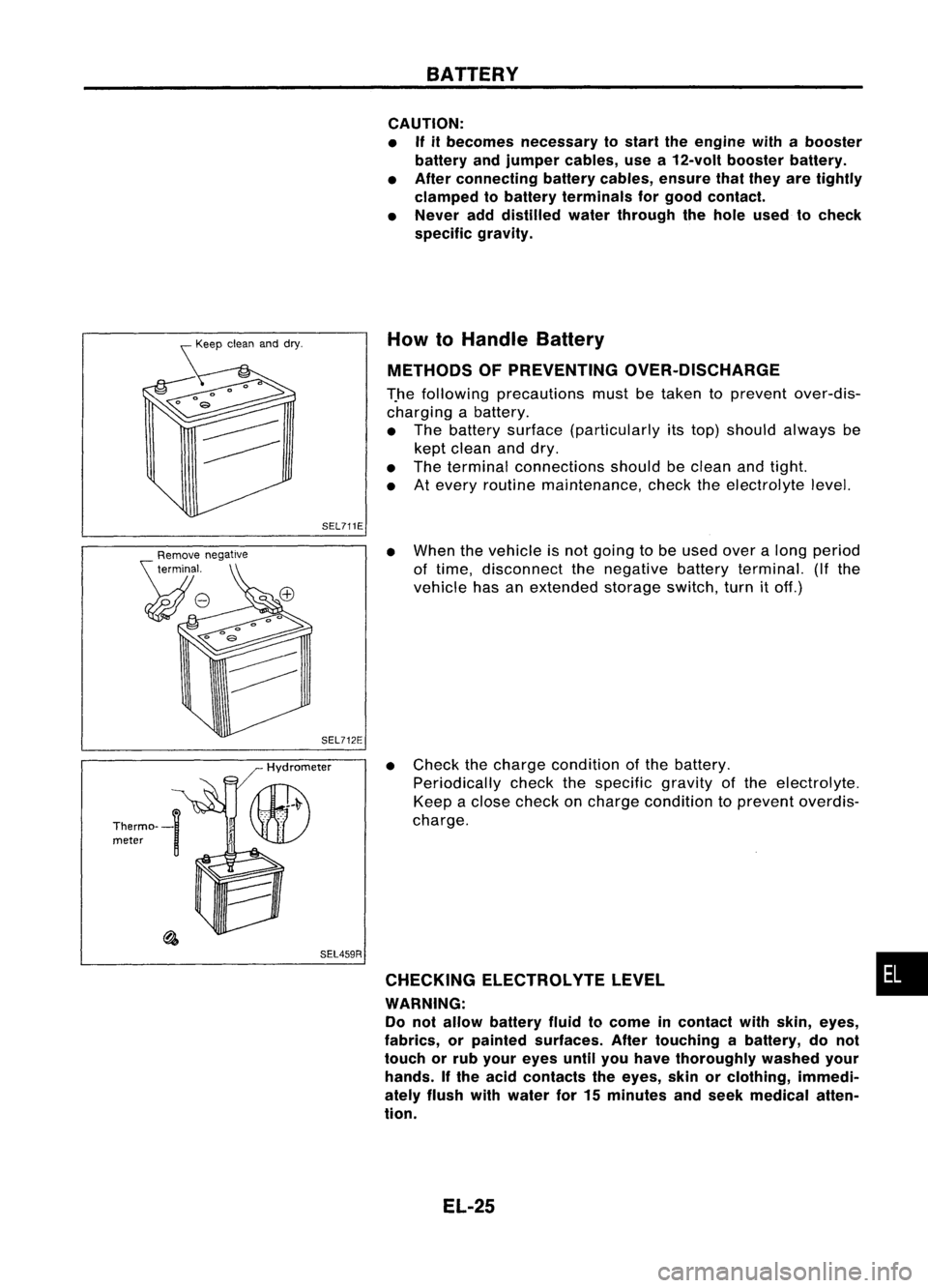
How toHandle Battery
METHODS OFPREVENTING OVER-DISCHARGE
T.he following precautions mustbetaken toprevent over-dis-
charging abattery.
• The battery surface (particularly itstop) should always be
kept clean anddry.
• The terminal connections shouldbeclean andtight.
• Atevery routine maintenance, checktheelectrolyte level.
SEL459R
•
When thevehicle isnot going tobe used overalong period
of time, disconnect thenegative batteryterminal. (Ifthe
vehicle hasanextended storageswitch,turnitoff.)
• Check thecharge condition ofthe battery.
Periodically checkthespecific gravityofthe electrolyte.
Keep aclose check oncharge condition toprevent overdis-
charge.
CHECKING ELECTROLVTELEVEL •
WARNING: Do not allow battery fluidtocome incontact withskin, eyes,
fabrics, orpainted surfaces. Aftertouching abattery, donot
touch orrub your eyes untilyouhave thoroughly washedyour
hands. Ifthe acid contacts theeyes, skinorclothing, immedi-
ately flush withwater for15minutes andseek medical atten-
tion.
EL-25
Page 404 of 1701
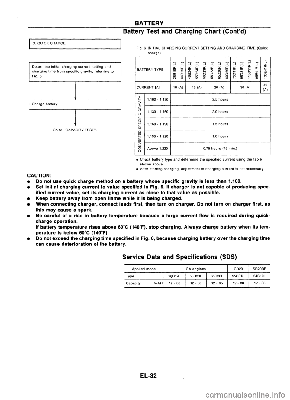
I
C: QUICK CHARGE
Determine initialcharging currentsettingand
charging timefrom specific gravity,referring to
Fig. 6.
I
Charge battery.
Goto"CAPACITY TEST".
BATTERY
Battery TestandCharging Chart(Cont'd)
Fig. 6INITIAL CHARGING CURRENTSETTINGANDCHARGING TIME(Quick
charge)
:::J:::J:::J:::J :::J:::J:::J
d dd
:::J
:::J :::J
~ ~
SA TTERY TYPE
~
~ ~~~~ ~a: a:a:
;;:;
~
~
0>
0>
""
""
C')
C')
CDCD
;;:;
;;:;
~
co co
C\I
N
C\I
N
C\I
N
Cl
W
D:l D:l
ClCl ClCl ClCl
L()
W
0
to
""
CD
L()
0
L()
L()
0
L()
L()
;:
L()
~
N
C')
""
L()
L()L()
CD
to
t-
O>
0>
CURRENT [A]10(A) 15(A) 20(A) 30(A) 40
(A)
>-
I-
1.100 -1.130 2.5
hours
:>
a:
(!J 1.130 -1.160 2.0
hours
0
u::
U
w
1.160 -1.190 1.5hours
0-
w
Cl
w
1.190 -1.220 1.0hours
I-
a:
w
>
z
0
Above 1.220 0.75
hours (45min.)
0
• Check battery typeanddetermine thespecified currentusingthetable
shown above.
• After starting charging, adjustment ofcharging currentisnot necessary.
CAUTION: • Donot use quick charge method onabattery whosespecific gravityisless than 1.100.
• Set initial charging currenttovalue specified inFig. 6.Ifcharger isnot capable ofproducing spec-
ified current value,setitscharging currentasclose tothat value aspossible.
• Keep battery awayfromopen flame whileitis being charged.
• When connecting charger,connectleadsfirst,thenturnoncharger. Donot turn oncharger first,as
this may cause aspark.
• Becareful ofarise inbattery temperature becausealarge current flowisrequired duringquick-
charge operation.
If
battery temperature risesabove 60°C(140°F), stopcharging. Alwayschargebatterywhenitstem-
perature isbelow 60°C(140°F).
• Donot exceed thecharging timespecified inFig. 6,because charging batteryoverthecharging time
can cause deterioration ofthe battery.
Service DataandSpecifications (SOS)
Applied model GA
engines CD20SR20DE
Type 26S19L
55D23L65D26L 95D31L
34S19L
Capacity V-AH
12-30 12
-60 12-65 12-80 12
-33
EL-32