Page 190 of 1701

__________ BODYALIGNMENT _
_ PRECAUTIONS _
Description PrecautionsForHandling HighStrength Steel
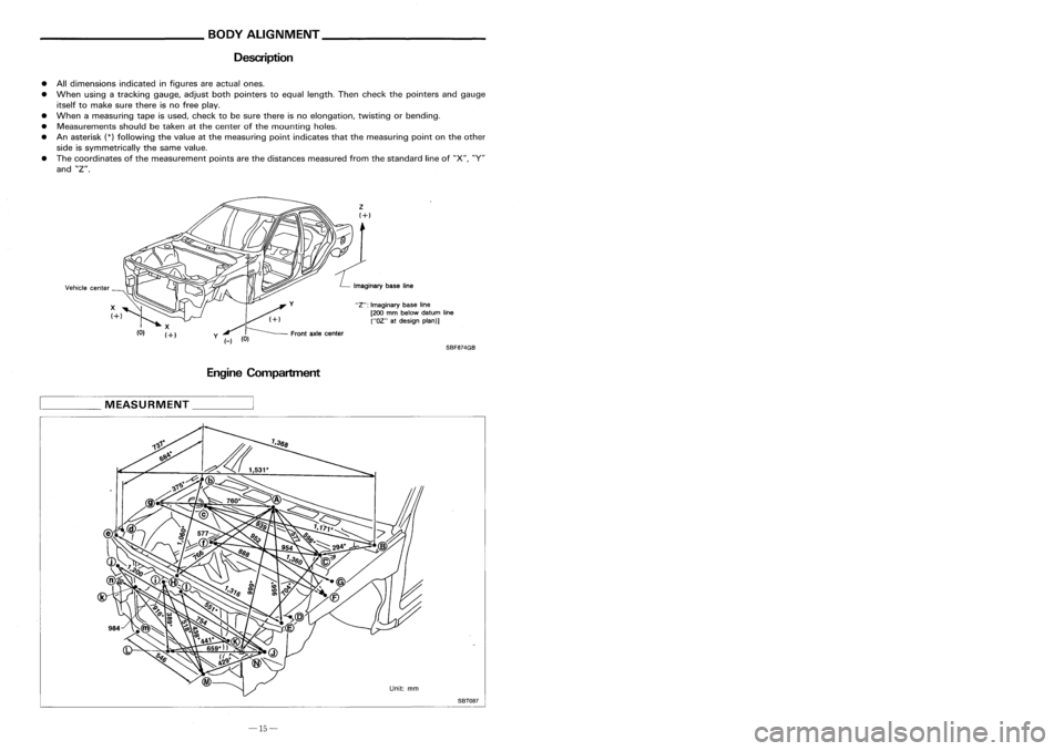
• Alldimensions indicatedinfigures areactual ones.
• When usingatracking gauge,adjustbothpointers toequal length. Thencheck thepointers andgauge
itself tomake surethere isno free play.
• When ameasuring tapeisused, check tobe sure there isno elongation, twistingorbending.
• Measurements shouldbetaken atthe center ofthe mounting holes.
• Anasterisk
(*)
following thevalue atthe measuring pointindicates thatthemeasuring pointonthe other
side issymmetrically thesame value.
• The coordinates ofthe measurement pointsarethe distances measured fromthestandard lineof"X", "V"
and "Z".
EngineCompartment
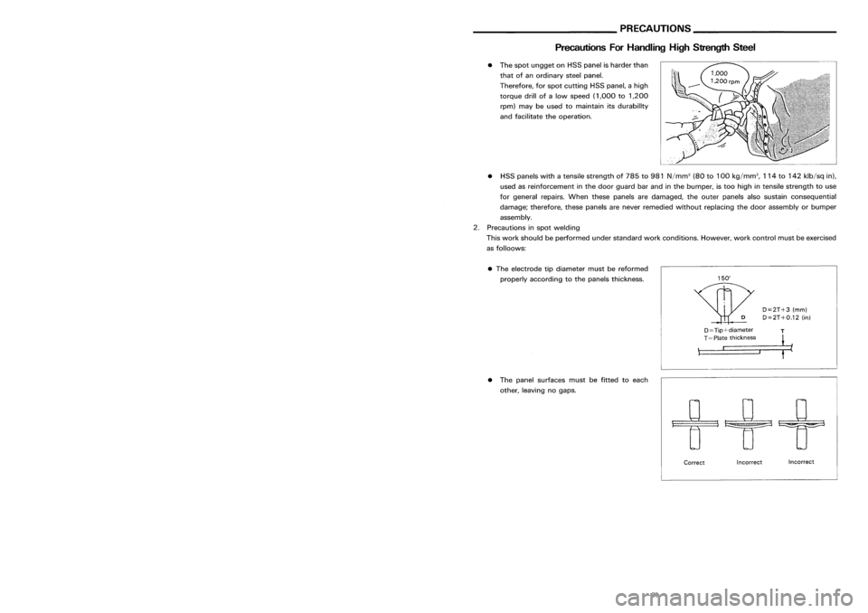
D=2T+3(mm)
D=2T+O.12 (in)
•
The electrode tipdiameter mustbereformed
properly according tothe panels thickness.
•
The spot ungget onHSS panel isharder than
that ofan ordinary steelpanel.
Therefore, forspot cutting HSSpanel, ahigh
torque drillofalow speed (1,000 to1,200
rpm) maybeused tomaintain itsdurability
and facilitate theoperation.
• HSS panels withatensile strength of785 to981 N/mm
2
(80to100 kg/mm
2,
114to142 klb/sq in),
used asreinforcement inthe door guard barand inthe bumper, istoo high intensile strength touse
for general repairs.Whenthesepanels aredamaged, theouter panels alsosustain consequential
damage; therefore, thesepanels arenever remedied withoutreplacing thedoor assembly orbumper
assembly.
2. Precautions inspot welding
This work should beperformed understandard workconditions. However,workcontrol mustbeexercised
as folloows:
SBF8?4GB
"Z":
Imaginary baseline
[200 mmbelow datum line
("OZ" atdesign plan)]
Front axlecenter
/
y (_)
(0)
Incorrect
Incorrect
Correct
D==Tip+diameter
T
,::=T====p=la::t_e=-=-_t_h=i_C=k=_n=_e_s=s= __,-- ~
• The panel surfaces mustbefitted toeach
other, leaving nogaps.
____
MEASURMENT _
SBT08?
-15- -30-
Page 205 of 1701

__________ BODYALIGNMENT _
_ PRECAUTIONS _
Description PrecautionsForHandling HighStrength Steel
• Alldimensions indicatedinfigures areactual ones.
• When usingatracking gauge,adjustbothpointers toequal length. Thencheck thepointers andgauge
itself tomake surethere isno free play.
• When ameasuring tapeisused, check tobe sure there isno elongation, twistingorbending.
• Measurements shouldbetaken atthe center ofthe mounting holes.
• Anasterisk
(*)
following thevalue atthe measuring pointindicates thatthemeasuring pointonthe other
side issymmetrically thesame value.
• The coordinates ofthe measurement pointsarethe distances measured fromthestandard lineof"X", "V"
and "Z".
EngineCompartment
D=2T+3(mm)
D=2T+O.12 (in)
•
The electrode tipdiameter mustbereformed
properly according tothe panels thickness.
•
The spot ungget onHSS panel isharder than
that ofan ordinary steelpanel.
Therefore, forspot cutting HSSpanel, ahigh
torque drillofalow speed (1,000 to1,200
rpm) maybeused tomaintain itsdurability
and facilitate theoperation.
• HSS panels withatensile strength of785 to981 N/mm
2
(80to100 kg/mm
2,
114to142 klb/sq in),
used asreinforcement inthe door guard barand inthe bumper, istoo high intensile strength touse
for general repairs.Whenthesepanels aredamaged, theouter panels alsosustain consequential
damage; therefore, thesepanels arenever remedied withoutreplacing thedoor assembly orbumper
assembly.
2. Precautions inspot welding
This work should beperformed understandard workconditions. However,workcontrol mustbeexercised
as folloows:
SBF8?4GB
"Z":
Imaginary baseline
[200 mmbelow datum line
("OZ" atdesign plan)]
Front axlecenter
/
y (_)
(0)
Incorrect
Incorrect
Correct
D==Tip+diameter
T
,::=T====p=la::t_e=-=-_t_h=i_C=k=_n=_e_s=s= __,-- ~
• The panel surfaces mustbefitted toeach
other, leaving nogaps.
____
MEASURMENT _
SBT08?
-15- -30-
Page 225 of 1701

BODYEND
Body Front End
• When removing orinstalling hood,placeacloth orother padding onhood. Thisprevents vehiclebody
from being scratched.
• Bumper fasciaismade ofplastic. Donot use excessive forceandbesure tokeep oilaway fromit.
• Hood adjustment: Adjustathinge portion.
• Hood lockadjustment: Afteradjusting, checkhoodlockcontrol operation. Applyacoat ofgrease to
hood locks engaging mechanism.
• Hood opener: Donot attempt tobend cable forcibly. Doingsoincreases effortrequired tounlock
hood.
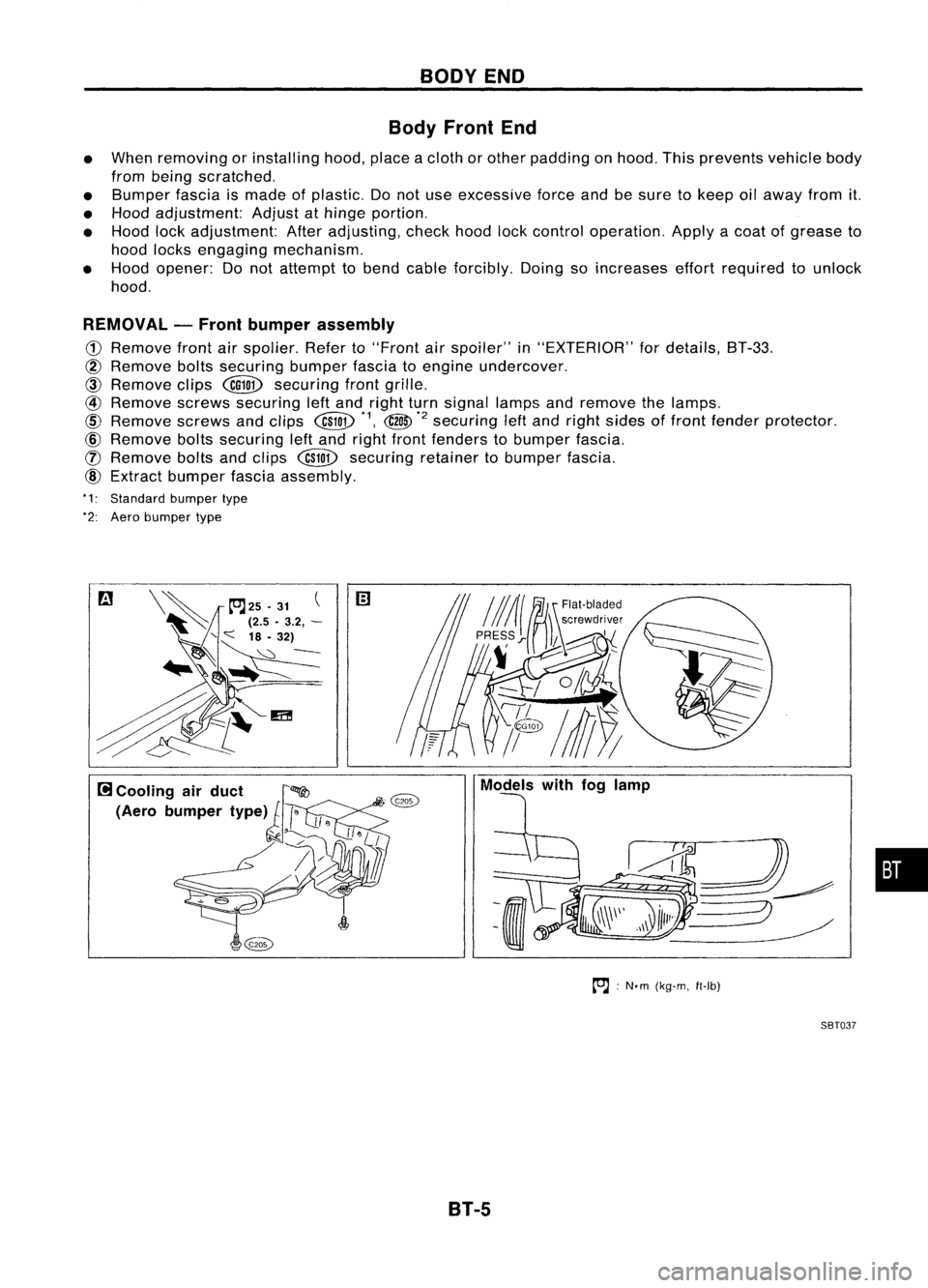
REMOVAL -Front bumper assembly
CD
Remove frontairspolier. Referto"Front
air
spoiler" in"EXTERIOR" fordetails, BT-33.
@
Remove boltssecuring bumperfasciatoengine undercover.
CID
Remove clips
@QD
securing frontgrille.
@
Remove screwssecuring leftand right turnsignal lampsandremove thelamps.
@
Remove screwsandclips
@W
*1,
@
*2
securing
leftand right sides offront fender protector.
@)
Remove boltssecuring leftand right front fenders tobumper fascia.
([) Remove boltsandclips
@W
securing retainertobumper fascia.
@)
Extract bumper fasciaassembly.
*1: Standard bumpertype
*2: Aero bumper type
to.J:
N'm (kg-m, ft-Ib)
SBT037
B1-5
•
Page 267 of 1701
BODYALIGNMENT
• Alldimensions indicatedinfigures areactual ones.
• When usingatracking gauge,adjustbothpointers toequal length. Thencheck thepointers and
gauge itselftomake surethere isno free play.
• When ameasuring tapeisused, check tobe sure there isno elongation, twistingorbending.
• Measurements shouldbetaken atthe center ofthe mounting holes.
• Anasterisk
(*)
following thevalue atthe measuring pointindicates thatthemeasuring pointonthe
other sideissymmetrically thesame value.
• The coordinates ofthe measurement pointsarethedistances measured fromthestandard lineof
"X", "Y"andHZ".
Frontaxlecenter
I
v
~
/
y
H
(0)
2
(+)
~r
L"oo"
b.~
Ii"'
"2": Imaginary baseline
[200 mmbelow datum line
("02" atdesign plan)]
MEASUREMENT
SBF874GB
Engine Compartment
SBT087
8T-47
•
Page 275 of 1701

CHECKANDADJUSTMENT
OK
MINMax.
line
Min. line
SBR418C
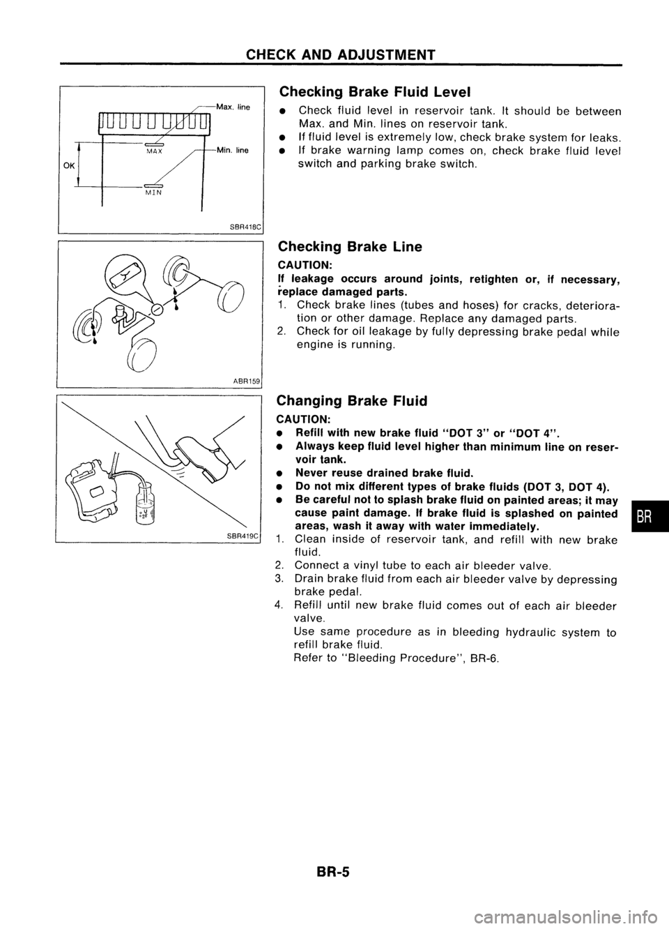
Checking
BrakeFluidLevel
• Check fluidlevel inreservoir tank.Itshould bebetween
Max. andMin. lines onreservoir tank.
• Iffluid level isextremely low,check brakesystem forleaks.
• Ifbrake warning lampcomes on,check brakefluidlevel
switch andparking brakeswitch.
ABR159
SBR419C
Checking
BrakeLine
CAUTION: If leakage occursaround joints,retighten or,ifnecessary,
replace damaged parts.
1. Check brakelines(tubes andhoses) forcracks, deteriora-
tion orother damage. Replaceanydamaged parts.
2. Check foroilleakage byfully depressing brakepedalwhile
engine isrunning.
Changing BrakeFluid
CAUTION:
• Refill withnewbrake fluid"DOT 3"or"DOT 4".
• Always keepfluidlevel higher thanminimum lineonreser-
voir tank.
• Never reusedrained brakefluid.
• Donot mix different typesofbrake fluids(DOT3,DOT 4).
• Becareful nottosplash brakefluidonpainted areas;itmay •
cause paintdamage. Ifbrake fluidissplashed onpainted :•
areas, washitaway withwater immediately.
1. Clean inside ofreservoir tank,andrefill withnewbrake
fluid.
2. Connect avinyl tubetoeach airbleeder valve.
3. Drain brake fluidfrom each airbleeder valvebydepressing
brake pedal.
4. Refill untilnewbrake fluidcomes outofeach airbleeder
valve.
Use same procedure asinbleeding hydraulic systemto
refill brake fluid.
Refer to"Bleeding Procedure", BR-6.
BR-5
Page 281 of 1701
SEC.465
iii :
N'm (kg-m, in-Ib)
~ :N'm (kg-m, ft-Ib)
BRAKE
PEDALANDBRACKET
Removal andInstallation
Sloplamp sWitch
SBR205D
o
Inspection
Check brakepedalforfollowing items:
• Brake pedalbend
• Clevis pindeformation
• Crack ofany welded portion
• Crack ordeformation ofclevis pinstopper
•
SBR997
Adjustment
Check brakepedalfreeheight fromdash reinforcement panel
(RHD) anddash lower panel (LHD). Adjust ifnecessary.
H: Freeheight
Refer to
50S
(BR-SS).
0: Depressed height
Refer to
50S
(BR-SS).
Under forceof
490
N
(50
kg,
110
Ib)
with engine running
1. Loosen locknutand adjust pedalfreeheight byturning
brake booster inputrod.Then tighten locknut.
2. Check pedalfreeplay.
Make surethatstop lamps gooff when pedal isreleased.
3. Check brakepedal's depressed heightwhileengine isrun-
ning. If lower thanspecification, checkforleaks, airinsystem or
damage tocomponents (mastercylinder, wheelcylinder,
etc.). Then make necessary repairs.
SBR034D BR-11
Page 285 of 1701
OKNGBRAKE
BOOSTER
On-vehicle Service
OPERATING CHECK
• Depress brakepedalseveral timeswithengine off.After
exhausting vacuum,makesurethere isno change inpedal
stroke.
• Depress brakepedal, thenstart engine. Ifpedal goesdown
slightly, operation isnormal.
AIRTIGHT CHECK
• Start engine, andstop itafter oneortwo minutes. Depress
SBR002A
brakepedalseveral timesslowly. Booster isairtight ifpedal
stroke isless each time.
• Depress brakepedalwhileengine isrunning, andstop
engine withpedal depressed. Thepedal stroke should not
change afterholding pedaldownfor
30seconds.
SBR365AA Removal
CAUTION:
• Becareful nottosplash brakefluidonpainted areas;itmay
cause paintdamage. Ifbrake fluidissplashed onpainted
areas, washitaway withwater immediately.
• Be careful nottodeform orbend brake pipes, during
removal ofbooster.
SEC.
465.470
BR-15Gasket
~ :N.m (kg-m. ft-Ib)
SBR223BB
•
Page 288 of 1701
VACUUMHOSE
Inspection (Cont'd)
CHECK VALVE
Check vacuum withavacuum pump.
~
Booster side
SBR943A
Connect
to
booster side
Connect to
engine side Vacuum
shouldexist.
Vacuum shouldnotexist.
Engine side
VACUUM WARNING SWITCH(Dieselenginemodels)
Test continuity throughvacuum warning switchwithanohmme-
ter and vacuum pump.
Booster
side
Arrowindicates
engine side
SBR826B
SBR007A
Vacuum
condition
Less than26.7kPa
(267 mbar, 200mmHg, 7.87inHg)
33.3 kPa
(333 mbar, 250mmHg, 9.84inHg) or
more Continuity
Yes
No
VACUUM PUMP
1. Install vacuum gauge.
2. Run engine at1,000 rpmormore.
3. Check vacuum.
Specified vacuum:
86.6 kPa
(8~6
mbar, 650mmHg, 25.59inHg) ormore
BR-18