Page 634 of 1701
Ii
1
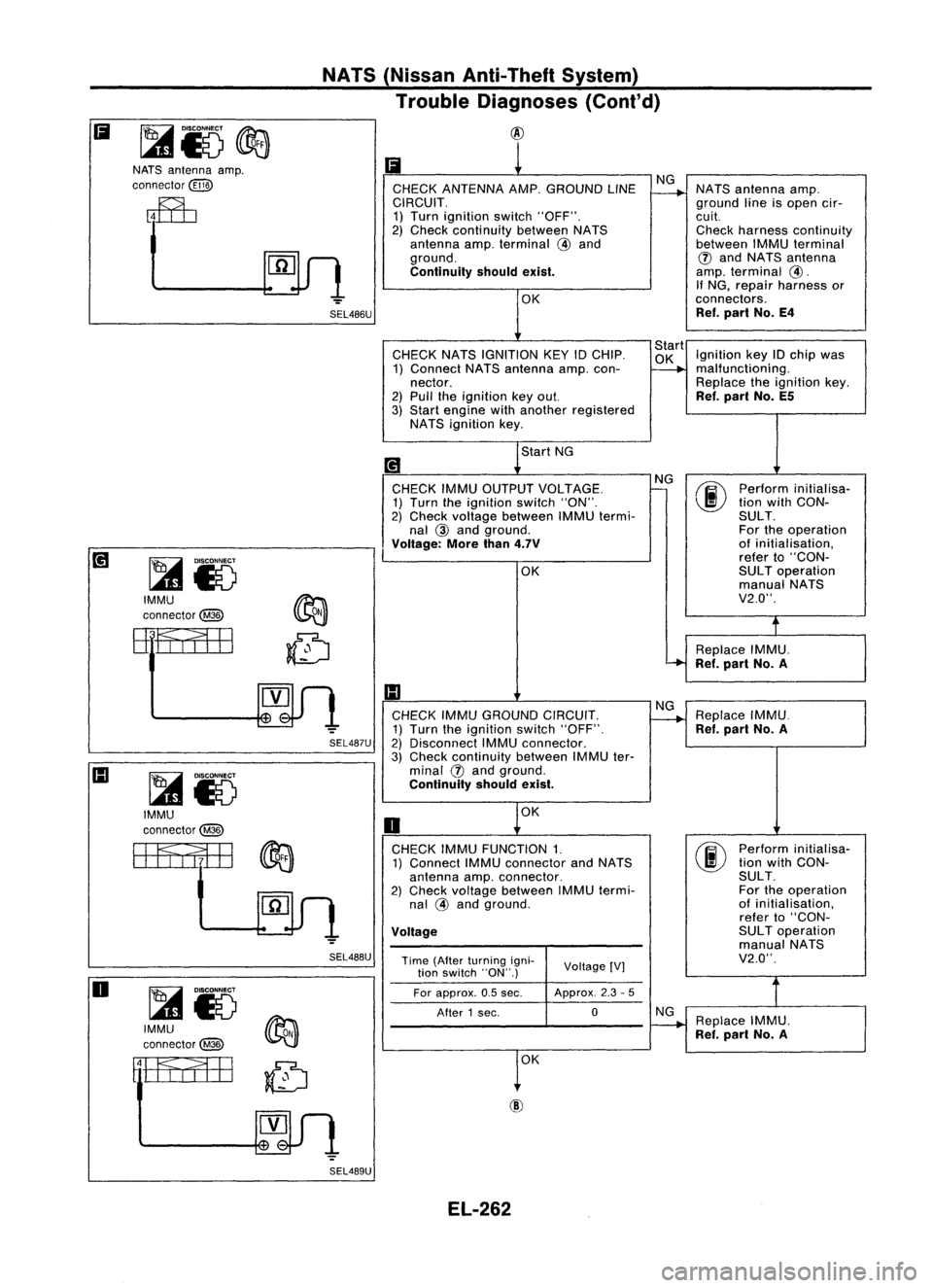
CHECK ANTENNA AMP.GROUND LINENG
~
NATS
antenna amp.
CIRCUIT. groundlineisopen cir-
1) Turn ignition switch"OFF". cuit.
2) Check continuity betweenNATS Checkharness continuity
antenna amp.terminal
@
and betweenIMMUterminal
ground.
(J)
and NATS antenna
Continuity shouldexist.
amp.
terminal
@.
If NG, repair harness or
OK connectors.
Ref. part No.E4
CHECK NATSIGNITION KEY
10
CHIP. Start
Ignition key
10
chip was
1) Connect NATSantenna amp.con-
~
malfunction
i
ng.
nector. Replacetheignition key.
2) Pull theignition keyout.
Ref.
part No.E5
3) Start engine withanother registered
NATS ignition key.
Start NG
[!1
NG
00
Perform
initialisa-
CHECK IMMUOUTPUT VOLTAGE.
-
1) Turn theignition switch"ON". tion
with CON-
2) Check voltage between IMMUtermi- SULT.
nal
@
and ground. Fortheoperation
Voltage: Morethan4.7V
of
initialisation,
refer to"CON-
OK SUL
Toperation
manual NATS
V2.0".
t
Replace IMMU.
'-+
Ref.part No.A
1:1
CHECK IMMUGROUND CIRCUIT. NG
Replace IMMU.
~
1) Turn theignition switch"OFF".
Ref.part No.A
2) Disconnect IMMUconnector.
3) Check continuity betweenIMMUter-
minal
(J)
and ground.
Continuity shouldexist.
OK
0
CHECK IMMUFUNCTION 1.
00
Perform
initialisa-
1) Connect IMMUconnector andNATS tion
with CON-
antenna amp.connector. SULT.
2) Check voltage between IMMUtermi- For
theoperation
nal
@
and ground. of
initialisation,
refer to"CON-
Voltage
SUL
Toperation
manual NATS
Time (After turning igni-
VoltageIV] V2.0".
tion switch "ON".)
For approx. 0.5sec. Approx.
2.3-5
After 1sec. 0
NG
Replace IMMU.
~
Ref.part No.A
1
0K
SEL486U
SEL488U
SEL487U
NATS
(Nissan Anti-Theft System)
Trouble Diagnoses (Cont'd)
@
~i5
IMMU
connector@
~i5
IMMU
connector@
ffitflfEB
NATS
antenna amp.
connector
@ID
~i5
IMMU
connector@
rtfa;EB
Ii
o
SEL489UEL-262
Page 635 of 1701
SEL490U
IMMU
connector@
NATS
(Nissan Anti-Theft System)
Trouble Diagnoses (Cont'd)
CID
II
1
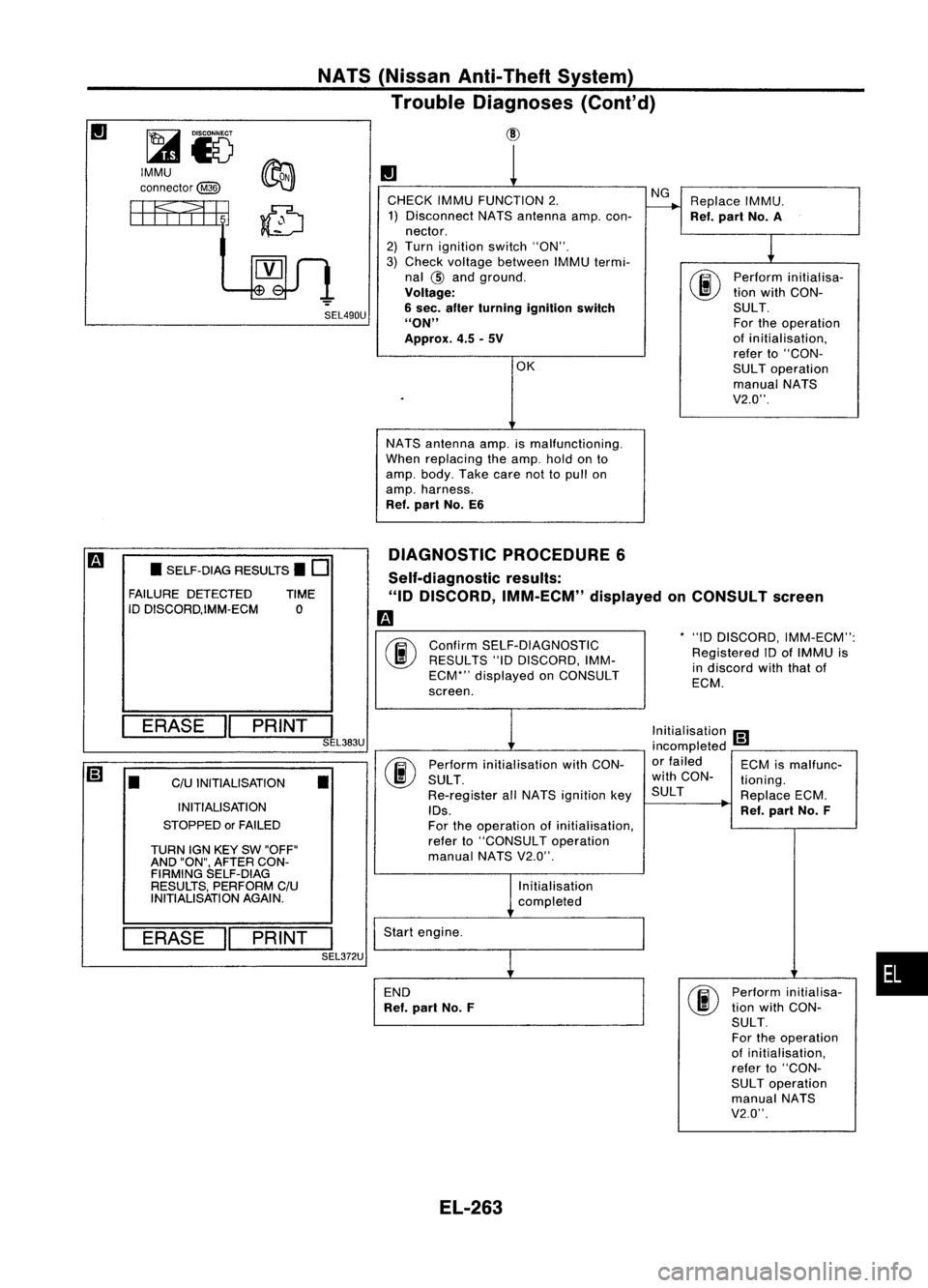
CHECK IMMUFUNCTION 2. NG
Replace IMMU.
1) Disconnect NATSantenna amp.con-
r---+
Ref.part No.A
nector.
1
2)
Turn ignition switch"ON".
3) Check voltage between IMMUtermi-
nal
@
and ground.
00
Perform
initialisa-
Voltage: tion
with CON-
6 sec. after turning ignition switch SULT.
"ON" Fortheoperation
Approx. 4.5-5V of
initialisation,
refer to"CON-
OK SULToperation
manual NATS
V2.0".
NATS antenna amp.ismalfunctioning.
When replacing theamp. holdonto
amp. body. Takecarenottopull on
amp. harness.
Ref. part No.E6
DIAGNOSTIC PROCEDURE6
*"10 DISCORD, IMM-ECM":
Registered IDofIMMU is
in discord withthatof
ECM.
Confirm
SELF-DIAGNOSTIC
RESULTS "10DISCORD, IMM-
ECM*" displayed onCONSULT
screen.
Self-diagnostic
results:
"ID DISCORD, IMM-ECM" displayedonCONSULT screen
m
00
•
SELF-DIAG RESULTS.
0
FAILURE DETECTED TIME
ID DISCORD,IMM-ECM 0
ERASE
II
PRINT
I
SEL383U
[;]
•
C/U
INITIALISATION
•
INITIALISATION
STOPPED orFAILED
TURN IGNKEY SW"OFF"
AND "ON", AFTER CON-
FIRMING SELF-DIAG
RESULTS, PERFORM C/U
INITIALISATION AGAIN.
ERASE
II
PRINT
I
SEL372U Perform
initialisation withCON-
SULT .
Re-register allNATS ignition key
IDs.
For theoperation ofinitialisation,
refer to"CONSULT operation
manual NATSV2.0".
Initialisation
completed
Start engine.
END
Ref. part No.F Initialisation
[;]
incompleted -
or failed ECMismalfunc-
with CON- tioning.
SUL T ReplaceECM.
Ref. part No.F
Perform initialisa-
tion with CON-
SULT.
For theoperation
of initialisation,
refer to"CON-
SUL Toperation
manual NATS
V2.0".
•
EL-263
Page 636 of 1701
Self-diagnosticresults:
"MINGLE NOISE"displayed onCONSULT screen
m
T
Confirm SELF-DIAGNOSTIC RESULTS"MINGLENOISE"dis-
~ played onCONSULT screen.
NATS
(Nissan Anti-Theft System)
Trouble Diagnoses (Cont'd)
DIAGNOSTIC PROCEDURE 7
• SELF.DIAG RESULTS.
0
FAILURE DETECTED TIME
MINGLE NOISE 0
ERASE
II
PRINT
I
Turnofforremove anypossible noisesources.
SEL384U
• SELF.DIAG RESULTS.
0
FAILURE DETECTED TIME
MINGLE NOISE 0 Touch
"ERASE" onCONSULT SELF-DIAGNOSTIC RESULTS
screen.
ER~I PRINT
I
SEL385U
Start
engine.
OK
END
NG
DIAGNOSTIC PROCEDURE8
"NATS SECURITY IND.DOES NOTLIGHT UP"
m
o
UP
SIDE I~
....
EE3J
7.5A
SEL491U
Check
fuse(7.5A) inthe fuse box.
OK
NATS INITIALISATION
1) Fix the 7.5A fuseshown left
m.
2) Perform initialisation with
CONSULT.
For theoperation of
initialisation, referto"CON-
SUL Toperation manualNATS
V2.0".
NG
Replace fuse.
Turn ignition switch"OFF".
Start engine andturn ignition switch
"OFF".
Check NATSsecurity indoblinking.
OK
END
NG
EL-264
Page 684 of 1701
PRECAUTIONSANDPREPARATION
Precautions
• When installing rubberparts,finaltightening mustbecar-
ried outunder unladen condition* withtires onground.
*: Fuel, radiator coolantandengine oilfull. Spare tire,
jack,
hand tools andmats indesignated positions.
• After installing removedsuspension parts,check wheel
alignment andadjust ifnecessary.
• Use flare nutwrench whenremoving orinstalling brake
tubes.
• Always torquebrakelineswhen installing.
Tool number
Tool name
SBR820B
Special Service Tools
Description
HT72520000
Ball joint remover Removing
tie-rodouterendandlower ball
joint
NT146
HT71780000
Spring compressor
ST35652000
Strut attachment
NT144
Removing
andinstalling coilspring
Fixing strutassembly
NT145
GG94310000
Flare nuttorque wrench
KV38106700
KV381 06800
Differential sideoilseal
protector
NT406
NT147
FA-2
Removing
andinstalling brakepiping
a:
10mm (0.39 in)
Installing driveshaft
LH: KV38106700
RH: KV38106800
Page 688 of 1701
ON-VEHICLESERVICE
Front Wheel Alignment
Before checking frontwheel alignment, besure tomake apre-
liminary inspection (Unladen*).
*: Fuel, radiator coolantandengine oilfull. Spare tire,jack,
hand tools andmats indesignated positions.
SFA575B PRELIMINARY INSPECTION
1. Check tiresforwear andimproper inflation.
2. Check wheelrunout.
Wheel runout:
Refer toSOS (FA-30).
3. Check frontwheel bearings forlooseness.
4. Check frontsuspension forlooseness.
5. Check steering linkageforlooseness.
6. Check thatstruts workproperly.
7. Check vehicle posture (Unladen).
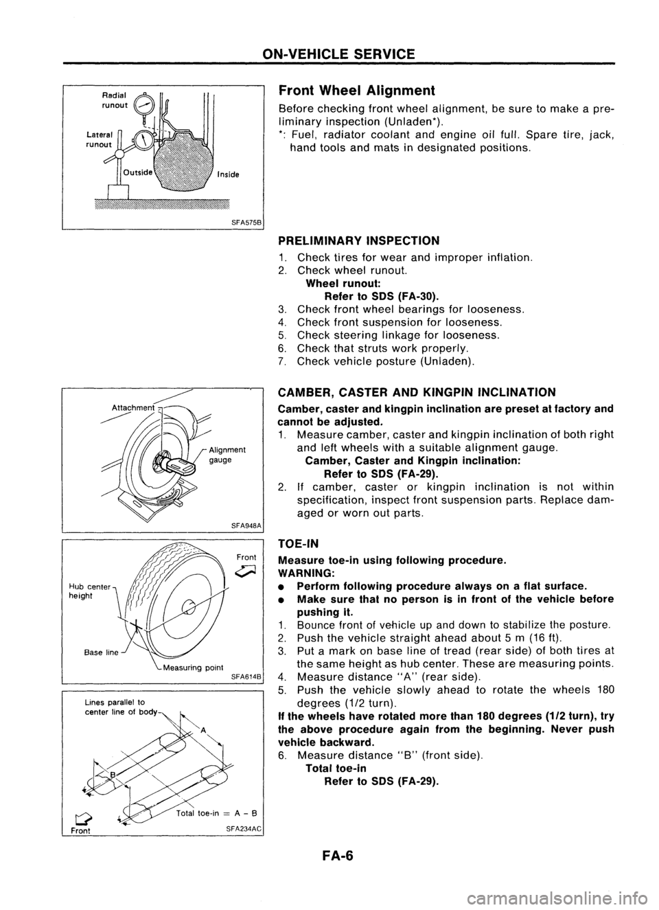
TOE-IN Measure toe-inusingfollowing procedure.
WARNING:
• Perform following procedure alwaysonaflat surface.
• Make surethatnoperson isin front ofthe vehicle before
pushing it.
1. Bounce frontofvehicle upand down tostabilize theposture.
2. Push thevehicle straight aheadabout5m (16 ft).
3. Put amark onbase lineoftread (rearside) ofboth tires at
the same height ashub center. Thesearemeasuring points.
4. Measure distance"A"(rear side).
5. Push thevehicle slowlyaheadtorotate thewheels 180
degrees (1/2turn).
If the wheels haverotated morethan180degrees
(112
turn), try
the above procedure againfromthebeginning. Neverpush
vehicle backward.
6. Measure distance"B"(front side).
Total toe-in
Refer toSOS (FA-29).
CAMBER,
CASTERANDKINGPIN INCLINATION
Camber, casterandkingpin inclination arepreset atfactory and
cannot beadjusted.
1. Measure camber,casterandkingpin inclination ofboth right
and leftwheels withasuitable alignment gauge.
Camber, CasterandKingpin inclination:
Refer toSOS (FA-29).
2. Ifcamber, casterorkingpin inclination isnot within
specification, inspectfrontsuspension parts.Replace dam-
aged orworn outparts.
Front
SFA948A
SFA614B
SFA234AC
Lines
parallel to
center lineofbody
Q
Front
Hub
center
height
FA-6
Page 714 of 1701
ACCELERATORCONTROLSYSTEM
CAUTION:
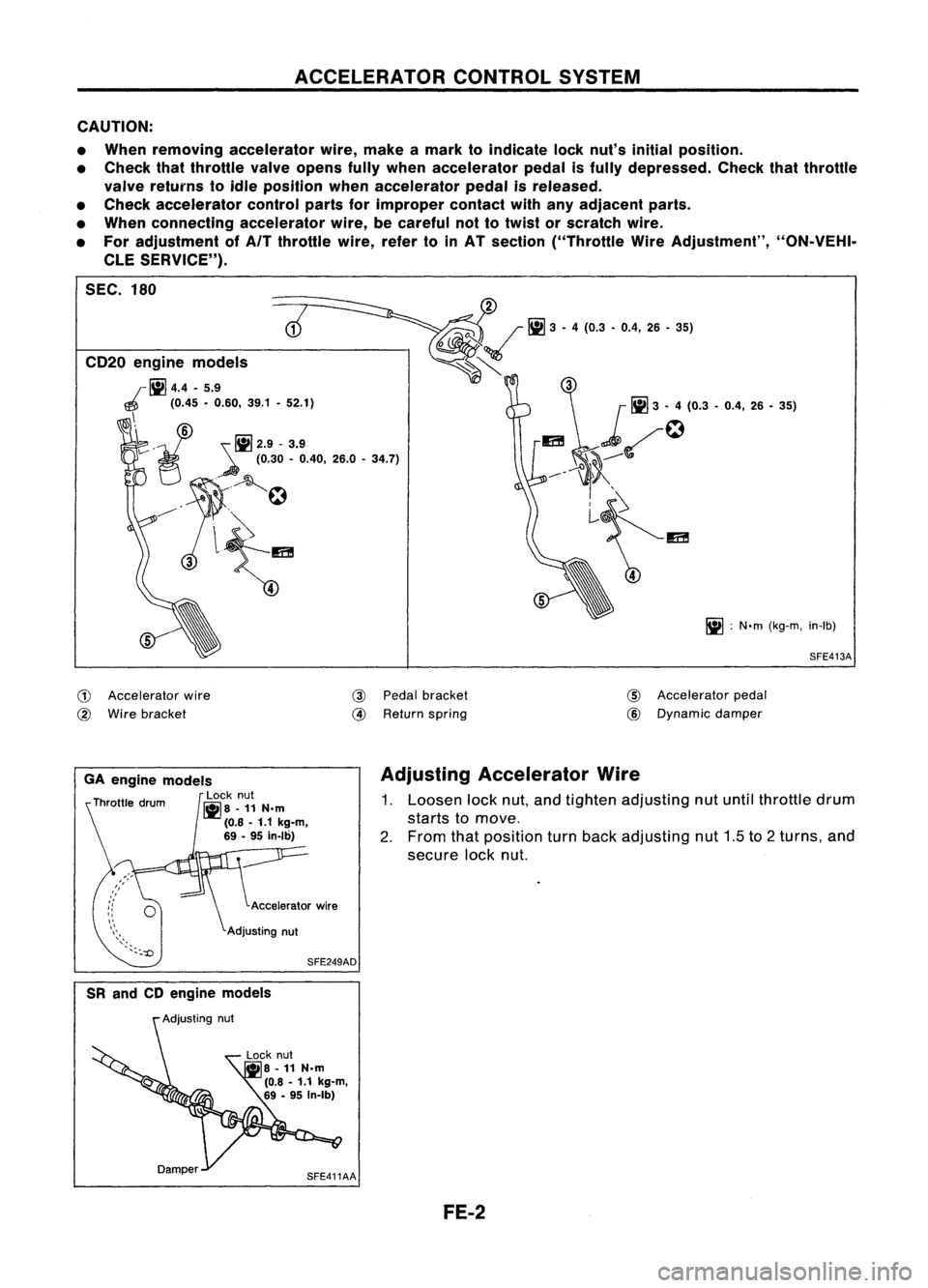
• When removing accelerator wire,make amark toindicate locknut's initial position.
• Check thatthrottle valveopens fullywhen accelerator pedalisfUlly depressed. Checkthatthrottle
valve returns toidle position whenaccelerator pedalisreleased.
• Check accelerator controlpartsforimproper contactwithanyadjacent parts.
• When connecting accelerator wire,becareful nottotwist orscratch wire.
• For adjustment ofAfT throttle wire,refertoinAT section ("Throttle WireAdjustment", "ON-VEHI-
CLE SERVICE").
SEC. 180
SFE413A
iii
:
N'm (kg-m, in-Ib)
5
~~
Iii]
3.4 (0.3 .0.4, 26.36)
~~~
5
CD20
engine models
r
1iI4.4 •5.9
~ (0.45-0.60, 39.1•52.1)
\i
v'
!il2.9-3.9
~ (0.30-0.40, 26.0-34.7)
7C
A~
~'
.
.
~
3l~
,
G)
Accelerator wire
@
Wire bracket
@
Pedal bracket
@
Return spring
CID
Accelerator pedal
@
Dynamic
damper
SFE249AD
GA
engine models
Locknut
~8 -11N.m
(0.8 -1.1 kg-m,
69 -95 in-Ib)
Adjusting
Accelerator Wire
1. Loosen locknut,andtighten adjusting nutuntil throttle drum
starts tomove.
2. From thatposition turnback adjusting nut1.5to2turns, and
secure locknut.
SR and CDengine models
Lock nut
• 8-11 N.m
(0.8 -1.1 kg-m,
69 -95 In-Ib)
SFE411AA FE-2
Page 715 of 1701
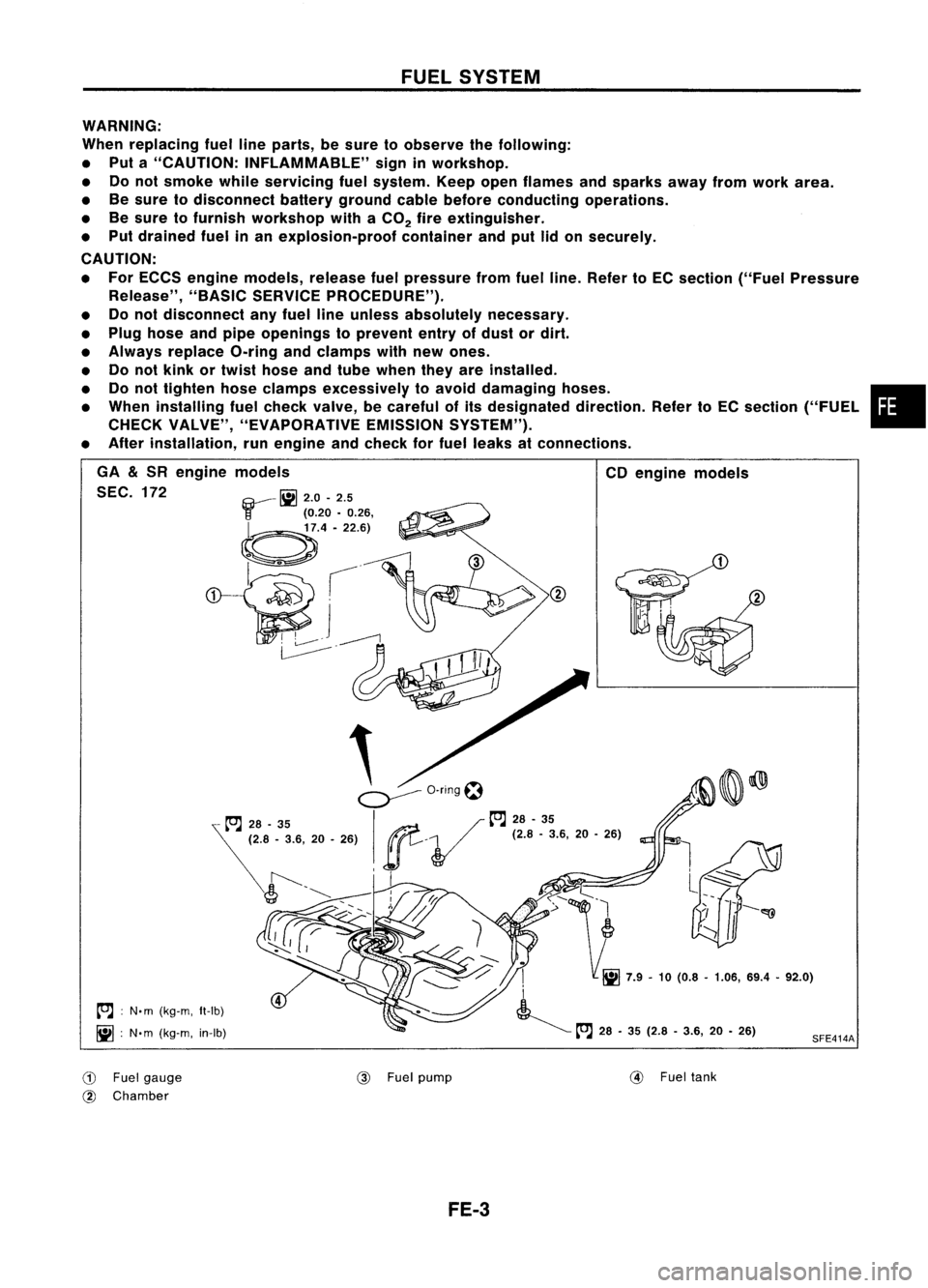
FUELSYSTEM
WARNING:
When replacing fuellineparts, besure toobserve thefollowing:
• Put a"CAUTION: INFLAMMABLE" signinworkshop.
• Donot smoke whileservicing fuelsystem. Keepopenflames andsparks awayfromwork area.
• Besure todisconnect batterygroundcablebefore conducting operations.
• Besure tofurnish workshop withaCO
2
fireextinguisher.
• Put drained fuelinan explosion-proof containerandputlidon securely.
CAUTION:
• For ECCS engine models, releasefuelpressure fromfuelline. Refer toEC section ("FuelPressure
Release", "BASICSERVICE PROCEDURE").
• Donot disconnect anyfuel lineunless absolutely necessary.
• Plug hose andpipe openings toprevent entryofdust ordirt.
• Always replace O-ringandclamps withnewones.
• Donot kink ortwist hose andtube when theyareinstalled.
• Donot tighten hoseclamps excessively toavoid damaging hoses. •
• When installing fuelcheck valve, becareful ofits designated direction.RefertoEC section ("FUEL
CHECK VALVE", "EVAPORATIVE EMISSIONSYSTEM").
• After installation, runengine andcheck forfuel leaks atconnections.
SFE414A
CD
engine models
.
I
i
~ tt'.J
28•35 (2.8 -3.6, 20•26)
,
.
~o-nngt:1
...,/ tt'.J
28-35
ge.
V
(2.'.3.6, 20•26)
, I
GA
&
SR engine models
SEC. 172 ~
2.0-2.5
r
(0.20•0.26,
~.4'22.6)
~ .---£l
~I
~j~
~.
tt'.J :
N. m (kg-m, It-Ib)
iii :
N'm (kg-m, in-Ib)
CD
Fuelgauge
@ Chamber @
Fuelpump
@
Fueltank
FE-3
Page 717 of 1701
SFE180A
SR engine models
SEC. 200-208
toJ
13-16 (1.3 -1.6, 9-12)
EXHAUST
SYSTEM
CAUTION:
• Always replace exhaust gasketswithnewones when reas-
sembling. If gasket isleft onflange surface, scrapeoffcompletely as
shown atleft.
• With engine running, checkalltube connections forexhaust
gas leaks, andentire system forunusual noises.
• After installation, checktoensure thatmounting brackets
and mounting insulators arefree from undue stress.
If
any
of the above partsarenotinstalled properly, excessive
noise orvibration maybetransmitted tothe vehicle body.
GaSket~
toJ:
N'm (kg-m, ft-Ib)
~ :N'm (kg-m, in-Ib)
SFE412A
FE-5
•