Page 1400 of 1701
SAEJ1930 TERMINOLOGY LIST
SAE J1930 Terminology List(Cont'd)
***:
Not applicable
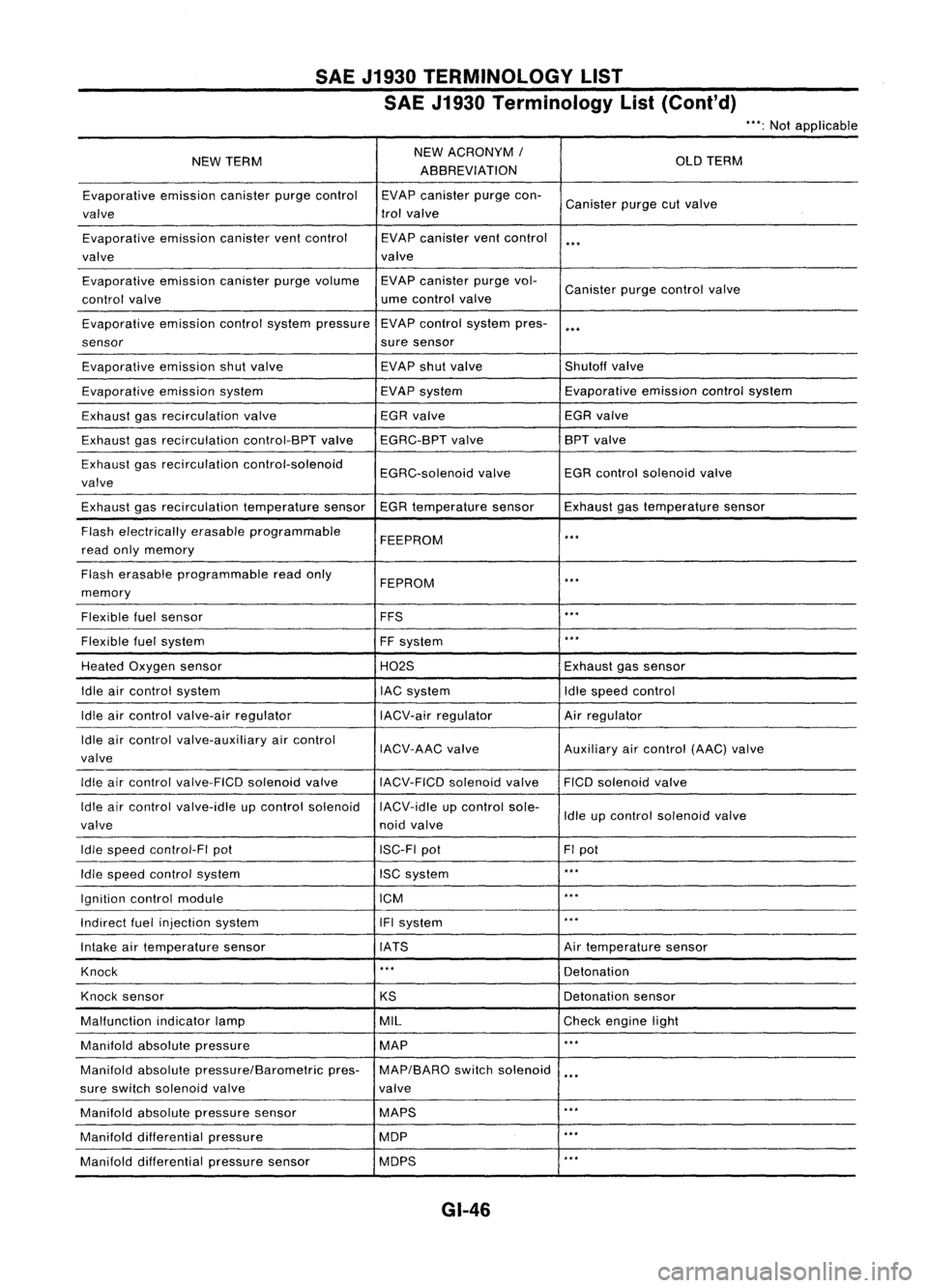
NEW TERM NEW
ACRONYM /
OLDTERM
ABBREVIATION
Evaporative emissioncanisterpurgecontrol EVAPcanister purgecon-
Canister purgecutvalve
valve trol
valve
Evaporative emissioncanisterventcontrol EVAPcanister ventcontrol
***
valve valve
Evaporative emissioncanisterpurgevolume EVAPcanister purgevol-
Canister purgecontrol valve
control valve ume
control valve
Evaporative emissioncontrolsystem pressure EVAP
control system pres-
***
sensor suresensor
Evaporative emissionshutvalve EVAP
shutvalve Shutoffvalve
Evaporative emissionsystem EVAPsystem Evaporative
emissioncontrolsystem
Exhaust gasrecirculation valve EGR
valve EGRvalve
Exhaust gasrecirculation control-BPTvalveEGRC-BPT valve BPT
valve
Exhaust gasrecirculation control-solenoid
EGRC-solenoidvalveEGR
control solenoid valve
valve
Exhaust gasrecirculation temperaturesensorEGRtemperature sensorExhaustgastemperature sensor
Flash electrically erasableprogrammable
FEEPROM
***
read onlymemory
Flash erasable programmable readonly
FEPROM
**.
memory
Flexible fuelsensor FFS
***
Flexible fuelsystem
FFsystem
***
Heated Oxygen sensor H02SExhaustgassensor
Idle aircontrol system lACsystem Idlespeed control
Idle aircontrol valve-air regulator IACV-airregulator Airregulator
Idle aircontrol valve-auxiliary aircontrol
IACV-AACvalve Auxiliaryaircontrol (AAC)valve
valve
Idle aircontrol valve-FICO solenoidvalve
IACV-FICDsolenoidvalve FICOsolenoid valve
Idle aircontrol valve-idle upcontrol solenoid IACV-idleupcontrol sole-
Idleupcontrol solenoid valve
valve noidvalve
Idle speed control-FI pot ISC-FIpot FIpot
Idle speed control system ISCsystem
***
Ignition controlmodule ICM
***
Indirect fuelinjection system IFIsystem
***
Intake airtemperature sensor IATS Airtemperature sensor
Knock
***
Detonation
Knock sensor
KSDetonation
sensor
Malfunction indicatorlamp MIL
Checkengine light
Manifold absolutepressure MAP
***
Manifold absolutepressure/Barometric pres-MAP/BARO switchsolenoid
***
sure switch solenoid valve valve
Manifold absolutepressure sensor MAPS
**.
Manifold differential pressure MOP
***
Manifold differential pressuresensor MOPS
***
GI-46
Page 1482 of 1701
SERVICEPROCEDURES
Thermal Protector
INSPECTION
• When servicing, donot allow foreign mattertoget into com-
pressor.
• Check continuity betweentwoterminals.
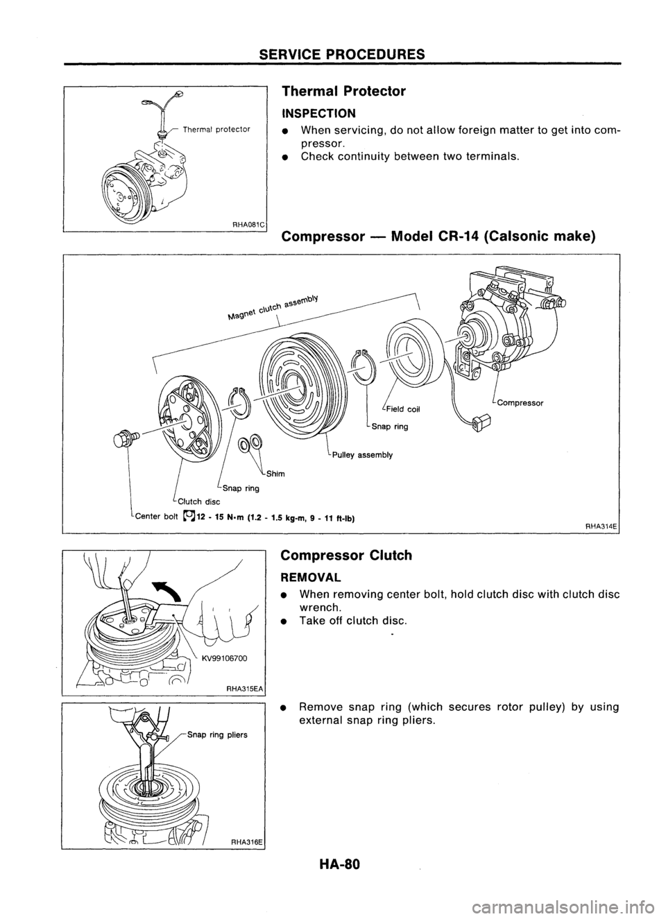
Compressor -Model CR-14(Calsonic make)
Pulley assembly
Snap ring
Clutch disc
Center bolt~12 -
15 N.m
(1.2-1.5 kg-m, 9-
11 ft-Ib)
RHA314E
Compressor Clutch
REMOVAL
• When removing centerbolt,holdclutch discwithclutch disc
wrench.
• Take offclutch disc.
• Remove snapring(which secures rotorpulley) byusing
external snapringpliers.
HA-80
Page 1483 of 1701
RHA317ESERVICE
PROCEDURES
Compressor Clutch(Cont'd)
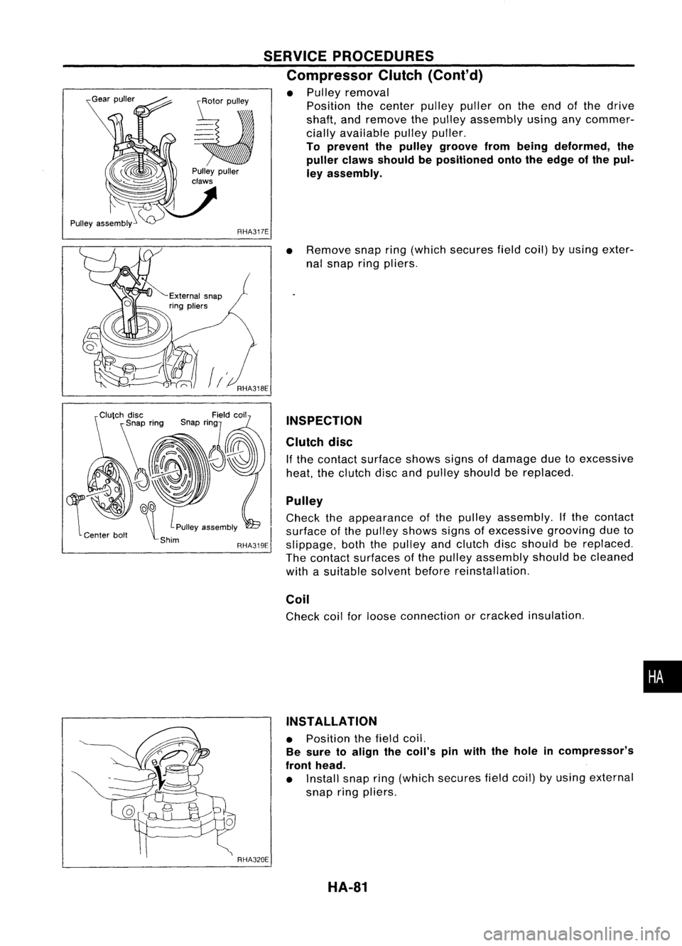
• Pulley removal
Position thecenter pulleypulleronthe end ofthe drive
shaft, andremove thepulley assembly usinganycommer-
cially available pulleypuller.
To prevent thepulley groove frombeing deformed, the
puller clawsshould bepositioned ontotheedge ofthe pul-
ley assembly.
~~
\t
PUlleyassembly
-Shim RHA319E
RHA320E
•
Remove snapring(which secures fieldcoil)byusing exter-
nal snap ringpliers.
INSPECTION
Clutch disc
If the contact surface showssignsofdamage duetoexcessive
heat, theclutch discandpulley should bereplaced.
Pulley
Check theappearance ofthe pulley assembly. Ifthe contact
surface ofthe pulley shows signsofexcessive groovingdueto
slippage, boththepulley andclutch discshould bereplaced.
The contact surfaces ofthe pulley assembly shouldbecleaned
with asuitable solventbeforereinstallation.
Coil
Check coilforloose connection orcracked insulation .
INSTALLATION
• Position thefield coil.
Be sure toalign thecoil's pinwith thehole incompressor's
front head.
• Install snapring(which secures fieldcoil)byusing external
snap ringpliers.
HA-81
•
Page 1484 of 1701
KV99106800
~ RHA321EA
~
s~
~ Clutchdisc
SERVICE
PROCEDURES
Compressor Clutch(Cont'd)
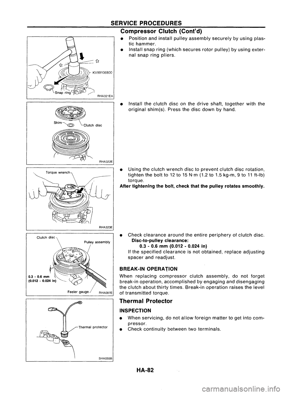
• Position andinstall pulleyassembly securelybyusing plas-
tic hammer.
• Install snapring(which secures rotorpulley) byusing exter-
nal snap ringpliers.
• Install theclutch disconthe drive shaft, together withthe
original shim(s). Pressthedisc down byhand.
RHA323E
Pulley assembly
SHA055B
•
Using theclutch wrench disctoprevent clutchdiscrotation,
tighten thebolt to12 to15 N'm (1.2to1.5 kg-m, 9to 11ft-Ib)
torque.
After tightening thebolt, check thatthepulley rotates smoothly.
• Check clearance aroundtheentire periphery ofclutch disc.
Disc-to-pulley clearance:
0.3 -0.6 mm (0.012 -0.024 in)
If the specified clearance isnot obtained, replaceadjusting
spacer andreadjust.
BREAK-IN OPERATION
When replacing compressor clutchassembly, donot forget
break-in operation, accomplished byengaging anddisengaging
the clutch aboutthirtytimes. Break-in operation raisesthelevel
of transmitted torque.
Thermal Protector
INSPECTION
• When servicing, donot allow foreign mattertoget into com-
pressor.
• Check continuity betweentwoterminals.
HA-82
Page 1485 of 1701
Ventilationairfilter
Evaporator SERVICE
PROCEDURES
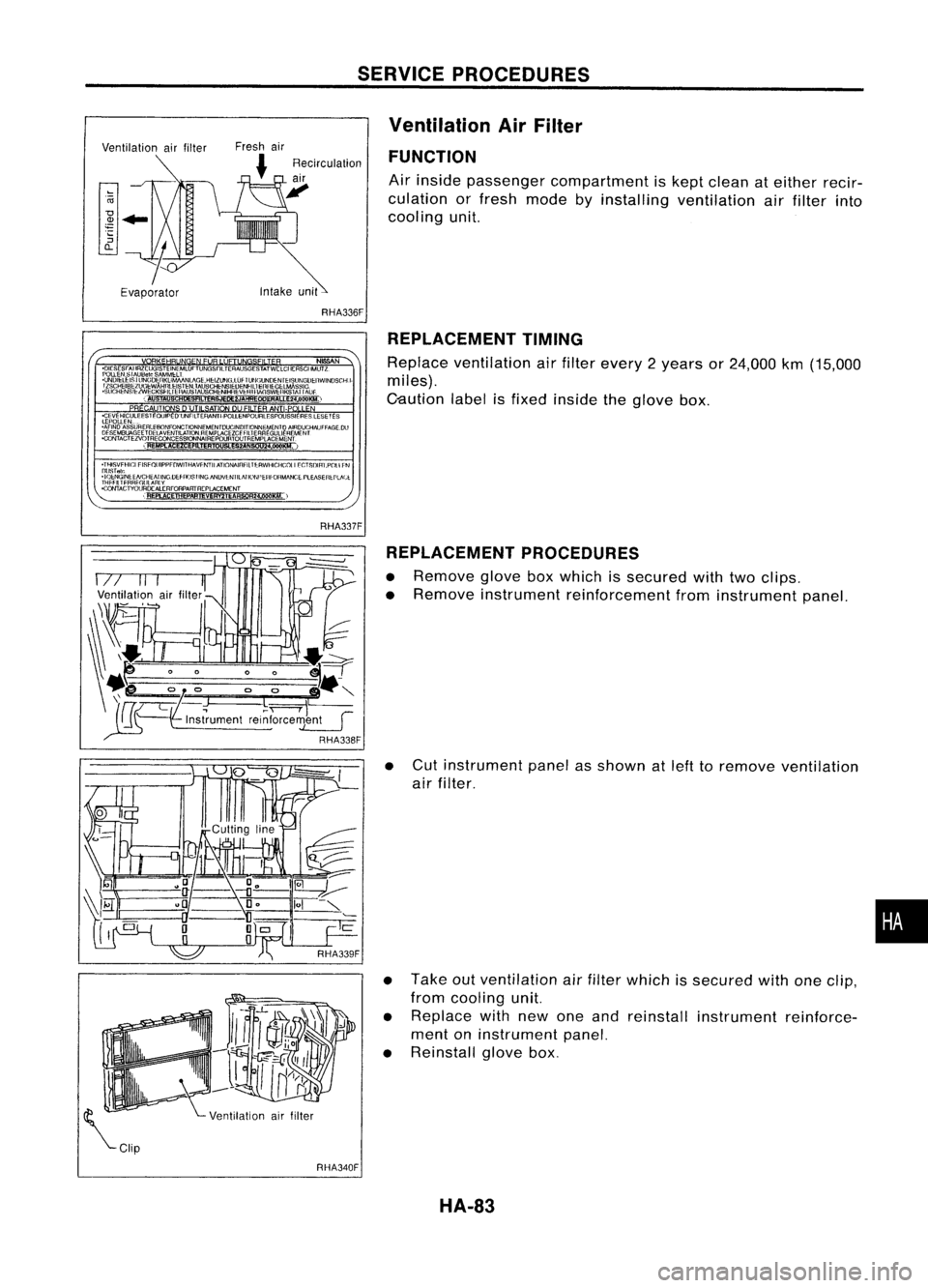
Ventilation AirFilter
FUNCTION
Air inside passenger compartment iskept clean ateither recir-
culation orfresh mode byinstalling ventilation airfilter into
cooling unit.
RHA336F REPLACEMENT TIMING
Replace ventilation airfilter every 2years or24,000 km(15,000
miles).
C-aution labelisfixed inside theglove box.
REPLACEMENT PROCEDURES
• Remove gloveboxwhich issecured withtwoclips.
• Remove instrument reinforcement frominstrument panel.
• Cut instrument panelasshown atleft toremove ventilation
air filter.
• Take outventilation airfilter which issecured withoneclip,
from cooling unit.
• Replace withnewoneand reinstall instrument reinforce-
ment oninstrument panel.
• Reinstall glovebox.
•
RHA340F HA-83
Page 1492 of 1701
GENERALMAINTENANCE
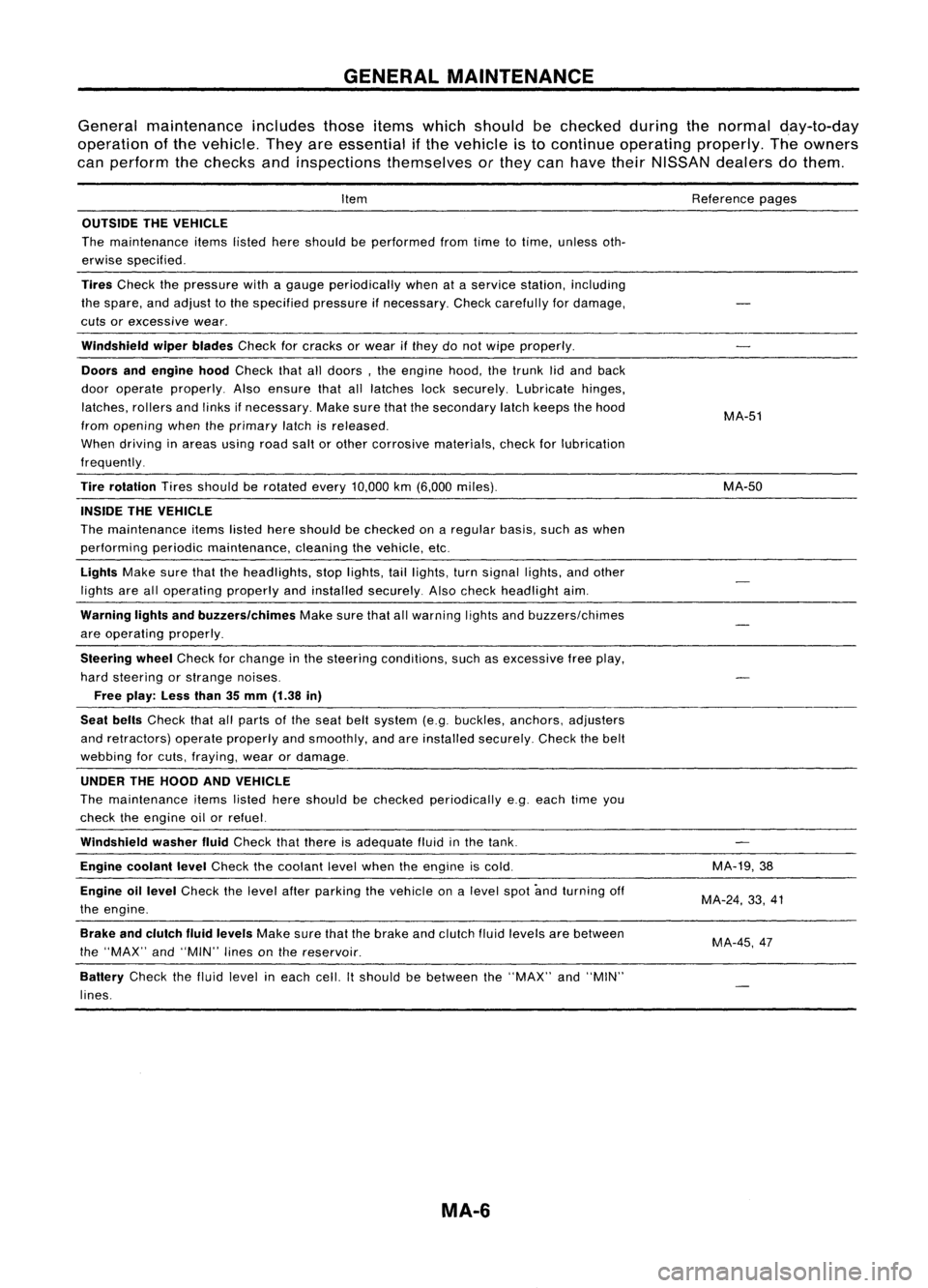
General maintenance includesthoseitemswhich should bechecked duringthenormal day-to-day
operation ofthe vehicle. Theyareessential ifthe vehicle isto continue operating properly.Theowners
can perform thechecks andinspections themselves orthey canhave theirNISSAN dealersdothem.
Item
OUTSIDE THEVEHICLE
The maintenance itemslistedhereshould beperformed fromtimetotime, unless oth-
erwise specified.
Tires
Check thepressure withagauge periodically whenataservice station, including
the spare, andadjust tothe specified pressureifnecessary. Checkcarefully fordamage,
cuts orexcessive wear.
Windshield wiperblades
Checkforcracks orwear ifthey donot wipe properly.
Doors andengine hood
Check thatalldoors, theengine hood,thetrunk lidand back
door operate properly. Alsoensure thatalllatches locksecurely. Lubricate hinges,
latches, rollersandlinks ifnecessary. Makesurethatthesecondary latchkeeps thehood
from opening whentheprimary latchisreleased.
When driving inareas usingroadsaltorother corrosive materials, checkforlubrication
frequently.
Tire rotation
Tiresshould berotated every
10,000
km
(6,000
miles).
INSIDE THEVEHICLE
The maintenance itemslistedhereshould bechecked onaregular basis,suchaswhen
performing periodicmaintenance, cleaningthevehicle, etc.
Lights
Makesurethattheheadlights, stoplights, taillights, turnsignal lights,andother
lights arealloperating properlyandinstalled securely. Alsocheck headlight aim.
Warning lightsandbuzzers/chimes
Makesurethatallwarning lightsandbuzzers/chimes
are operating properly.
Steering wheel
Check forchange inthe steering conditions, suchasexcessive freeplay,
hard steering orstrange noises.
Free play: Lessthan35mm (1.38 in)
Seat belts
Check thatallparts ofthe seat beltsystem (e.g.buckles, anchors, adjusters
and retractors) operateproperly andsmoothly, andareinstalled securely. Checkthebelt
webbing forcuts, fraying, wearordamage.
UNDER THEHOOD ANDVEHICLE
The maintenance itemslisted hereshould bechecked periodically e.g.each timeyou
check theengine oilorrefuel.
Windshield washerfluid
Check thatthere isadequate fluidinthe tank.
Engine coolant level
Check thecoolant levelwhen theengine iscold.
Engine oillevel
Check thelevel afterparking thevehicle onalevel spotandturning off
the engine.
Brake andclutch fluidlevels
Makesurethatthebrake andclutch fluidlevels arebetween
the "MAX" and"MIN" linesonthe reservoir.
Battery
Checkthefluid level ineach cell.Itshould bebetween the"MAX" and"MIN"
lines.
MA-6
Reference
pages
MA-51
MA-50
MA-19,38
MA-24, 33,41
MA-45,47
Page 1505 of 1701
ENGINEMAINTENANCE
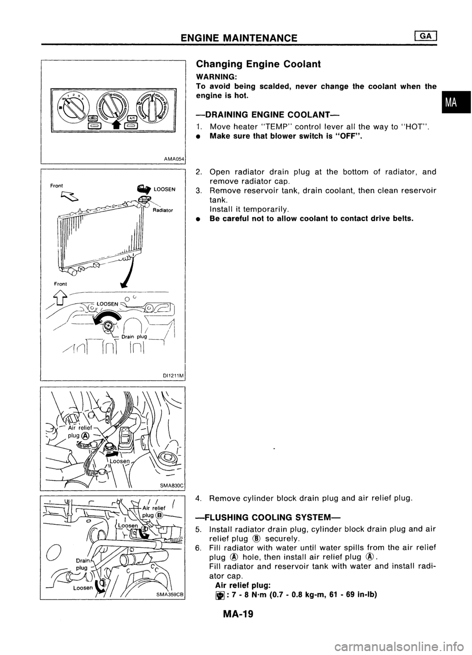
AMA054 Changing
EngineCoolant
WARNING:
To avoid being scalded, neverchange thecoolant whenthe
engine ishot.
-DRAINING ENGINECOOlANT-
1. Move heater "TEMP" controlleverallthe way to"HOT".
• Make surethatblower switchis"OFF".
•
Front
Fronl
'*'
LOOSEN
'--
Radialor
DI1211M
2.
Open radiator drainplugatthe bottom ofradiator, and
remove radiator cap.
3. Remove reservoir tank,drain coolant, thenclean reservoir
tank. Install ittemporarily.
• Becareful nottoallow coolant tocontact drivebelts.
4. Remove cylinder blockdrain plugandairrelief plug.
-FLUSHING COOLINGSYSTEM-
S. Install radiator drainplug,cylinder blockdrain plugandair
relief plug
CID
securely.
6. Fill radiator withwater untilwater spillsfromtheairrelief
plug @hole, theninstall airrelief plug@.
Fill radiator andreservoir tankwithwater andinstall radi-
ator cap.
Air relief plug:
~ :7 -
8 N'm (0.7-0.8 kg-m, 61-69 in-Ib)
MA-19
Page 1516 of 1701
Withheater
Withoutheater
M/T
6.1(5-3/8)
5.8(5-1/8)
AfT 6.6(5-7/8)
6.3(5-1/2)
Unit:
r
(Imp qt)
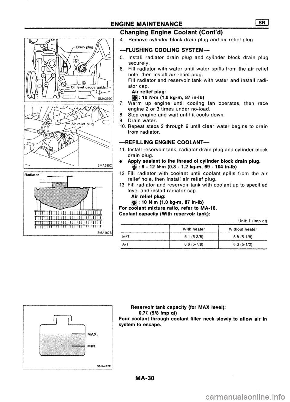
-FLUSHING
COOLINGSYSTEM-
5. Install radiator drainplugandcylinder blockdrainplug
securely.
6. Fill radiator withwater untilwater spillsfromtheairrelief
hole, theninstall airrelief plug.
Fill radiator andreservoir tankwithwater andinstall radi-
ator cap.
Air relief plug:
!II:
10N.m (1.0kg-m, 87in-lb)
7. Warm upengine untilcooling fanoperates, thenrace
engine 2or 3times under no-load.
8. Stop engine andwait until itcools down.
9. Drain water.
10. Repeat steps2through 9until clear water begins todrain
from radiator.
-REFILLING ENGINECOOLANT-
11. Install reservoir tank,radiator drainplugandcylinder block
drain plug.
• Apply sealant tothe thread ofcylinder blockdrainplug.
!II :
8 -12 N.m (0.8-1.2 kg-m, 69-104 in-lb)
12. Fill radiator withcoolant untilcoolant spillsfromtheair
relief hole,theninstall airrelief plug.
13. Fill radiator andreservoir tankwithcoolant uptospecified
level andinstall radiator cap.
Air relief plug:
~ :10 N'm (1.0kg-m, 87in-lb)
For coolant mixture ratio,refertoMA-16.
Coolant capacity (Withreservoir tank):
ENGINE
MAINTENANCE ~
Changing EngineCoolant (Cont'd)
4. Remove cylinderblockdrainplugandairrelief plug.
SMA380C
MAX.
MIN.
Reservoir
tankcapacity (forMAX level):
o.n
(5/8Impqt)
Pour coolant through coolantfillerneck slowly toallow airin
system toescape.
SMA4128 MA-30