Page 1653 of 1701
TROUBLEDIAGNOSES -Supplemental RestraintSystem(SRS)-
Dual AirBag System
Self-diagnosis (Cont'd)
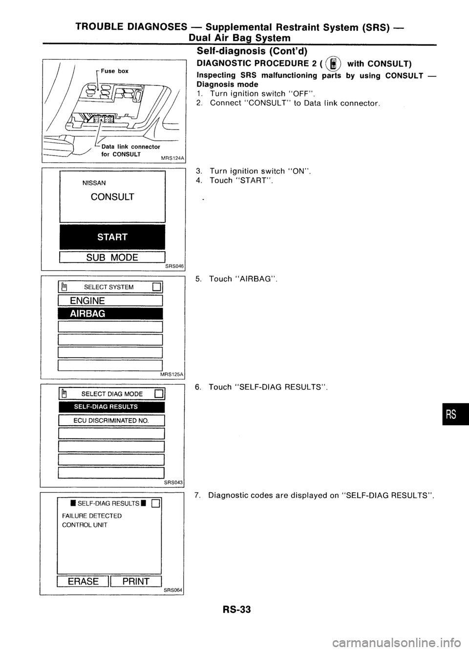
DIAGNOSTIC PROCEDURE2
(00
withCONSULT)
Inspecting SRSmalfunctioning partsbyusing CONSULT -
Diagnosis mode
1. Turn ignition switch"OFF".
2. Connect "CONSULT" toData linkconnector.
MRS124A
AIRBAG SELF-DIAG RESULTS
NISSAN
CONSULT
START
SUB MODE
I
SRS046
I ~
SELECT SYSTEM
01
I
ENGINE
1
1 '
1-----1
I
I
I 1
MRS125A
I ~
SELECT DIAGMODE
01
I
ECUDISCRIMINATED NO.
I
'======
1 -
1 -
1========
SRS043
• SELF-DIAG RESULTS.
0
FAILURE DETECTED
CONTROL UNIT
I
ERASE
II
PRINT
I
SRS064
3.
Turn ignition switch"ON".
4. Touch "START".
5. Touch "AIRBAG".
6. Touch "SELF-DIAG RESULTS".
7. Diagnostic codesaredisplayed on"SELF-DIAG RESULTS".
RS-33
•
Page 1677 of 1701
STEERINGWHEELANDSTEERING COLUMN
Removal andInstallation (Cont'd)
Two spoke type
Clamp
Crosshead screwdriver~
II
SST503C
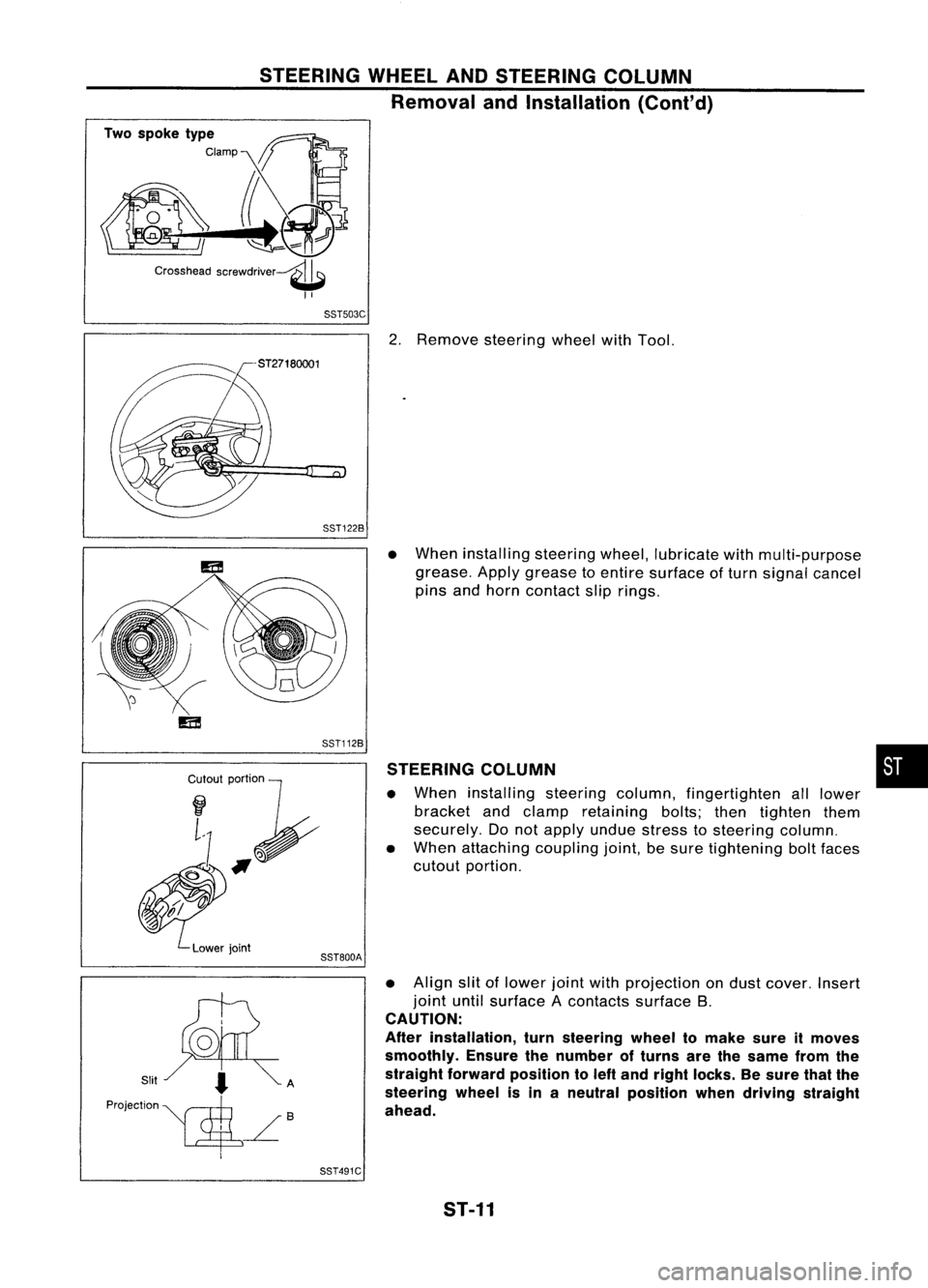
2.Remove steering wheelwithTool.
SST122B
Cr~I~I;~
~#f
~.'".
Lowerjoint
SST112B
SST800A
•
When installing steeringwheel,lubricate withmulti-purpose
grease. Applygrease toentire surface ofturn signal cancel
pins andhorn contact sliprings.
STEERING COLUMN
• When installing steeringcolumn,fingertighten alllower
bracket andclamp retaining bolts;thentighten them
securely. Donot apply undue stress tosteering column.
• When attaching couplingjoint,besure tightening boltfaces
cutout portion.
• Align slitoflower jointwithprojection ondust cover. Insert
joint untilsurface Acontacts surfaceB.
CAUTION:
After installation, turnsteering wheeltomake sureitmoves
smoothly. Ensurethenumber ofturns arethesame fromthe
straight forward position toleft and right locks. Besure thatthe
steering wheelisin aneutral position whendriving straight
ahead.
•
SST491C ST-11
Page 1682 of 1701
MANUALSTEERING GEARANDLINKAGE (ModelR24N)
Inspection (Cont'd)
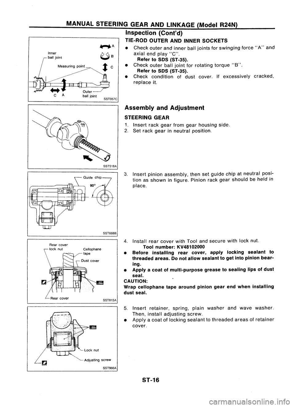
TIE-ROD OUTERANDINNER SOCKETS
...... A •
Check outerandinner balljoints for
swinging
force"A"and
axial endplay "C".
Refer toSOS CST-35).
Measuring point •
Check outerballjoint forrotating torque"B".
Refer toSOS CST-35).
• Check condition ofdust cover. Ifexcessively cracked,
replace it.
SST057C Assembly andAdjustment
STEERING GEAR
1. Insert rackgear from gearhousing side.
2. Set rack gear inneutral position.
SST518A
GO":,%?
'~
SST6688
3.
Insert pinion assembly, thensetguide chipatneutral posi-
tion asshown infigure. Pinionrackgear should be
held
in
place.
SST815A
4.
Install rearcover withTool andsecure withlocknut.
Tool number: KV48102000
• Before installing rearcover, applylocking sealant to
threaded areas.Donot allow sealant toget into pinion bear-
ing.
• Apply acoat ofmulti-purpose greasetosealing lipsofdust
seal.
CAUTION:
Wrap cellophane tapearound piniongearendwhen installing
dust seal.
5. Insert retainer, spring,plainwasher andwave washer.
Then, install adjusting screw.
• Apply acoat oflocking sealant tothreaded areasofretainer
cover.
Adjusting screw
SST966A
5T-16
Page 1686 of 1701
POWERSTEERING GEARANDLINKAGE (ModelPR24AC)
Removal andInstallation (Cont'd)
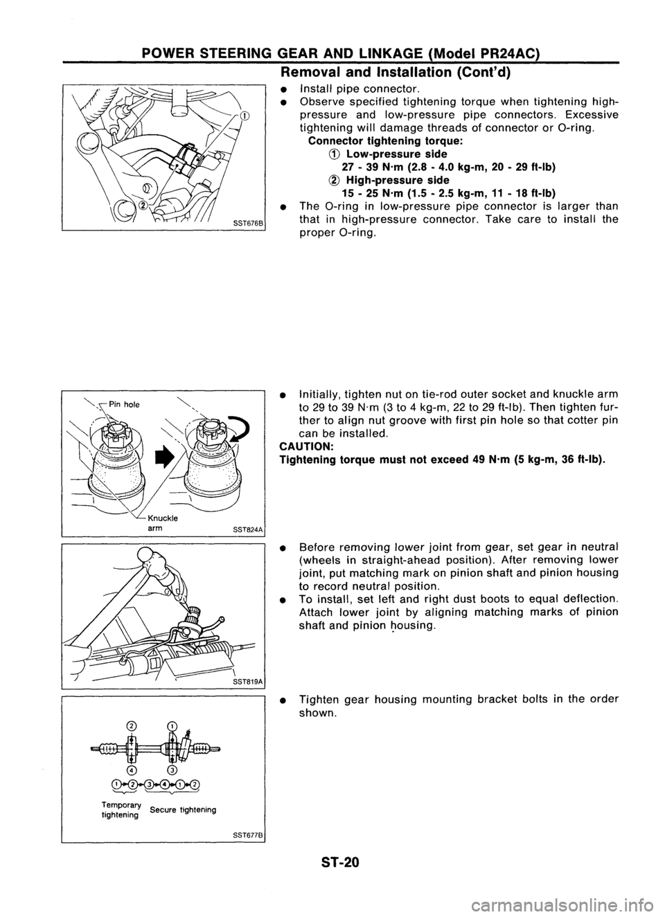
• Install pipeconnector.
• Observe specified tightening torquewhentightening high-
pressure andlow-pressure pipeconnectors. Excessive
tightening willdamage threadsofconnector orO-ring.
Connector tighteningtorque:
CD
Low-pressure side
27 -39 N'm (2.8-4.0 kg-m, 20-29 ft-Ib)
~ High-pressure side
15 -25 N'm (1.5-2.5 kg-m, 11-18 ft-Ib)
• The O-ring inlow-pressure pipeconnector islarger than
that inhigh-pressure connector.Takecaretoinstall the
proper O-ring.
• Initially, tightennutontie-rod outersocket andknuckle arm
to 29 to39 N'm (3to 4kg-m, 22to29 ft-Ib). Thentighten fur-
ther toalign nutgroove withfirstpinhole sothat cotter pin
can beinstalled.
CAUTION:
Tightening torquemustnotexceed 49N'm (5kg-m, 36ft-Ib).
• Before removing lowerjointfrom gear, setgear inneutral
(wheels instraight-ahead position).Afterremoving lower
joint, putmatching markonpinion shaftandpinion housing
to record neutral position.
• Toinstall, setleftand right dustboots toequal deflection.
Attach lowerjointbyaligning matching marksofpinion
shaft andpinion ~ousing.
• Tighten gearhousing mounting bracketboltsinthe order
shown.
o
@
~
'--v---' ~
Temporary ..
tightening SecuretIghtening
SST6778
ST-20
Page 1689 of 1701
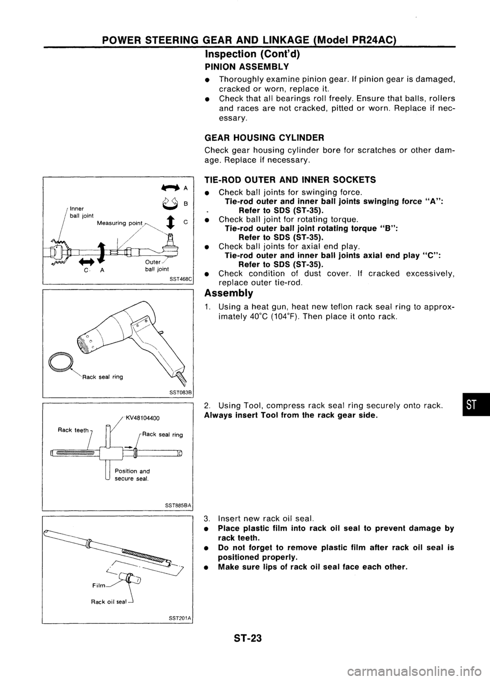
POWERSTEERING GEARANDLINKAGE (ModelPR24AC)
Inspection (Cont'd)
PINION ASSEMBLY
• Thoroughly examinepiniongear.Ifpinion gearisdamaged,
cracked orworn, replace it.
• Check thatallbearings rollfreely. Ensure thatballs, rollers
and races arenotcracked, pittedorworn. Replace ifnec-
essary.
GEAR HOUSING CYLINDER
Check gearhousing cylinder boreforscratches orother dam-
age. Replace ifnecessary.
SST083B
•
2.
Using Tool,compress rackseal ringsecurely ontorack.
Always insertToolfrom therack gear side.
TIE-ROD
OUTERANDINNER SOCKETS
• Check balljoints forswinging force.
Tie-rod outerandinner ball
joints
swinging force
"A":
Refer toSOS (ST-35).
• Check balljoint forrotating torque.
Tie-rod outerballjoint rotating torque
"B":
Refer to50S (ST-35).
• Check balljoints foraxial endplay.
Tie-rod outerandinner balljoints axialendplay
"e":
Refer to50S (ST-35).
• Check condition ofdust cover. Ifcracked excessively,
replace outertie-rod.
Assembly
1. Using aheat gun,heat newteflon rackseal ringtoapprox-
imately 40°C(104°F). Thenplace
it
onto rack.
Us
Rack sealring
Inner
ball joint
+
Measuring pOin;~~
+
C
/'
~R"k ,.. I
""9
Position and
secure seal.
SST885BA
c--.~
~
Film
Rack oilseal 3.
Insert newrack oilseal.
• Place plastic filmintorack oilseal toprevent damage by
rack teeth.
• Donot forget toremove plasticfilmafter rackoilseal is
positioned properly.
• Make surelipsofrack oilseal face each other.
SST201A ST-23