1995 NISSAN ALMERA N15 ECU
[x] Cancel search: ECUPage 1332 of 1701
Enginefront1
t;J
SEM230F
~~~:::~"
IJ
~ 2ndring
SEM909 CYLINDER
BLOCK
[ill
Assembly (Cont'd)
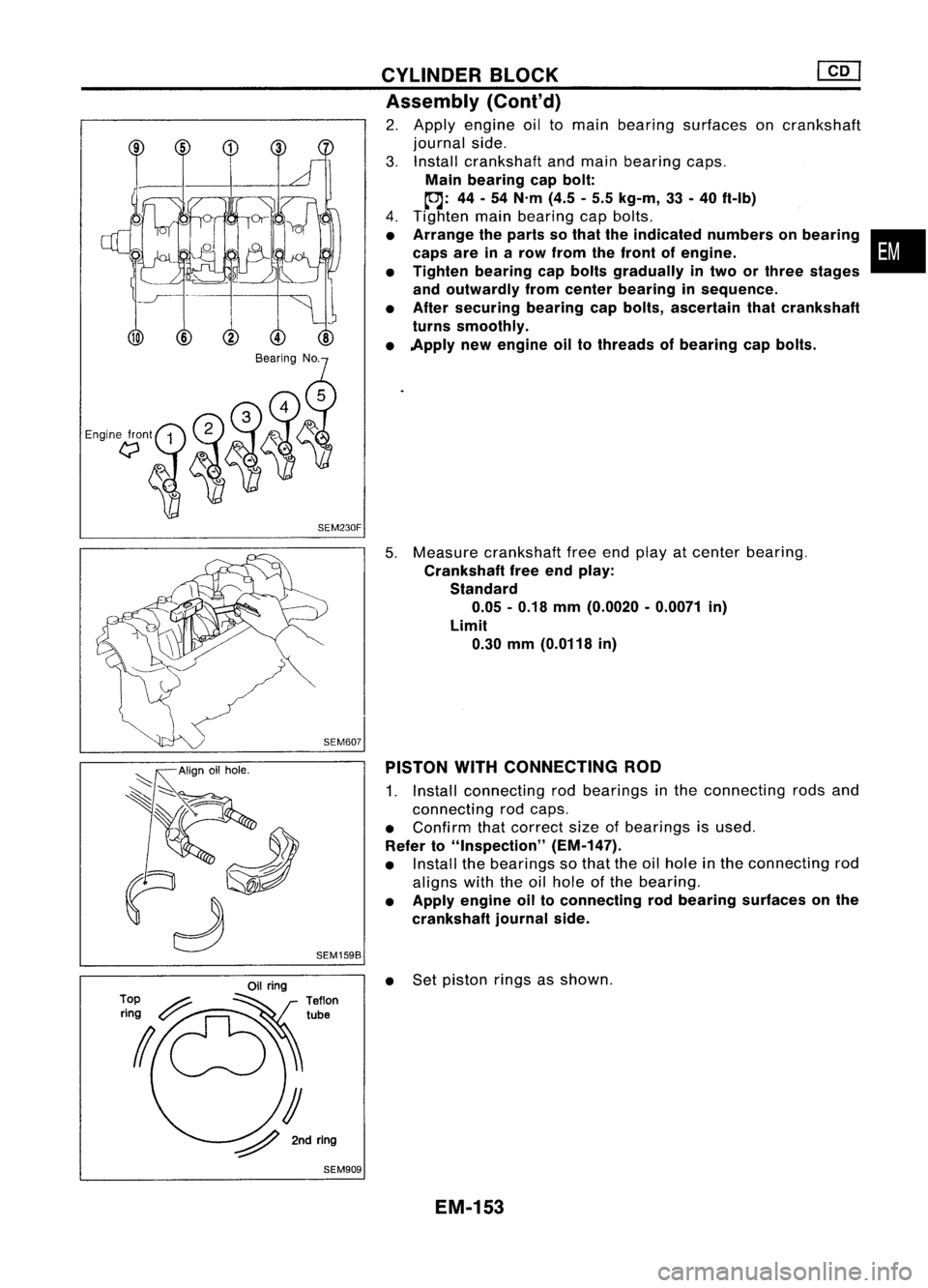
2. Apply engine oiltomain bearing surfaces oncrankshaft
journal side.
3. Install crankshaft andmain bearing caps.
Main bearing capbolt:
~: 44-54 N'm (4.5-5.5 kg-m, 33-40 ft-Ib)
4. Tighten mainbearing capbolts.
• Arrange theparts sothat theindicated numbersonbearing •
caps areinarow from thefront ofengine.
• Tighten bearing capbolts gradually intwo orthree stages
and outwardly fromcenter bearing insequence.
• After securing bearingcapbolts, ascertain thatcrankshaft
turns smoothly.
• Apply newengine oiltothreads ofbearing capbolts.
5. Measure crankshaft freeendplay atcenter bearing.
Crankshaft freeendplay:
Standard 0.05 -0.18 mm(0.0020 -0.0071 in)
Limit 0.30 mm(0.0118 in)
PISTON WITHCONNECTING ROD
1. Install connecting rodbearings inthe connecting rodsand
connecting rodcaps.
• Confirm thatcorrect sizeofbearings isused.
Refer to"Inspection" (EM-147).
• Install thebearings sothat theoilhole inthe connecting rod
aligns withtheoilhole ofthe bearing.
• Apply engine oiltoconnecting rodbearing surfaces onthe
crankshaft journalside.
• Set piston ringsasshown.
EM-153
Page 1357 of 1701
SGI916PRECAUTIONS
• Donot use electrical testequipment onany circuit related •
to the SRS unless instructed tointhis Service Manual.
Precautions forNATS V2.0(ForGasoline Engine
Model)
NATS (Nissan Anti-Theft System)
NATS V2.0willimmobilize theengine ifsomeone triestostart
it without theregistered keyofNATS V2.0.
Both ofthe originally suppliedignitionkeyIDshave been NATS
registered.
The NATS security indicator islocated onthe instrument panel.
The indicator blinkswhentheignition switchisin "OFF" or
"ACC" position. Therefore, NATSwarns outsiders thatthevehi-
cle isequipped withtheanti-theft system.
• When NATSdetects trouble, themalfunction indicatorlamp
(MIL) blinks.
This blinking indicates thattheanti-theft isnot functioning,
so prompt service isrequired.
• When servicing NATS(trouble diagnoses, systeminitialisa-
tion andadditional registration ofother NATS ignition key
IDs), CONSULT hardwareandCONSULT NATSsoftware is
necessary.
Regarding theprocedures ofNATS initialisation andNATS
ignition key
10
registration, refertoCONSULT operation
manual, NATSV2.0.
Therefore, CONSULTNATSsoftware (program cardandoper-
ation manual) mustbekept strictly confidential tomaintain the
integrity ofthe anti-theft function.
• When servicing NATSV2.0(trouble diagnoses, systemini-
tial isation andadditional registration ofother NATS ignition
key IDs),
it
may benecessary tore-register originalkey
identification. Therefore,besure toreceive allkeys from
vehicle owner.
A maximum offour keyIDscan beregistered intoNATS.
• When failing tostart theengine first-time usingthekey of
NATS V2.0,startasfollows.
(1) Turn ignition keyto"OFF".
(2) Wait approx. 5seconds.
(3) Turn ignition keyto"START" againwhilekeeping the
key apart fromanyothers onkey-chain.
SGI285 General
Precautions
• Donot operate theengine foranextended periodoftime
without properexhaust ventilation.
Keep thework areawellventilated andfree ofany flamma-
ble materials. Specialcareshould betaken whenhandling
any flammable orpoisonous materials,suchasgasoline,
refrigerant gas,etc.When working inapit orother enclosed
area, besure toproperly ventilate thearea before working
with hazardous materials.
Do not smoke whileworking onthe vehicle.
GI-3
Page 1365 of 1701
HOWTOREAD WIRING DIAGRAMS
Description
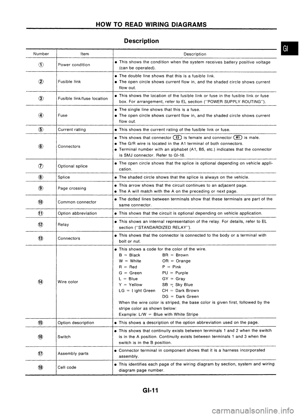
Number Item Description
CD
Power
condition •
This shows thecondition whenthesystem receives batterypositive voltage
(can beoperated) .
• The double lineshows thatthisisafusible link.
@
Fusiblelink
•The open circle shows current flowin,and theshaded circleshows current
flow out.
link/fuse location •
This shows thelocation ofthe fusible linkorfuse inthe fusible linkorfuse
box. Forarrangement, refertoEL section ("POWER SUPPLYROUTING") .
• The single lineshows thatthisisafuse.
@
Fuse
•The open circle shows current flowin,and theshaded circleshows current
flow out.
CID
Current
rating
•This shows thecurrent ratingofthe fusible linkorfuse .
• This shows thatconnector
@)
isfemale andconnector
@
ismale .
@
Connectors •
The G/R wire islocated inthe A1 terminal ofboth connectors.
• Terminal numberwithanalphabet (A1, B5, etc.) indicates thattheconnector
is SMJ connector. RefertoGI-16 .
rJ)
Optionalsplice •
The open circle shows thatthesplice isoptional depending onvehicle appli-
cation.
@
Splice •The shaded circleshows thatthesplice isalways onthe vehicle.
@
Page
crossing •
This arrow shows thatthecircuit continues toan adjacent page.
• The Awill match withtheAon the preceding ornext page .
@)
Commonconnector •
The dotted linesbetween terminals showthatthese terminals arepart ofthe
same connector.
@
Option
abbreviation •This shows thatthecircuit isoptional depending onvehicle application.
@
Relay •
This shows aninternal representation ofthe relay. Fordetails, refertoEL
section ("STANDARDIZED RELAY").
@
Connectors •
This shows thattheconnector isconnected tothe body oraterminal with
bolt ornut.
• This shows acode forthe color ofthe wire.
B
=
Black BR
=
Brown
W
=
White OR
=
Orange
R
=
Red P
=
Pink
G
=
Green PU
=
Purple
@
Wire
color L
=
Blue GY
=
Gray
Y
=
Yellow SB
=:
Sky Blue
LG
=
Light Green CH
=
Dark Brown
DG
=
Dark Green
When thewire color isstriped, thebase color isgiven first,followed bythe
stripe colorasshown below:
Example: LlW
=
Blue withWhite Stripe
@
Optiondescription •
This shows adescription ofthe option abbreviation usedonthe page.
• This shows thatcontinuity existsbetween terminals 1and 2when theswitch
@)
Switch is
inthe Aposition. Continuity existsbetween terminals 1and 3when the
switch isinthe Bposition .
@
Assembly
parts •
Connector terminalincomponent showsthatitis aharness incorporated
assembly .
@
Cell
code •
This identifies eachpage ofthe wiring diagram bysection, systemandwiring
diagram pagenumber.
GI-11
•
Page 1372 of 1701
HOWTOPERFORM EFFICIENT DIAGNOSIS FORANELECTRICAL INCIDENT
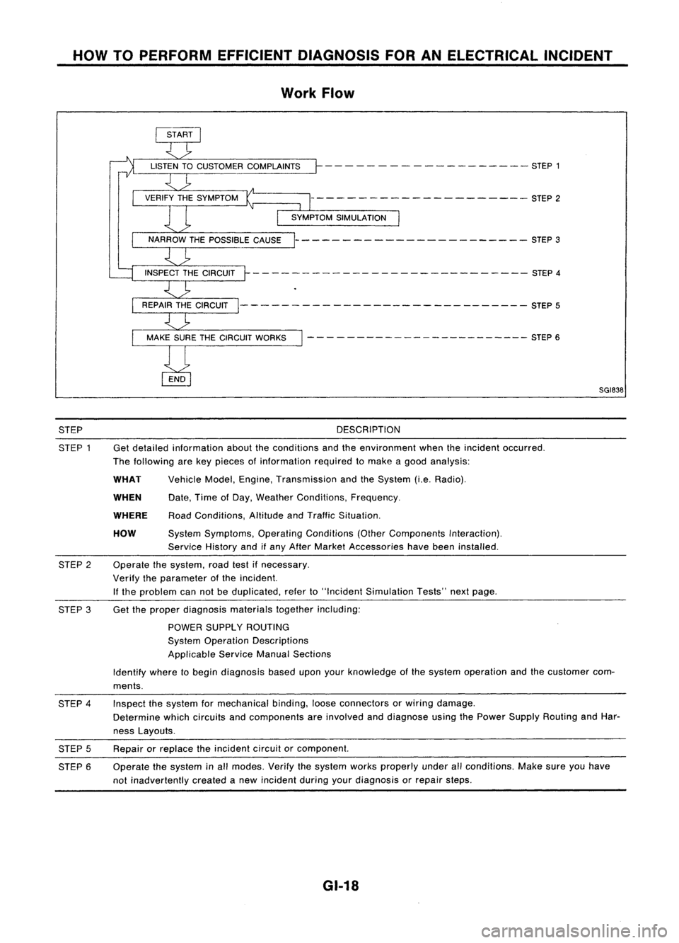
Work Flow
- - - -- - -- ------ -- - -- STEP 1
--------------------- STEP2
----------------------- STEP3
- - -- ---- - --- - -- --- --- - - --- -- STEP 4
--------- -------------------- STEP5
- - - - ---- -- -- -- -- -- --- --- STEP 6
SGI838
STEP
STEP 1 DESCRIPTION
Get detailed information abouttheconditions andtheenvironment whentheincident occurred.
The following arekey pieces ofinformation requiredtomake agood analysis:
HOW
WHEN
WHAT
WHERE
Vehicle
Model,Engine, Transmission andtheSystem (i.e.Radio).
Date, TimeofDay, Weather Conditions, Frequency.
Road Conditions, AltitudeandTraffic Situation.
System Symptoms, OperatingConditions (OtherComponents Interaction).
Service Historyandifany After Market Accessories havebeen installed.
Operate thesystem, roadtestifnecessary.
Verify theparameter ofthe incident.
If the problem cannotbeduplicated, referto"Incident Simulation Tests"nextpage.
STEP
2
STEP 3Get
theproper diagnosis materialstogetherincluding:
POWER SUPPLY ROUTING
System Operation Descriptions
Applicable ServiceManualSections
Identify wheretobegin diagnosis baseduponyourknowledge ofthe system operation andthecustomer com-
ments.
STEP 4
STEP 5
STEP 6 Inspect
thesystem formechanical binding,looseconnectors orwiring damage.
Determine whichcircuits andcomponents areinvolved anddiagnose usingthePower Supply Routing andHar-
ness Layouts.
Repair orreplace theincident circuitorcomponent.
Operate thesystem inall modes. Verifythesystem worksproperly underallconditions. Makesureyouhave
not inadvertently createdanew incident duringyourdiagnosis orrepair steps.
GI-18
Page 1373 of 1701
HOWTOPERFORM EFFICIENT DIAGNOSIS FORANELECTRICAL INCIDENT
Incident Simulation Tests
INTRODUCTION
Sometimes thesymptom isnot present whenthevehicle isbrought infor service.
If
possible, re-create
the conditions presentatthe time ofthe incident. Doingsomay help avoid aNo Trouble FoundDiag-
nosis. Thefollowing sectionillustrates waystosimulate theconditionslenvironment underwhich the
owner experiences anelectrical incident.
The section isbroken intothesixfollowing topics:
• Vehicle vibration
• Heat sensitive
• Freezing
• Water intrusion
• Electrical load
• Cold orhot start up
Get athorough description ofthe incident fromthecustomer. Itis important forsimulating thecondi-
tions ofthe problem.
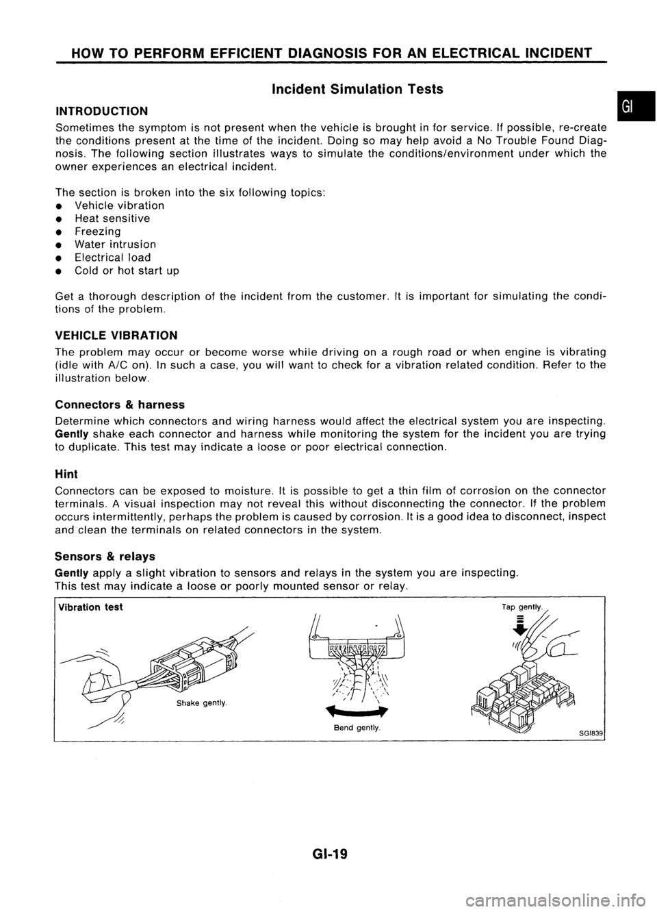
VEHICLE VIBRATION
The problem mayoccur orbecome worsewhiledriving onarough roadorwhen engine isvibrating
(idle with
AIC
on). Insuch acase, youwillwant tocheck foravibration relatedcondition. Refertothe
illustration below.
Connectors
&
harness
Determine whichconnectors andwiring harness wouldaffecttheelectrical systemyouareinspecting.
Gently
shakeeachconnector andharness whilemonitoring thesystem forthe incident youaretrying
to duplicate. Thistestmay indicate aloose orpoor electrical connection.
Hint
Connectors canbeexposed tomoisture. Itis possible toget athin film ofcorrosion onthe connector
terminals. Avisual inspection maynotreveal thiswithout disconnecting theconnector. Ifthe problem
occurs intermittently, perhapstheproblem iscaused bycorrosion. Itis agood ideatodisconnect, inspect
and clean theterminals onrelated connectors inthe system.
Sensors
&
relays
Gently
applyaslight vibration tosensors andrelays inthe system youareinspecting.
This testmay indicate aloose orpoorly mounted sensororrelay.
•
Vibration test
Bendgently.
GI-19
Tap
gently.
8GI839
Page 1379 of 1701
HOWTOPERFORM EFFICIENT DIAGNOSIS FORANELECTRICAL INCIDENT
Circuit Inspection (Cont'd)
Voltage checkmethod
1. Remove theblown fuseanddisconnect allloads (i.e.SW1 open, relaydisconnected andsolenoid •
disconnected) poweredthroughthefuse.
2. Turn theignition keytothe ONorSTART position. Verifybattery voltage atthe B
+
side ofthe fuse
terminal (oneleadonthe B
+
terminal sideofthe fuse block andone lead onaknown goodground).
3. With SW1 open andtheDMM leads across bothfuseterminals, checkforvoltage.
voltage; shortisbetween fuseblock andSW1 (point A).
no voltage; shortisfurther downthecircuit thanSW1.
4. With SW1 closed, relayandsolenoid disconnected andtheDMM leadsacross bothfuseterminals,
check forvoltage.
voltage; shortisbetween SW1andtherelay (point B).
no voltage; shortisfurther downthecircuit thantherelay.
5. With SW1 closed, relaycontacts jumpedwithfused jumper wirecheck forvoltage.
voltage; shortisdown thecircuit ofthe relay orbetween therelay andthedisconnected sole-
noid (point C).
no voltage; retracestepsandcheck power tofuse block.
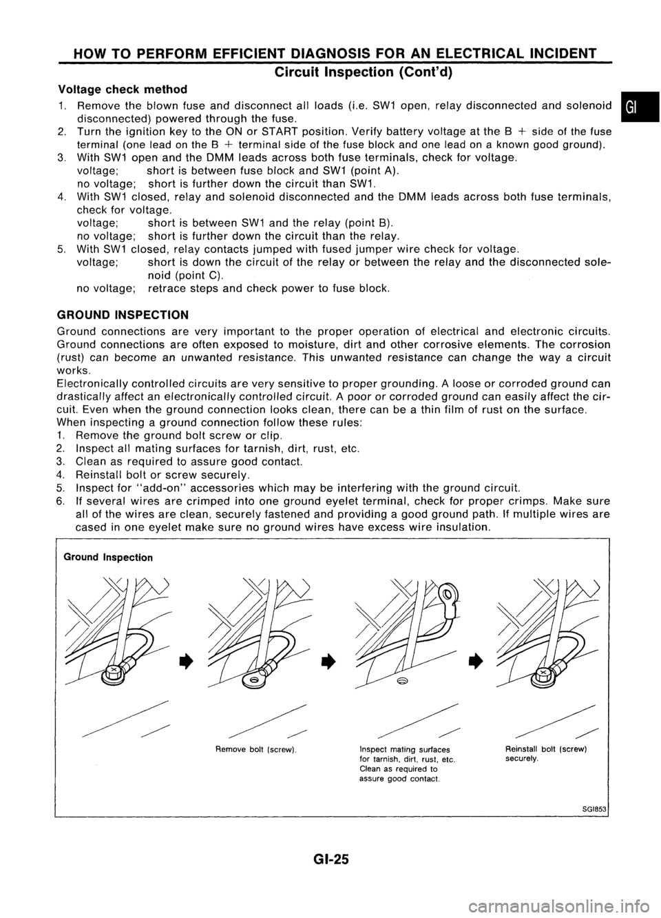
GROUND INSPECTION
Ground connections arevery important tothe proper operation ofelectrical andelectronic circuits.
Ground connections areoften exposed tomoisture, dirtand other corrosive elements. Thecorrosion
(rust) canbecome anunwanted resistance. Thisunwanted resistance canchange theway acircuit
works. Electronically controlledcircuitsarevery sensitive toproper grounding. Aloose orcorroded groundcan
drastically affectanelectronically controlledcircuit.Apoor orcorroded groundcaneasily affectthecir-
cuit. Even when theground connection looksclean, therecanbeathin film ofrust onthe surface.
When inspecting aground connection followtheserules:
1. Remove theground boltscrew orclip.
2. Inspect allmating surfaces fortarnish, dirt,rust, etc.
3. Clean asrequired toassure goodcontact.
4. Reinstall boltorscrew securely.
5. Inspect for"add-on" accessories whichmaybeinterfering withtheground circuit.
6. Ifseveral wiresarecrimped intoone ground eyeletterminal, checkforproper crimps. Makesure
all ofthe wires areclean, securely fastened andproviding agood ground path.Ifmultiple wiresare
cased inone eyelet makesurenoground wireshaveexcess wireinsulation.
Ground Inspection
•
Removeboll(screw).
•
GI-25
Inspect
matingsurfaces
for tarnish. dirt.rust. etc.
Clean asrequired to
assure goodcontact.
•
Reinstallbolt(screw)
securely.
SGI853
Page 1380 of 1701
HOWTOPERFORM EFFICIENT DIAGNOSIS FORANELECTRICAL INCIDENT
Circuit Inspection (Cont'd)
VOLTAGE DROPTESTS
Voltage droptests areoften usedtofind components orcircuits whichhaveexcessive resistance. A
voltage dropinacircuit iscaused byaresistance
whenthecircuit isin operation.
Check thewire inthe illustration. Whenmeasuring resistancewithohmmeter, contactbyasingle strand
of wire willgive reading of0ohms. Thiswould indicate agood circuit. Whenthecircuit operates, this
single strand ofwire isnot able tocarry thecurrent. Thesingle strand willhave ahigh resistance tothe
current. Thiswillbepicked upasaslight voltage drop.
Unwanted resistance canbecaused bymany situations asfollows:
Undersized wiring(single strandexample)
Corrosion onswitch contacts
Loose wireconnections orsplices.
If
repairs areneeded alwaysusewire thatisof the same orlarger gauge.
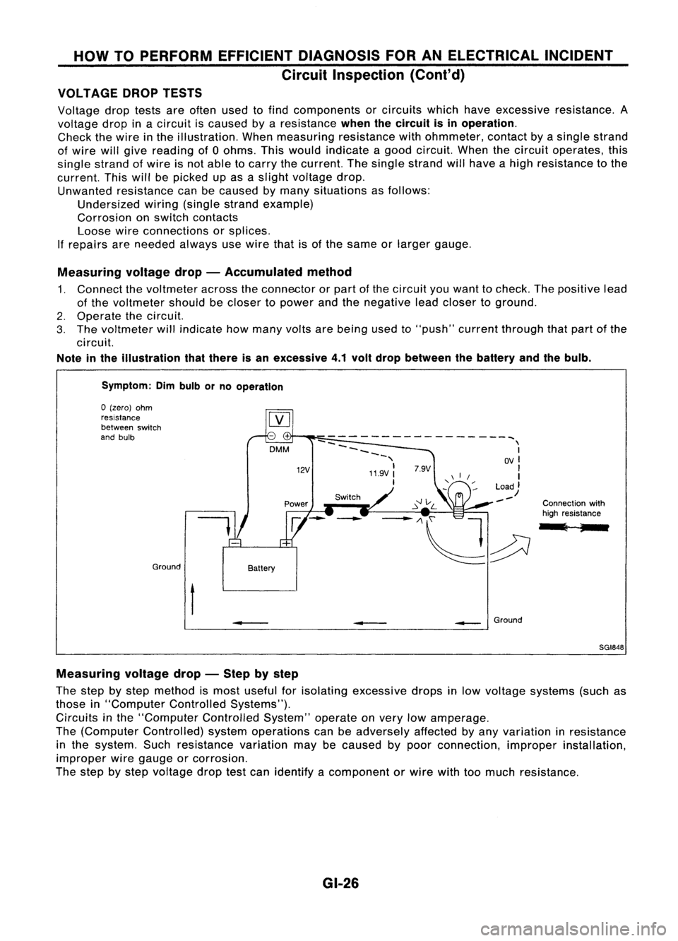
Measuring voltagedrop-Accumulated method
1. Connect thevoltmeter acrosstheconnector orpart ofthe circuit youwant tocheck. Thepositive lead
of the voltmeter shouldbecloser topower andthenegative leadcloser toground.
2. Operate thecircuit.
3. The voltmeter willindicate howmany voltsarebeing usedto"push" current through thatpart ofthe
circuit.
Note inthe illustration thatthere isan excessive 4.1volt drop between thebattery andthebulb.
Symptom: Dimbulb orno operation
Switch Connectionwith
high resistance
l ;
--
------------------~
--
\
~~~~ I
-, OVI
11.9V:
'I
I
Load)
--
12V
DMM
Battery
Ground
o
(zero) ohm
resistance
between switch
and bulb
t
•
__
Ground
SGI848
Measuring voltagedrop-Step bystep
The step bystep method ismost useful forisolating excessive dropsinlow voltage systems (suchas
those in"Computer ControlledSystems").
Circuits inthe "Computer ControlledSystem"operateonvery lowamperage.
The (Computer Controlled) systemoperations canbeadversely affectedbyany variation inresistance
in the system. Suchresistance variationmaybecaused bypoor connection, improperinstallation,
improper wiregauge orcorrosion.
The step bystep voltage droptestcan identify acomponent orwire withtoomuch resistance.
GI-26
Page 1386 of 1701
CONSULTCHECKING SYSTEM
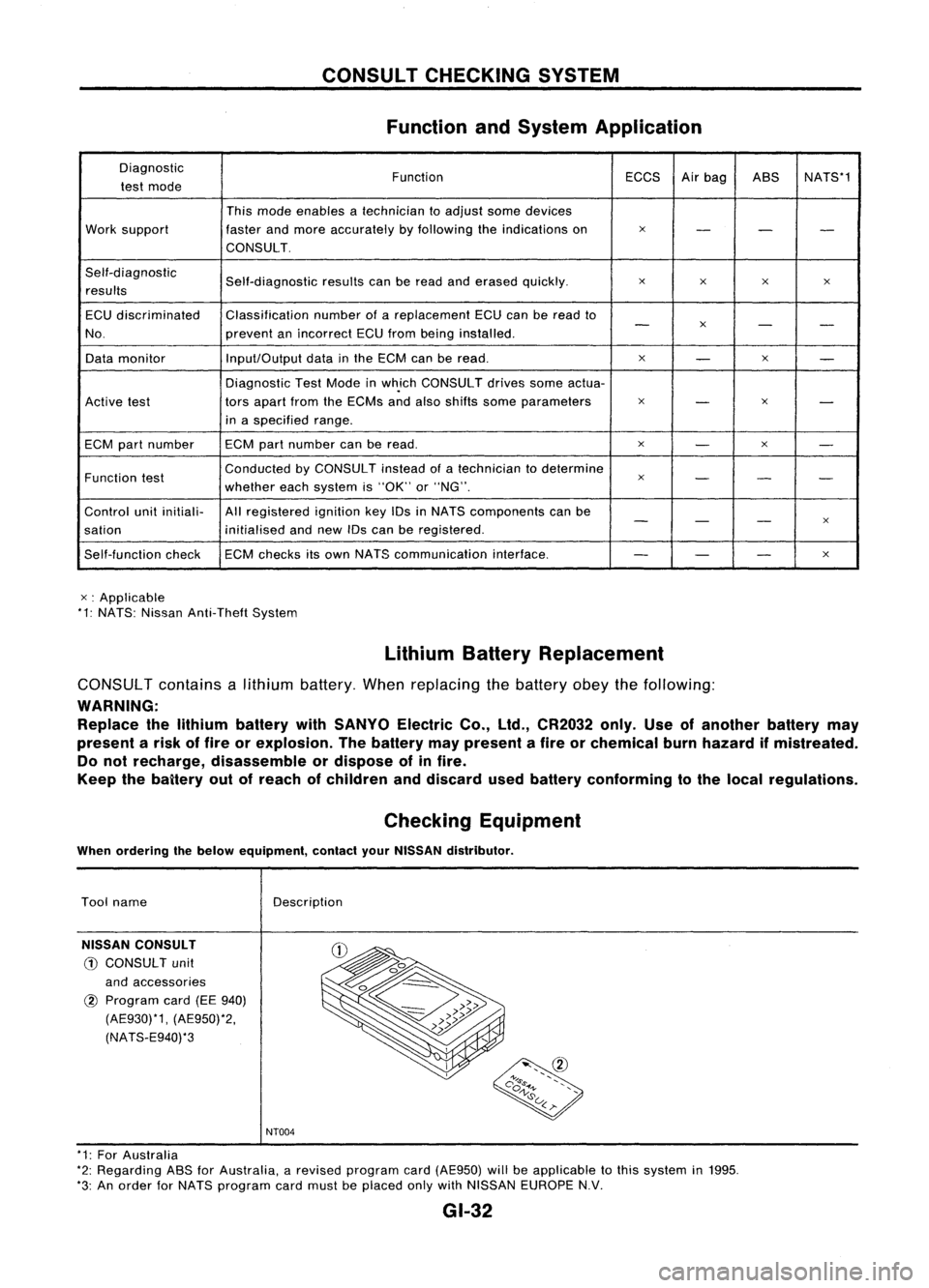
Function andSystem Application
Diagnostic FunctionECCSAirbag ASS NATS*1
test mode
Thismode enables atechnician toadjust somedevices
Work support fasterandmore accurately byfollowing theindications on
x
- --
CONSULT.
Self-diagnostic Self-diagnosticresultscanberead anderased quickly.
x
x x
x
results
ECU discriminated Classification
numberofareplacement ECUcanberead to
-
x
- -
No. preventanincorrect ECUfrom being installed.
Data monitor Input/Output
datainthe ECM canberead.
x
-
x
-
Diagnostic TestMode inwh.ich CONSULT drivessomeactua-
Active test tors
apart fromtheECMs andalso shifts some parameters
x
-
x
-
in aspecified range.
ECM partnumber ECM
partnumber canberead.
x
-
x
-
Function test Conducted
byCONSULT insteadofatechnician todetermine
x
- --
whether eachsystem is"OK" or"NG".
Control unitinitiali- Allregistered ignitionkeyIDsinNATS components canbe
- -
-
x
sation initialisedandnew IDscan beregistered.
Self-function checkECM
checks itsown NATS communication interface.
--
-
x
x :Applicable
*1: NATS: Nissan Anti-Theft System
LithiumBatteryReplacement
CONSUL Tcontains alithium battery. Whenreplacing thebattery obeythefollowing:
WARNING: Replace thelithium battery withSANYO ElectricCo.,ltd., CR2032 only.Useofanother batterymay
present arisk offire orexplosion. Thebattery maypresent afire orchemical burnhazard ifmistreated.
Do not recharge, disassemble ordispose ofinfire.
Keep thebaitery outofreach ofchildren anddiscard usedbattery conforming tothe local regulations.
Checking Equipment
When ordering thebelow equipment, contactyourNISSAN distributor.
Tool name
NISSAN CONSULT
CD
CONSULT unit
and accessories
@
Program card(EE940)
(AE930)*1, (AE950)*2,
(NATS-E940)*3 Description
NT004
* 1: For Australia
*2: Regarding ASSforAustralia, arevised program card(AE950) willbeapplicable tothis system in1995.
*3: An order forNATS program cardmust beplaced onlywithNISSAN EUROPE N.V.
GI-32