Page 615 of 1701
AUDIOANDANTENNA
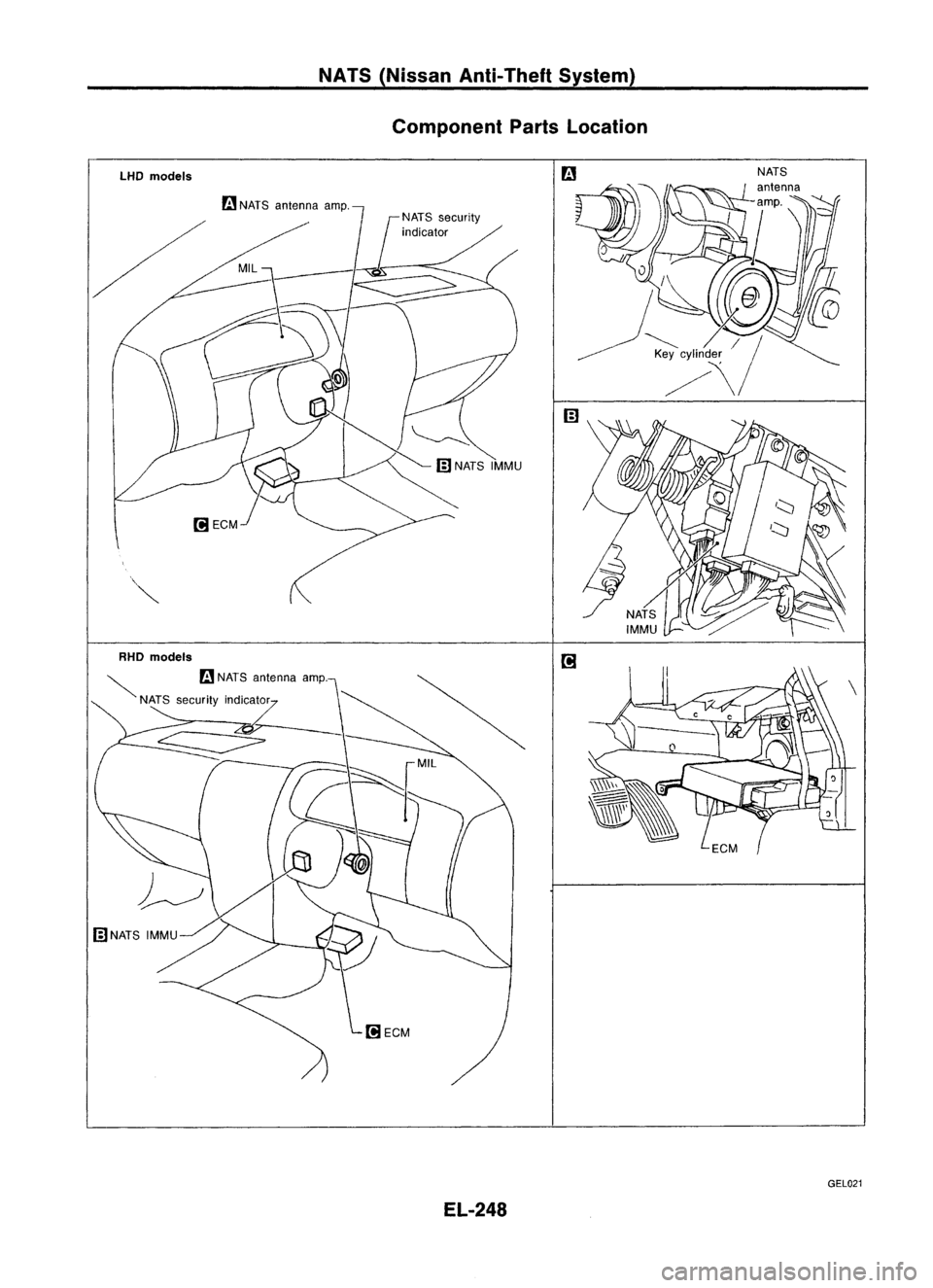
Antenna feeder
(RHO models) Radio
FuseCheck
Location ofAntenna
Antennafeeder
(LHO models)
Antenna RodReplacement
1. Loosen screwssecuring antennabase.
2. Pullout pipefrom antenna base.
Heating thepipe withadrier makes
it
easier.
EL-243 GEL020
•
Page 619 of 1701
NATS(Nissan Anti-Theft System)
System Description
NATS V2.0forNissan modelN15hasthefollowing immobiliser functions:
• Since onlyNATS ignition keys,whose IDnos. have been registered intotheECM andIMMU ofNATS,
allow theengine torun, operation ofastolen vehicle withoutaNATS registered keyisprevented by
NATS.
That isto say, NATS V2.0willimmobilize theengine ifsomeone triestostart itwithout theregis-
tered keyofNATS V2.0.
• Both ofthe originally suppliedignitionkeyIDshave been NATS registered.
If requested bythe vehicle owner,amaximum offour keyIDscan beregistered intotheNATS com-
ponents.
• The NATS security indicator (NATSsecurity ind.)blinks whentheignition switchisin "OFF" or
"ACC" position. Therefore, NATSwarns outsiders thatthevehicle isequipped withtheanti-theft
system.
• When NATSdetects trouble, themalfunction indicatorlamp(MIL) blinks.
• NATS trouble diagnoses, systeminitialisation andadditional registration ofother NATS ignition key
IDs must becarried outusing CONSULT hardwareandCONSULT NATSsoftware.
When NATS initialisation hasbeen completed, theIDofthe inserted ignitionkeyisautomatically
NATS registered. Then,ifnecessary, additionalregistration ofother NATS ignition keyIDscan be
carried out.
Regarding theprocedures ofNATS initialisation andNATS ignition keyIDregistration, refertoCON-
SUL Toperation manual,NATSV2.0.
• When diagnosing NATSV2.0using CONSULT, adapterandadapter harness forNATS V1.0arenot
necessary, althoughadirect DDLcable connection betweenCONSULT andDOL connector is
required.
• When servicing amalfunction ofthe NATS V2.0(indicated byflashing ofMalfunction IndicatorLamp)
or registering anotherNATSignition keyIDno., itmay benecessary tore-register originalkeyiden-
tification. Therefore, besure toreceive allkeys from vehicle owner.
System Composition
The immobiliser functionofthe NATS forNissan modelN15consists ofthe following:
• NATS ignition key
• NATS antenna amp.located inthe ignition keycylinder
• NATS immobiliser controlunit(NATS IMMU)
• Engine control module (ECM)
• NATS security indicator locatedunderthecenter cluster (NATSsecurity ind.)
• Malfunction indicatorlamp(MIL)
NATS ignition key
(
((
(
El-247
SEL304U
•
Page 620 of 1701
NATS(Nissan Anti-Theft System)
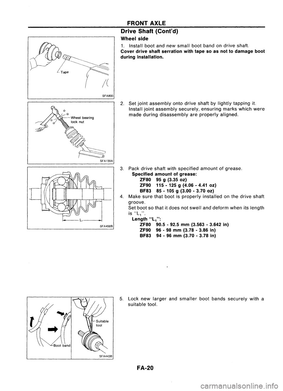
Component PartsLocation
LHO models
rn
NATS antenna amp.
RHO models
~ rn
NATS antenna amp.
NATS security indicator
EL-248 GEL021
Page 628 of 1701

NATS(Nissan Anti-Theft System)
Trouble Diagnoses (Cont'd)
SYMPTOM
SYSTEM REFERENCEPART Displayed"SELF- DIAGNOSTIC
PROCE-
(Malfunctioning NO.OFILLUSTRA-
•Blinking ofMIL*. •
Blinking ofMIL *.
DIAGRESULTS" on DURE
part ormode)
TIONONNEXT PAGE
•Engine willstart. •
Hard tostart
CONSULTscreen. (Reference
page)
engine.
System initialisation
has notyetbeen
F X
10
DISCORD, IMM- PROCEDURE 6
completed. ECM(EL-263)
ECM F X
Noise interference in
XMINGLE
NOISE PROCEDURE
7
communication line (EL-264)
Engine trouble data
DON'TERASE
and NATS trouble
BEFORECHECKING WORK
FLOW
data have been X
X
(EL-251)
detected inECM ENG
DIAG
SYMPTOM MATRIXCHART2
(Non self-diagnosis relateditem)
X:Possibility item
SYSTEM SYMPTOM
DIAGNOSTIC
PROCE-
(Malfunctioning partormode) DURE
NATS security indodoes notlight up.
(Referencepage)
NATS security indo
Open circuit between FuseandNATS IMMU
PROCEDURE8
X (EL-264)
Continuation ofinitialisation mode
NATS IMMU
DIAGNOSTIC SYSTEMDIAGRAM
NATS antenna amp.
PART
0 Key10chip (PART E5)
i-------
L---
--j)))
:
.
, ,
I~ .'
(((
NATS ignition
key
PART
E1,E2,E3, E4 IGN
PART C2~ +1./PART C1(MIL)
PART C4
ECM
..
........
................
:'
.......
PART F
D
IGN
EL-256
CONSULT
SEL466U
Page 636 of 1701
Self-diagnosticresults:
"MINGLE NOISE"displayed onCONSULT screen
m
T
Confirm SELF-DIAGNOSTIC RESULTS"MINGLENOISE"dis-
~ played onCONSULT screen.
NATS
(Nissan Anti-Theft System)
Trouble Diagnoses (Cont'd)
DIAGNOSTIC PROCEDURE 7
• SELF.DIAG RESULTS.
0
FAILURE DETECTED TIME
MINGLE NOISE 0
ERASE
II
PRINT
I
Turnofforremove anypossible noisesources.
SEL384U
• SELF.DIAG RESULTS.
0
FAILURE DETECTED TIME
MINGLE NOISE 0 Touch
"ERASE" onCONSULT SELF-DIAGNOSTIC RESULTS
screen.
ER~I PRINT
I
SEL385U
Start
engine.
OK
END
NG
DIAGNOSTIC PROCEDURE8
"NATS SECURITY IND.DOES NOTLIGHT UP"
m
o
UP
SIDE I~
....
EE3J
7.5A
SEL491U
Check
fuse(7.5A) inthe fuse box.
OK
NATS INITIALISATION
1) Fix the 7.5A fuseshown left
m.
2) Perform initialisation with
CONSULT.
For theoperation of
initialisation, referto"CON-
SUL Toperation manualNATS
V2.0".
NG
Replace fuse.
Turn ignition switch"OFF".
Start engine andturn ignition switch
"OFF".
Check NATSsecurity indoblinking.
OK
END
NG
EL-264
Page 637 of 1701
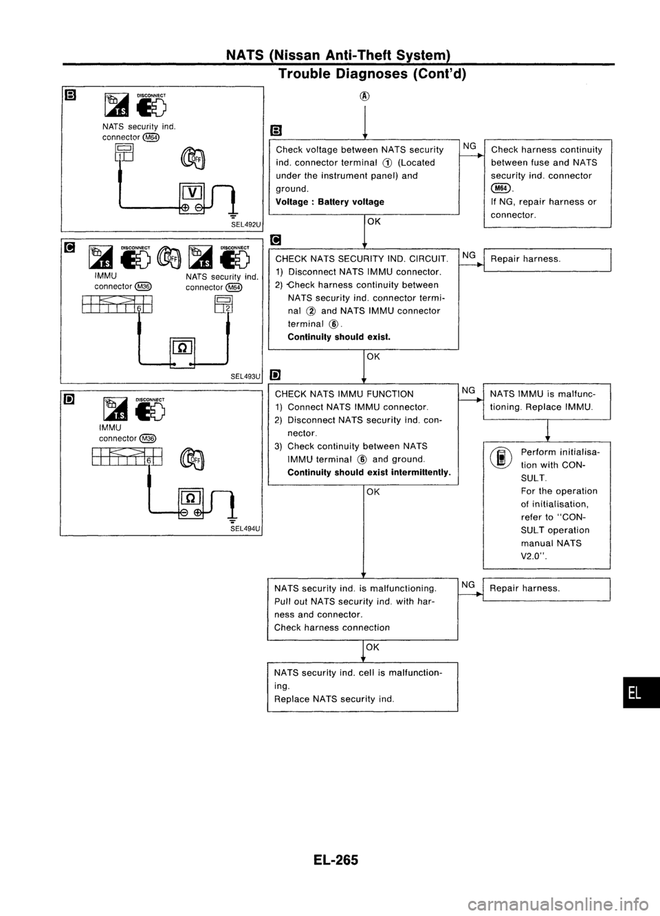
NATS(Nissan Anti-Theft System)
Trouble Diagnoses (Cont'd)
@
•
Ii)
Check voltage between NATSsecurity NG
Check harness continuity
indo connector terminal
G)
(Located
f------+
between fuseandNATS
under theinstrument panel)and securityindoconnector
ground.
@).
Voltage: Batteryvoltage
If
NG, repair harness or
connector .
OK
[!]
CHECK NATSSECURITY IND.CIRCUIT.
~Repair harness.
1) Disconnect NATSIMMU connector.
2) -Check harness continuity between
NATS security indoconnector termi-
nal @and NATS IMMUconnector
terminal
@.
Continuity shouldexist.
OK
IE
CHECK NATSIMMU FUNCTION NG
NATSIMMU ismalfunc-
1) Connect NATSIMMU connector.
-+
tioning. Replace IMMU.
2) Disconnect NATSsecurity indocon-
1
nector.
3)
Check
continuity betweenNATS
00
Perform
initialisa-
IMMU terminal
@
and ground.
tionwith CON-
Continuity shouldexistintermittently.
SULT.
OK For
theoperation
of initialisation,
refer to"CON-
SUL Toperation
manual NATS
V2.0".
NATS security indoismalfunctioning.
~Repair harness.
Pull outNATS security indowith har-
ness andconnector.
Check harness connection
OK
NATS security indocell ismalfunction-
ing.
Replace NATSsecurity indo
SEL494U
NATS
security indo
connector@
rQl
1 ~
DIJ ~
.".
SEL492U
[!]
~15c&a~15IMMU
NATSsecurity indo
connector@ connector~
EEFf,l1iE
~
[ID
SEL493U
IE
~15
IMMU
connector@
EEFfI1iili
~
EL-265
Page 702 of 1701
SFA800
r:r
1..--*
-Wheel bearing
lock nut
SFA130A
SFA4568
SFA4438
FRONT
AXLE
Drive Shaft(Cont'd)
Wheel side
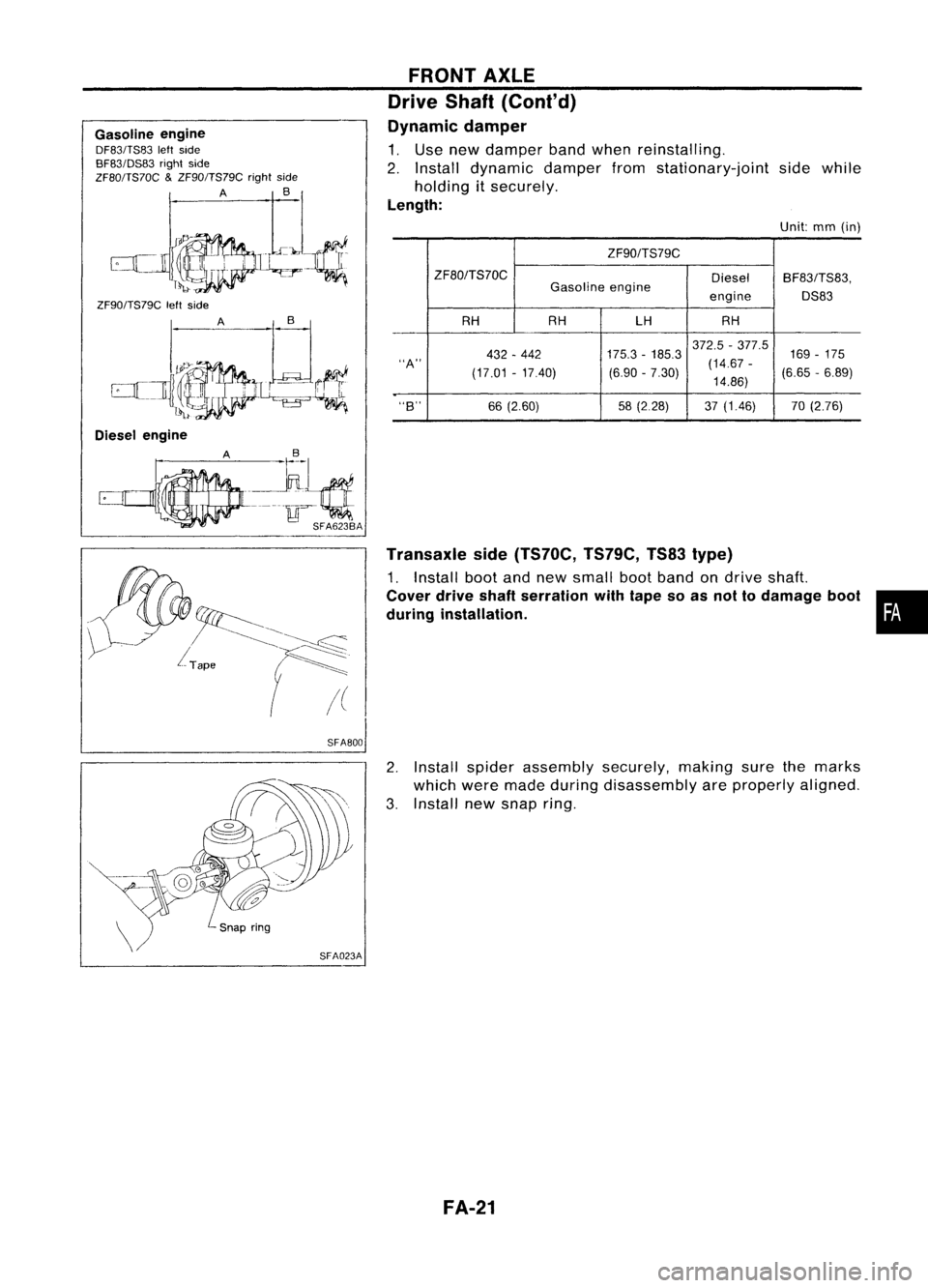
1. Install bootandnew small bootband on
drive
shaft.
Cover driveshaftserration withtape soas not todamage boot
during installation.
2. Set joint assembly onto
drive
shaftbylightly tapping it.
Install jointassembly securely,ensuringmarkswhichwere
made during disassembly areproperly aligned.
3. Pack
drive
shaftwithspecified amountofgrease.
Specified amountofgrease:
ZF80 95g(3.35
oz)
ZF90 115-125
g
(4.06 .4.41 oz)
BF83 85.105g(3.00 -3.70 oz)
4. Make surethatboot isproperly installedonthe drive shaft
groove.
Set boot sothat itdoes notswell anddeform whenitslength
is
"L,".
Length
"L/':
ZF80 90.5-92.5 mm(3.563 -3.642 in)
ZF90 96-98 mm (3.78 -3.86 in)
BF83 94-96 mm (3.70 -3.78 in)
5. Lock newlarger andsmaller bootbands securely witha
suitable tool.
FA-20
Page 703 of 1701
Gasolineengine
DF83/TS83 leftside
BF83/DS83 rightside
ZF80/TS70C
&
ZF90/TS79C rightside
A
B_1
.":JJ.Ci
ZF90/TS79C leftside
SFA800FRONT
AXLE
Drive Shaft(Cont'd)
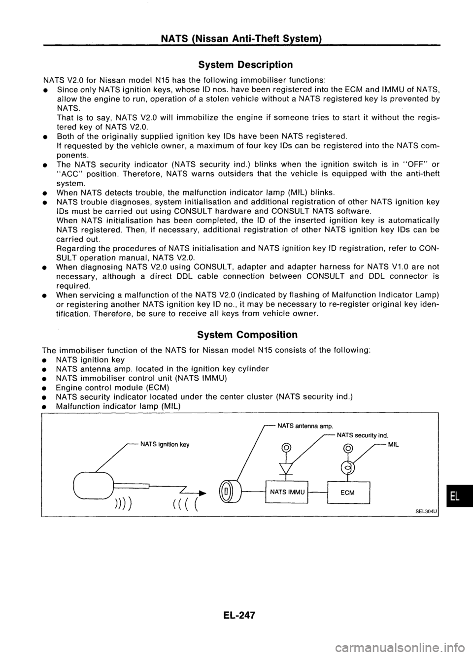
Dynamic damper
1. Use new damper bandwhen reinstalling.
2. Install dynamic damperfromstationary-joint sidewhile
holding itsecurely.
Length:
Unit:mm(in)
ZF90/TS79C
ZF80/TS70C DieselBF83/TS83,
Gasoline engine
engineDS83
RH RH LHRH
372.5 -377.5
169-175
432 -442 175.3
-185.3
"A"
(17.01-17.40) (6.90
-7.30) (14.67
-
(6.65-6.89)
14.86)
"B"
66(2.60) 58(2.28) 37(1.46) 70(2.76)
Transaxle side(TS70C, TS79C,TS83type)
1. Install bootandnew small bootband ondrive shaft.
Cover driveshaftserration withtape soas not todamage boot•
during installation.
2. Install spider assembly securely.makingsurethemarks
which weremade during disassembly areproperly aligned.
3. Install newsnap ring.
FA-21