Page 1175 of 1701
ENGINECOOLING SYSTEM
I
GA, SR,CD
I
Radiator (Aluminum type)
r
Sealing rubber~
•
SLC882AB
AIT
model only
r
Upper tank
Sealing rubber~
/"""-.
CJ~~ /~.........."-. '-.. ....,
1I
. / -~ '-""", /~Oil coolersecuring nut-
~ ~,>" (
6<,~8 •
12 N.m
(0.8•1.2 kg-m,
69-104
In-Ib)
@
0..~
~>..
!--Conicalwasher~
, ~I"~"-
Washer
/ /~, ,-O-ring~
Lower tank
-.I
I/' ,_
Oil cooler
o
,
SEC.
214
1.5(0.059)
H"
=
7.6
(0.299)
Unit: mm(in)
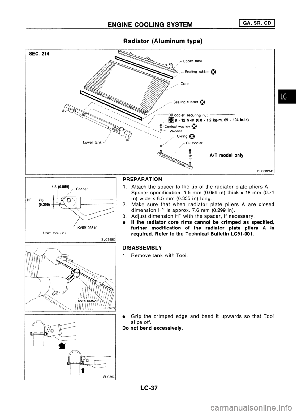
PREPARATION
1. Attach thespacer tothe tipofthe radiator platepliers A.
Spacer specification: 1.5mm (0.059 in)thick x18 mm (0.71
in) wide x8.5 mm (0.335 in)long.
2. Make surethatwhen radiator platepliers Aare closed
dimension H"isapprox. 7.6mm (0.299 in).
3. Adjust dimension H"with thespacer, ifnecessary.
• Ifthe radiator corerimscannot becrimped asspecified,
further modification ofthe radiator platepliers Ais
required. Refertothe Technical BulletinLC91-001.
SLC655C
D1SASSEMBL Y
1. Remove tankwithTool.
• Grip thecrimped edgeandbend itupwards sothat Tool
slips off.
Do not bend excessively.
*
LC-37
Page 1177 of 1701
SLC904
CD
@
10~~103~ \
~' ENGINE
COOLING SYSTEM
I
GA, SR,CD
I
Radiator (Aluminum type)(Cont'd)
4. Caulk tankinspecified sequence withTool.
•
Keep toolperpendicular to
the radiator.
o
X
(Grip isinsufficient.)
SLC896
• Use pliers inthe locations whereToolcannot beused.
5. Make surethattherim iscompletely crimpeddown.
Standard height
"H":
8.0 -8.4 mm (0.315 -0.331 in)
6. Confirm thatthere isno leakage.
Refer toInspection.
INSPECTION
Apply pressure withTool.
Specified pressurevalue:
157 kPa (1.57 bar,1.6kg/cm
2,
23psi)
WARNING:
To prevent therisk ofthe hose coming undonewhileunder
pressure, securelyfastenitdown withahose clamp.
Attach ahose tothe oilcooler aswell.
(A
IT models only)
SLC933 LC-39
Page 1217 of 1701
I
Recess
1
diameter
I
SEM795A CYLINDER
HEAD
Inspection (Cont'd)
VALVE SEATS
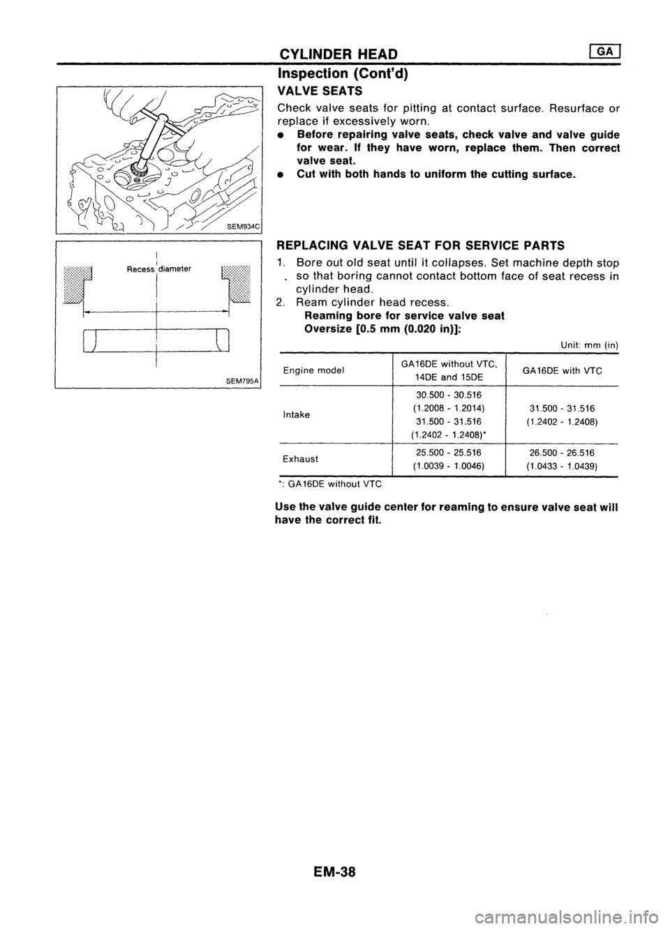
Check valveseats forpitting atcontact surface. Resurface or
replace ifexcessively worn.
• Before repairing valveseats, checkvalveandvalve guide
for wear. Ifthey have worn, replace them.Thencorrect
valve seat.
• Cut with both hands touniform thecutting surface.
REPLACING VALVESEATFORSERVICE PARTS
1. Bore outold seat until
it
collapses. Setmachine depthstop
so that boring cannot contact bottomfaceofseat recess in
cylinder head.
2. Ream cylinder headrecess.
Reaming boreforservice valveseat
Oversize [0.5mm(0.020 in)]:
Unit:mm(in)
Engine model GA16DE
withoutVTC,
GA16DE withVTC
14DE and15DE
30.500 -30.516
Intake (1.2008
-1.2014)
31.500-31.516
31.500 -31.516
(1.2402-1.2408)
(1.2402 -1.2408).
Exhaust 25.500
-25.516
26.500-26.516
(1.0039 -1.0046)
(1.0433-1.0439)
.: GA 16DE without VTC
Use thevalve guide center forreaming toensure valveseatwill
have thecorrect fit.
EM-38
Page 1236 of 1701

•
Front
Pistonringcompressor
SEM293C
2.
Install crankshaft andmain bearing capsandtighten bolts")
IdentificationNo.
\ca
p
\
NO.1
t.:?
Enginefront
SEM420C CYLINDER
BLOCK
Assembly (Cont'd)
•
Front
Pistonringcompressor
SEM293C
2.
Install crankshaft andmain bearing capsandtighten bolts
to the specified torque.
• Apply newengine oiltobolt threads andseat surface.
• Prior totightening bearingcapbolts, placebearing capin
its proper position byshifting crankshaft inthe axial direc-
tion.
• Tighten bearing capbolts gradually intwo orthree stages.
Start withcenter bearing andmove outward sequentially.
• After securing bearingcapbolts, makesurecrankshaft
turns smoothly byhand.
3. Measure crankshaft endplay.
Crankshaft endplay:
Standard:
0.060 -0.180 mm(0.0024 -0.0071 in)
Limit: 0.3 mm (0.012 in)
If beyond thelimit, replace thrustbearing witha
new one.
4. Install connecting rodbearings inconnecting rodsandcon-
necting rodcaps.
• Confirm thatcorrect bearings areused. Referto
"Inspection" (EM-52).
• Install bearings sothat oilhole inconnecting rodaligns with
oil hole ofbearing.
• Apply engine oiltobolt threads andbearing surfaces.
5. Install pistons withconnecting rods.
a. Install themintocorresponding cylinderswithTool.
• Becareful nottoscratch cylinder wallbyconnecting rod.
• Arrange sothat front mark onpiston headfaces toward
front ofengine.
• Apply engine oiltopiston ringsandsliding surface ofpis-
ton.
EM-57
Page 1270 of 1701
SEM083DCYLINDER
HEAD
Inspection (Cont'd)
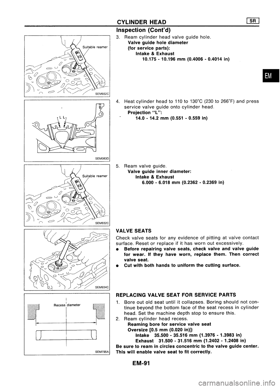
3. Ream cylinder headvalve guide hole.
Valve guide holediameter
(for service parts):
Intake
&
Exhaust
10.175 -10.196 mm(0.4006 -0.4014 in)
4. Heat cylinder headto110 to130°C (230to266°F) andpress
service valveguide ontocylinder head.
Projection
"L":
14.0 -14.2 mm(0.551 -0.559 in)
•
r
I
Recess
I
diameter
I
SEM795A
5.
Ream valveguide.
Valve guide innerdiameter:
Intake
&
Exhaust
6.000 -6.018 mm(0.2362 -0.2369 in)
VALVE SEATS
Check valveseatsforany evidence ofpitting atvalve contact
surface. Resetorreplace ifithas worn outexcessively.
• Before repairing valveseats, checkvalveandvalve guide
for wear. Ifthey have worn, replace them.Thencorrect
valve seat.
• Cut with both hands touniform thecutting surface.
REPLACING VALVESEATFORSERVICE PARTS
1. Bore outoldseat until
it
collapses. Boringshould notcon-
tinue beyond thebottom faceofthe seat recess incylinder
head. Setthemachine depthstoptoensure this.
2. Ream cylinder headrecess.
Reaming boreforservice valveseat
Oversize [0.5mm (0.020 in)]:
Intake 35.500-35.516 mm(1.3976 -1.3983 in)
Exhaust 31.500.31.516 mm(1.2402 -1.2408 in)
Be sure toream incircles concentric tothe valve guide center.
This willenable valveseattofit correctly.
EM-91
Page 1290 of 1701
![NISSAN ALMERA N15 1995 Service Manual Tighteninnumerical order.
'::::::-.... Alignoilhole.
~~
'~~-
SEM015D
SEM159B CYLINDER
BLOCK [][]
Assembly (Cont'd)
2. Install crankshaft andmain bearing capsandtighten bolts
to the spec](/manual-img/5/57349/w960_57349-1289.png "NISSAN ALMERA N15 1995 Service Manual Tighteninnumerical order.
'::::::-.... Alignoilhole.
~~
'~~-
SEM015D
SEM159B CYLINDER
BLOCK [][]
Assembly (Cont'd)
2. Install crankshaft andmain bearing capsandtighten bolts
to the spec")
Tighteninnumerical order.
'::::::-.... Alignoilhole.
~~
'~~-
SEM015D
SEM159B CYLINDER
BLOCK [][]
Assembly (Cont'd)
2. Install crankshaft andmain bearing capsandtighten bolts
to the specified torque.
• Apply newengine oiltothread ofbearing capbolts.
• Prior totightening bearingcapbolts, shiftcrankshaft back
and forth toproperly seatthebearing cap.
• Tightening procedure
a. Tighten allbolts to26 to32 N'm (2.7to3.3 kg-m, 20to24 •
in-Ib).
b. Turn allbolts 75to80 degrees clockwise withTool orsuit-
able angle wrench.
c. Loosen allbolts completely.
d. Tighten allbolts to32 to38 N'm (3.3to3.9 kg-m, 24to28
ft-Ib).
e. Turn allbolts 45to50 degrees clockwise withTool orsuit-
able angle wrench.
• Ifan angle wrench isnot available, markallbearing cap
bolts onthe side facing engine rear.Then, turneach bolt
specified degreesclockwise. Confirmangleofdegrees with
a graduator, notbyeye-measurement.
• After securing bearingcapbolts, makesurecrankshaft
turns smoothly byhand.
3. Measure crankshaft endplay.
Crankshaft endplay:
Standard
0.10 -0.26 mm(0.0039 -0.0102 in)
Limit
0.30 mm(0.0118 in)
If beyond thelimit, replace thrustbearings withnewones.
4. Install connecting rodbearings inconnecting rodsandcon-
necting rodcaps.
• Confirm thatcorrect bearings areused. Referto
"I nspection" .
• Install bearings sothat oilhole inconnecting rodaligns with
oil hole ofbearing.
• Apply newengine oiltobolt threads andbearing surfaces.
5. Install pistons withconnecting rods.
a. Install themintocorresponding cylinderswithTool.
• Becareful nottoscratch cylinder wallbyconnecting rod.
• Arrange sothat front mark onpiston headfaces toward
front ofengine.
• Apply newengine oiltopiston ringsandsliding surface of
piston.
EM-111
Page 1300 of 1701
SEM520DSEM515D TIMING
BELT
em
Camshaft TimingBelt(Cont'd)
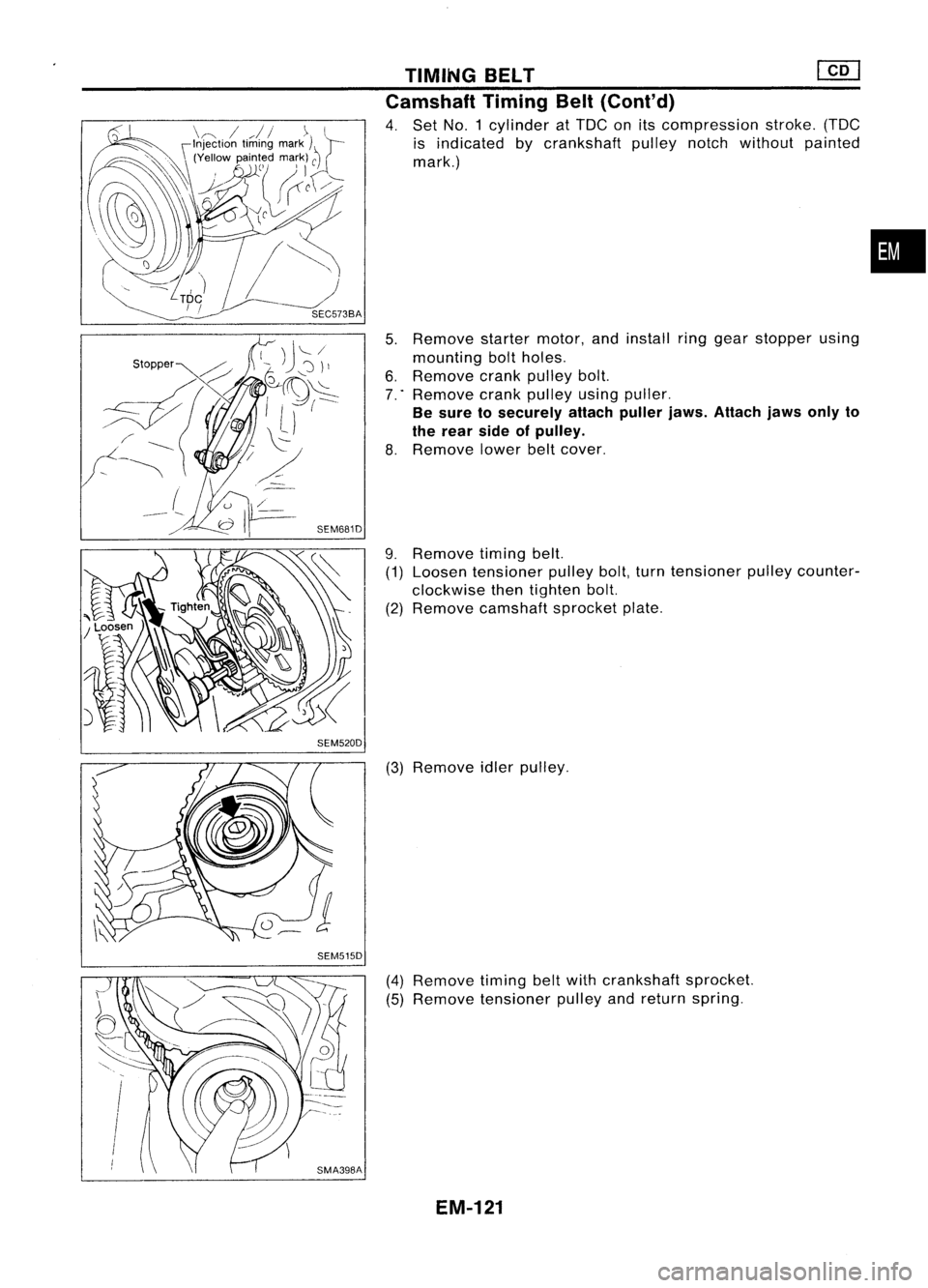
4. Set NO.1 cylinder atTDC onitscompression stroke.(TDC
is indicated bycrankshaft pulleynotchwithout painted
mark.)
5. Remove startermotor,andinstall ringgear stopper using
mounting boltholes.
6. Remove crankpulley bolt.
7 .. Remove crankpulley usingpuller.
Be sure tosecurely attachpullerjaws.Attach jawsonlyto
the rear sideofpulley.
8. Remove lowerbeltcover.
9. Remove timingbelt.
(1) Loosen tensioner pulleybolt,turntensioner pulleycounter-
clockwise thentighten bolt.
(2) Remove camshaft sprocketplate.
(3) Remove idlerpulley.
(4) Remove timingbeltwith crankshaft sprocket.
(5) Remove tensioner pulleyandreturn spring.
EM-121
•
Page 1303 of 1701
![NISSAN ALMERA N15 1995 Service Manual TIMINGBELT
@[]
Camshaft TimingBelt(Cont'd)
5. Install timing beltwith crankshaft sprocket.
a. Align white linesontiming beltwith punchmarks oncam-
shaft sprocket andcrankshaft sprocket.
b. Poi](/manual-img/5/57349/w960_57349-1302.png "NISSAN ALMERA N15 1995 Service Manual TIMINGBELT
@[]
Camshaft TimingBelt(Cont'd)
5. Install timing beltwith crankshaft sprocket.
a. Align white linesontiming beltwith punchmarks oncam-
shaft sprocket andcrankshaft sprocket.
b. Poi")
TIMINGBELT
@[]
Camshaft TimingBelt(Cont'd)
5. Install timing beltwith crankshaft sprocket.
a. Align white linesontiming beltwith punchmarks oncam-
shaft sprocket andcrankshaft sprocket.
b. Point arrow ontiming belttoward beltcover.
6. Install camshaft sprocketplateandsecure screws withlock-
tite.
7. Adjust timing belttension.
1) Loosen tensioner lockbolttoapply tension totiming belt.
2) Rotate crankshaft clockwisetwoturns toapply thespecified
tension totiming belt.
3) Tighten tensioner lockboltwhile holding tensioner pUlley
with hexagon wrench. .
Belt tension:
147.1 :1:24.5 N(15:1:2.5 kg,33.1 :1:5.5 Ib)
SEM520D Injection PumpTiming Belt
~ .N'm (kg-m, in-Ib)
~ :N.m (kg-m, ft-Ib)
SEC.
130-135
~
-"~
.~\(~[-~~' c~1
Timingbelt
?\~-d
(~K.
c
'0
t£
Tensioner spring
J
J
N
0~lJ'00 ~/ Tensioner
t0
J
l\J~.~l:~
'Gl
~')U
r
r~/~
16-21 (1.6 -2.1,12 -15)
It
I
L~0--~ '
~htiJ
JD/~h~J/ "
'SP/
_-z,}) ~A
[/ ......., ....... InJeclion~
.... ~. -;;, pump@J_
• '~~ sprocket~
"fc;,~~-
@ ~
59-
69-.1
Rear camshaft sprocket .~(6.0•7.0,
1m
43-51)
[O;l
87•107
(8.9 -10.9, 64•79)
SEM225F
REMOVAL
1. Set NO.1 cylinder atTDC onitscompression stroke.(TDC
is indicated bycrankshaft pulleynotchwithout painted
mark.)
2. Remove airduct withresonator andtiming beltcover.
EM-124
(Cont'd)
4. Caulk tankinspecified sequence withTool.
•
Keep toolperpendicular to
the radiator.")