Page 918 of 1701
TROUBLEDIAGNOSIS FORNON-DETECTABLE ITEMS
Valve Timing Control (VTC)(Cont'd)
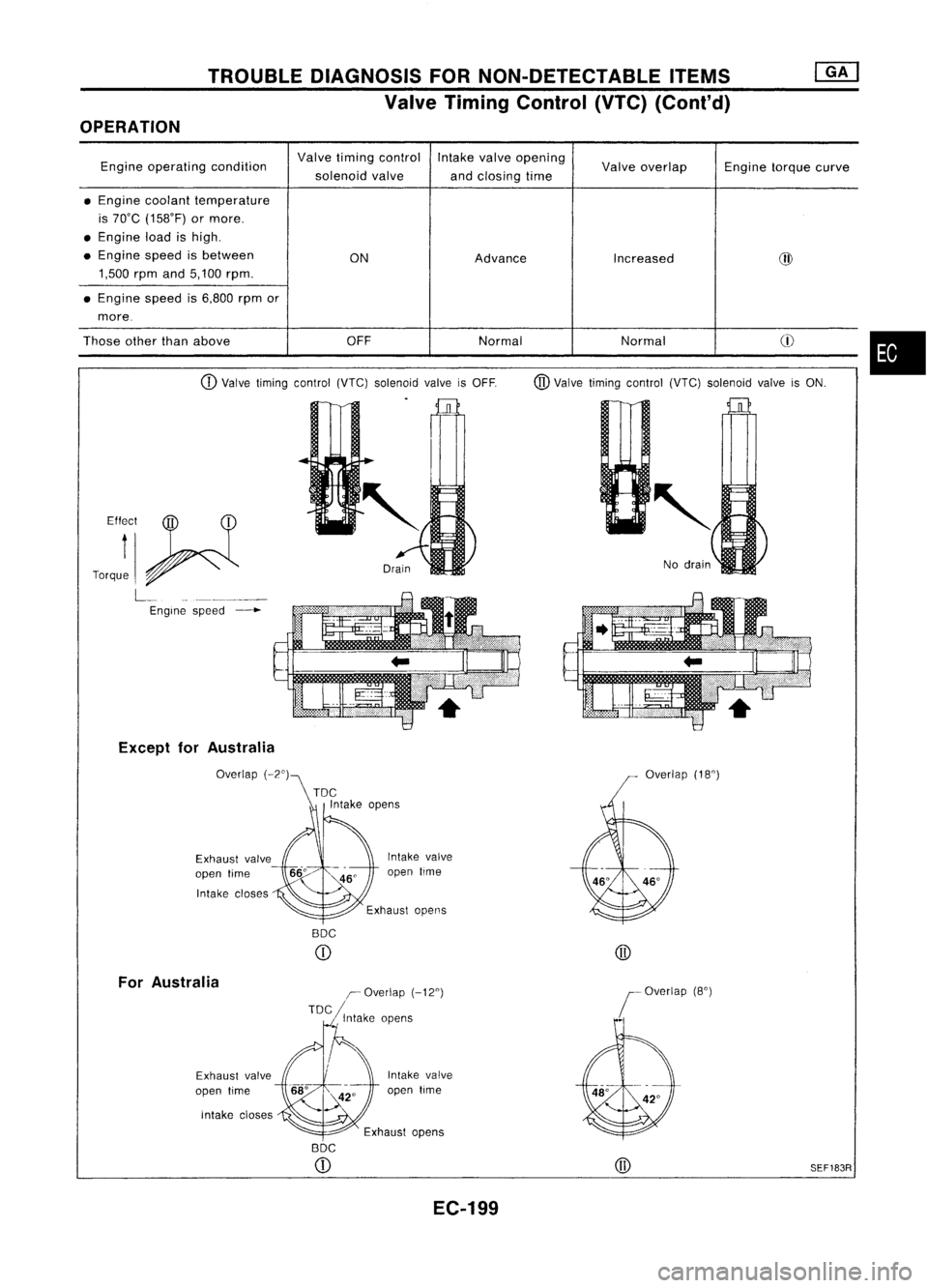
OPERATION
Engine operating condition Valve
timing control Intakevalveopening
Valveoverlap Enginetorquecurve
solenoid valve
andclosing time
• Engine coolant temperature
is 70"C (158"F) ormore .
• Engine loadishigh .
• Engine speedisbetween
ONAdvance
Increased @
1,500 rpmand5,100 rpm.
• Engine speedis6,800 rpmor
more.
Those otherthanabove OFFNormal Normal
CD
CD
Valve timing control (VTC)solenoid valveisOFF. @Valve timing control (VTC)solenoid valveisON.
•
Effr
t
f__ ~
Torque ~
L__ _
Engine speed
--+-
Except forAustralia
Exhaust valve
open time
Intake closes
For Australia
Exhaust valve
open time
intake cioses Intake
valve
open lime
BOC
CD
I~Overlap (-12°)
TOC ,Intake opens
Intake valve
open time Overlap
(18°)
@
BOC
CD
EC-199 @
SEF183R
Page 964 of 1701
AEC804
•
Ii
L
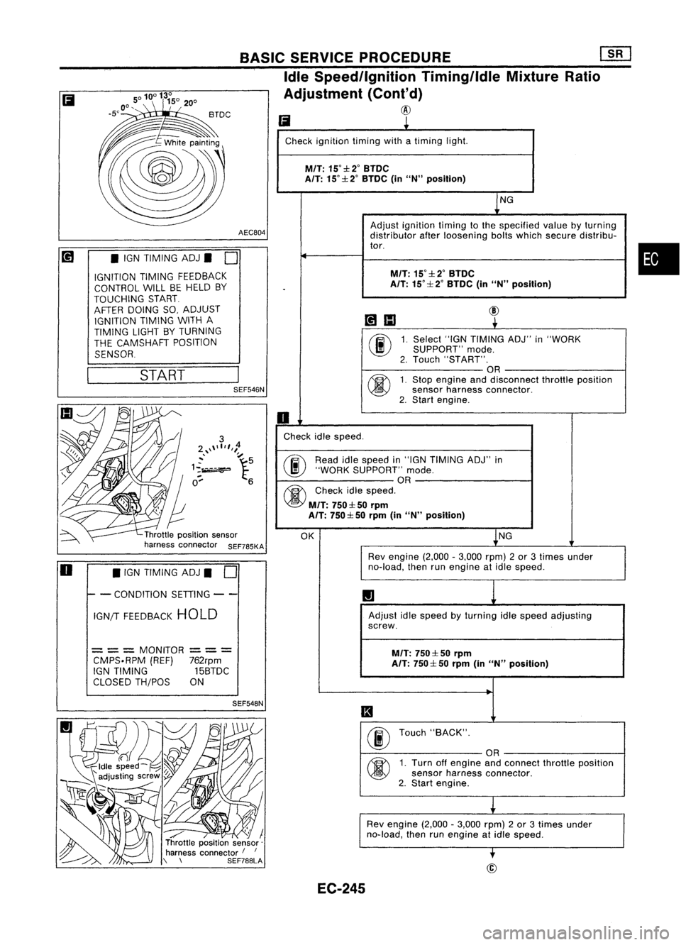
Check ignition timingwithatiming light.
M/T:
15°::l:2°BTDC
A/T: 15°::l: 2°BTDC (inUN" position)
NG
Adjust ignition timingtothe specified valuebyturning
distributor afterloosening boltswhich secure distribu-
tor.
M/T:
15°::l:2°BTDC
.
A/T:
15°::l: 2°BTDC (inUN" position)
~IIJ
@
~
00
1.
Select
"IGNTIMING ADJ"in"WORK
SUPPORT" mode.
2. Touch "START".
OR
@
1.
Stop engine anddisconnect throttleposition
sensor harness connector.
2. Start engine.
0
Check idlespeed.
@ Read
idlespeed in"IGN TIMING ADJ"in
"WORK SUPPORT" mode.
OR
@
Checkidlespeed.
M/T:
750::l: 50rprn
A/T: 750::l: 50rprn (inUN" position)
OK NG
Rev engine (2,000-3,000 rpm)2or 3times under
no-load, thenrunengine atidle speed.
1.1
Adjust idlespeed byturning idlespeed adjusting
screw.
M/T:
750::l: 50rpm
A/T: 750::l: 50rprn (inUN" position)
II
00
Touch
"BACK".
OR
@
1.
Turn offengine andconnect throttleposition
sensor harness connector.
2. Start engine.
L
Rev engine (2,000-3,000 rpm)2or 3times under
no-load, thenrunengine atidle speed.
-.
BASIC
SERVICE PROCEDURE
[]K]
Idle Speed/Ignition Timing/IdleMixtureRatio
Adjustment (Cont'd)
@
SEF548N
/ / I
Throttle position sensor-
harness connector /
I
\ \ SEF788LASEF546N
START
•
IGN TIMING ADJ.
0
IGNITION TIMINGFEEDBACK
CONTROL WILLBEHELD BY
TOUCHING START
AFTER DOING SO,ADJUST
IGNITION TIMINGWITHA
TIMING LIGHTBYTURNING
THE CAMSHAFT POSITION
SENSOR
= ==
MONITOR
==
=
CMPS.RPM (REF)762rpm
IGN TIMING 15BTDC
CLOSED TH/POS ON
Ii
o •
IGN TIMING ADJ.
0
I- -
CONDITION SETIING--
IGN/T FEEDBACK HOLD
EC-245
Page 983 of 1701

TROUBLEDIAGNOSIS -General Description
Sensors
~ ECMActuators
~~.~ MEF036D
SEF234G Introduction
The engine hasanECM tocontrol majorsystems suchasfuel
control, ignitioncontrol, idleaircontrol system, etc.The ECM
accepts inputsignals fromsensors andinstantly drivesactua-
tors. Itis essential thatboth input andoutput signals areproper
and stable. Atthe same time,itis important thatthere areno
problems suchasvacuum leaks,fouled sparkplugs, orother
problems withtheengine.
It is much moredifficult todiagnose aproblem thatoccurs
intermittently ratherthancontinuously. Mostintermittent prob-
lems arecaused bypoor electric connections orimproper wir-
ing. Inthis case, careful checking ofsuspected circuitsmay
help prevent thereplacement ofgood parts.
A visual checkonlymaynotfind thecause ofthe problems. A
road testwith CONSULT oracircuit testerconnected shouldbe
performed. Followthe"Work Flow"onthe next page.
Before undertaking actualchecks, takejustafew minutes to
talk with acustomer whoapproaches withadriveability com-
plaint. Thecustomer cansupply goodinformation aboutsuch
problems, especially intermittent ones.Findoutwhat symptoms
are present andunder whatconditions theyoccur. A"Diagnos-
tic Worksheet" liketheexample onEC-267 shouldbeused.
Start yourdiagnosis bylooking for"conventional" problems
first. Thiswillhelp troubleshoot driveabilityproblemsonan
electronically controlledenginevehicle.
EC-264
Page 1093 of 1701
VE-TYPE INJECTION PUMP
SEF779A
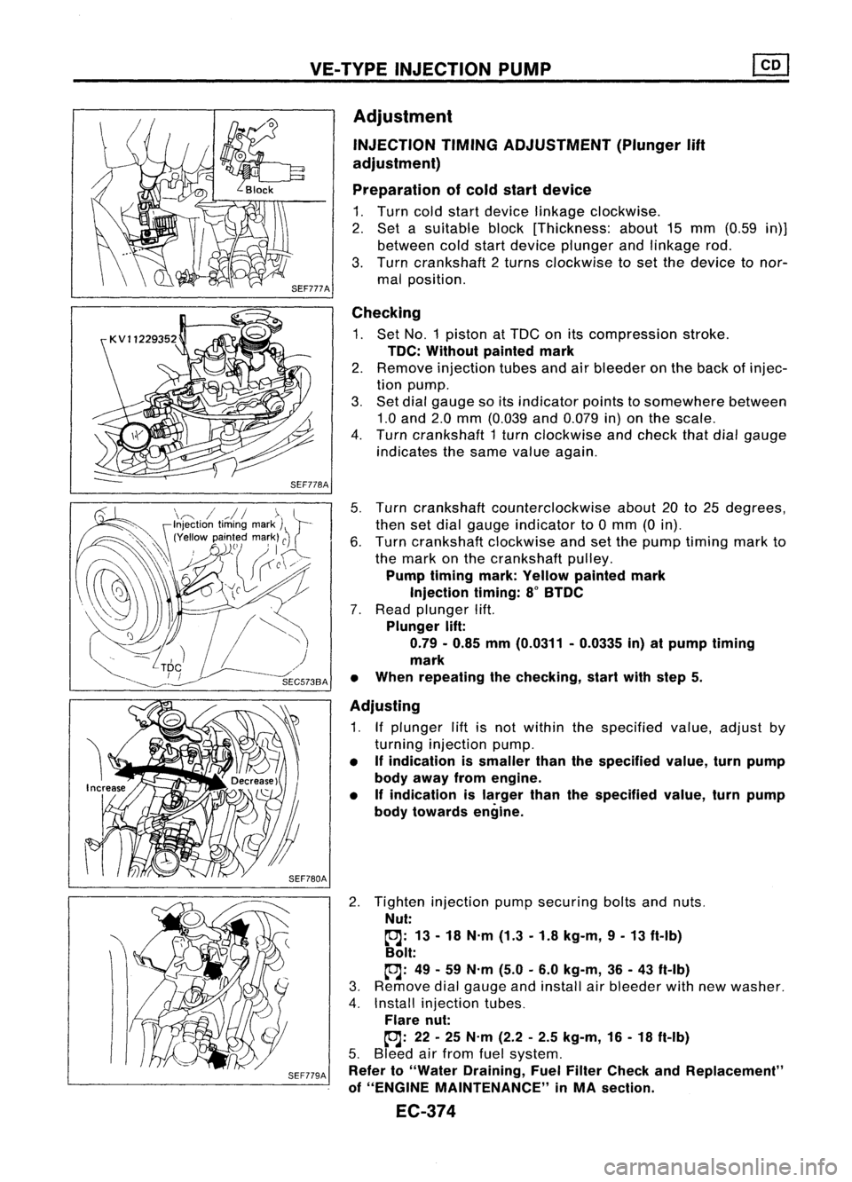
Adjustment
INJECTION TIMINGADJUSTMENT (Plunger
lift
adjustment)
Preparation ofcold start device
1. Turn coldstart device linkage clockwise.
2. Set asuitable block[Thickness: about15mm (0.59 in)]
between coldstart device plunger andlinkage rod.
3. Turn crankshaft 2turns clockwise toset the device tonor-
mal position.
Checking
1. Set NO.1 piston atTDC onitscompression stroke.
TDC: Without paintedmark
2. Remove injection tubesandairbleeder onthe back ofinjec-
tion pump.
3. Set dial gauge soitsindicator pointstosomewhere between
1.0 and 2.0mm (0.039 and0.079 in)onthe scale.
4. Turn crankshaft 1turn clockwise andcheck thatdialgauge
indicates thesame value again.
5. Turn crankshaft counterclockwise about20to25 degrees,
then setdial gauge indicator to0mm (0in).
6. Turn crankshaft clockwiseandsetthe pump timing markto
the mark onthe crankshaft pulley.
Pump timing mark:Yellow painted mark
Injection timing:8
0
BTDC
7. Read plunger lift.
Plunger lift:
0.79 -0.85 mm(0.0311 -0.0335 in)atpump timing
mark
• When repeating thechecking, startwithstep 5.
Adjusting
1. Ifplunger liftisnot within thespecified value,adjust by
turning injection pump.
• Ifindication issmaller thanthespecified value,turnpump
body away fromengine.
• Ifindication islarger thanthespecified value,turnpump
body towards engine.
2. Tighten injection pumpsecuring boltsandnuts.
Nut:
~: 13-18 N.m (1.3-1.8 kg-m, 9-13 ft-Ib)
Bolt:
~: 49-59 N.m (5.0-6.0 kg-m, 36-43 ft-Ib)
3. Remove dialgauge andinstall airbleeder withnewwasher.
4. Install injection tubes.
Flare nut:
~: 22-25 N.m (2.2-2.5 kg-m, 16-18 ft-Ib)
5. Bleed airfrom fuelsystem.
Refer to"Water Draining, FuelFilter Check andReplacement"
of "ENGINE MAINTENANCE" inMA section.
EC-374
Page 1094 of 1701
VE-TVPEINJECTION PUMP ~
Adjustment (Cont'd)
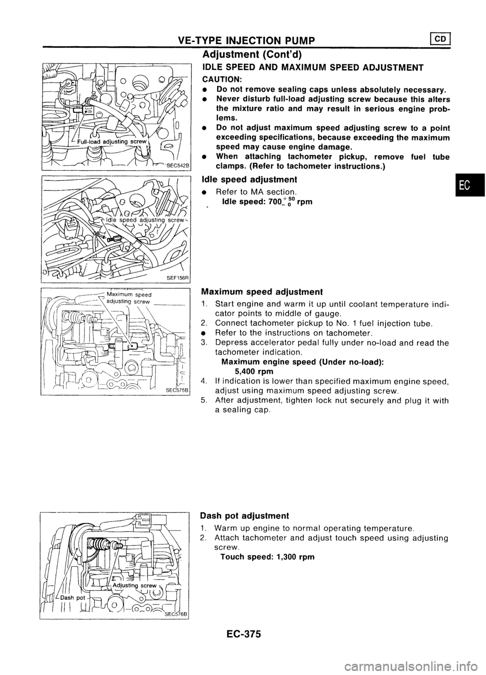
IDLE SPEED ANDMAXIMUM SPEEDADJUSTMENT
CAUTION:
• Donot remove sealingcapsunless absolutely necessary.
• Never disturb full-load adjusting screwbecause thisalters
the mixture ratioandmay result inserious engineprob-
lems.
• Donot adjust maximum speedadjusting screwtoapoint
exceeding specifications, becauseexceeding themaximum
speed maycause engine damage.
• When attaching tachometer pickup,remove fueltUbe
clamps. (Refertotachometer instructions.)
Idle speed adjustment •
• Refer toMA section.
Idle speed:
700~
~o
rpm
SEF156R Maximum speedadjustment
1. Start engine andwarm itup until coolant temperature indi-
cator points tomiddle ofgauge.
2. Connect tachometer pickuptoNO.1 fuelinjection tube.
• Refer tothe instructions ontachometer.
3. Depress accelerator pedalfullyunder no-load andread the
tachometer indication.
Maximum enginespeed(Under no-load):
5,400 rpm
4.
If
indication islower thanspecified maximum enginespeed,
adjust usingmaximum speedadjusting screw.
5. After adjustment, tightenlocknutsecurely andplug itwith
a sealing cap.
Dash potadjustment
1. Warm upengine tonormal operating temperature.
2. Attach tachometer andadjust touchspeed usingadjusting
screw.
Touch speed: 1,300rpm
EC-375
Page 1117 of 1701
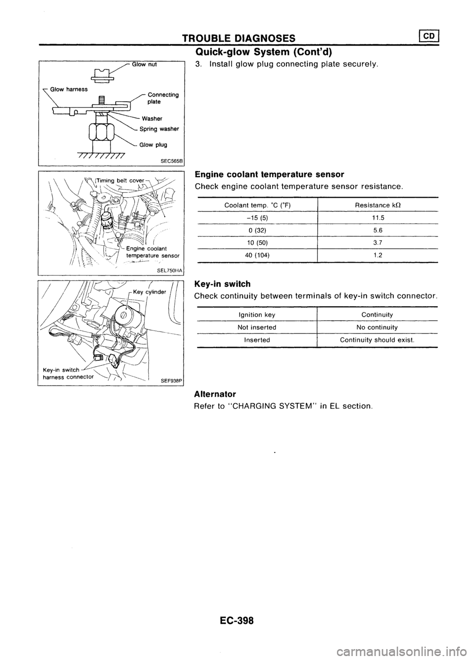
SEC5658Enginecoolant temperature sensor
Check engine coolant temperature sensorresistance.
Key-in switch
Check continuity betweenterminals ofkey-in switch connector.
11.5
5.6
3.7
1.2
Resistance
kfl
Continuity
No continuity
Continuity shouldexist.
Ignition
key
Not inserted
Inserted
Coolant
temp.°C('F)
-15 (5)
0(32)
10 (50)
40 (104)
TROUBLE
DIAGNOSES
Quick-glow System(Cont'd)
3. Install glowplugconnecting platesecurely.
Connecting
plate
Spring washer
~GIOwnut
Glow harness
Alternator
Refer to"CHARGING SYSTEM"inEL section.
EC-398
Page 1151 of 1701
ENGINECOOLING SYSTEM
IiJ
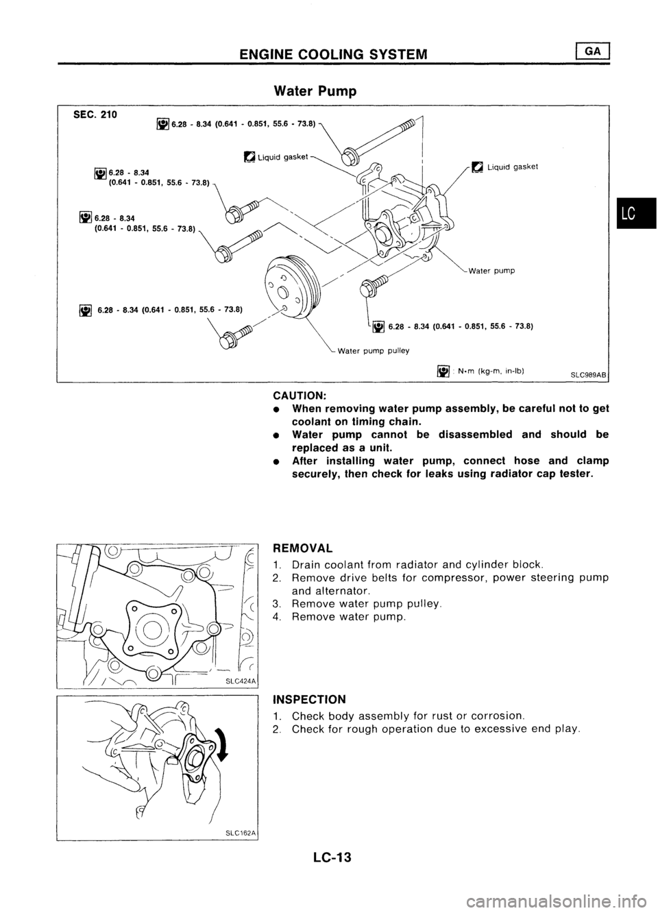
6.28 -8.34 (0.641 -0.851, 55.6-73.8)
SEC.
210 Water
Pump
~ 6.28 -8.34 (0.641 -0.851, 55.6-73.8)
WaterpumppUlley
l
~Liquid gasket
~ N.m(kg-m, in-Ib)
SLC989AB
•
CAUTION:
• When removing waterpumpassembly, becareful nottoget
coolant ontiming chain.
• Water pumpcannot bedisassembled andshould be
replaced asaunit.
• After installing waterpump, connect hoseandclamp
securely, thencheck forleaks using radiator captester.
REMOVAL
1. Drain coolant fromradiator andcylinder block.
2. Remove drivebeltsforcompressor, powersteering pump
and alternator.
3. Remove waterpumppulley.
4. Remove waterpump.
INSPECTION
1. Check bodyassembly forrust orcorrosion.
2. Check forrough operation duetoexcessive endplay.
SLC162A LC-13
Page 1160 of 1701
A16-21
N.m ~/
(1.6 •2.1 kg-m,
12 -15
ft.lb)
ENGINE
COOLING SYSTEM
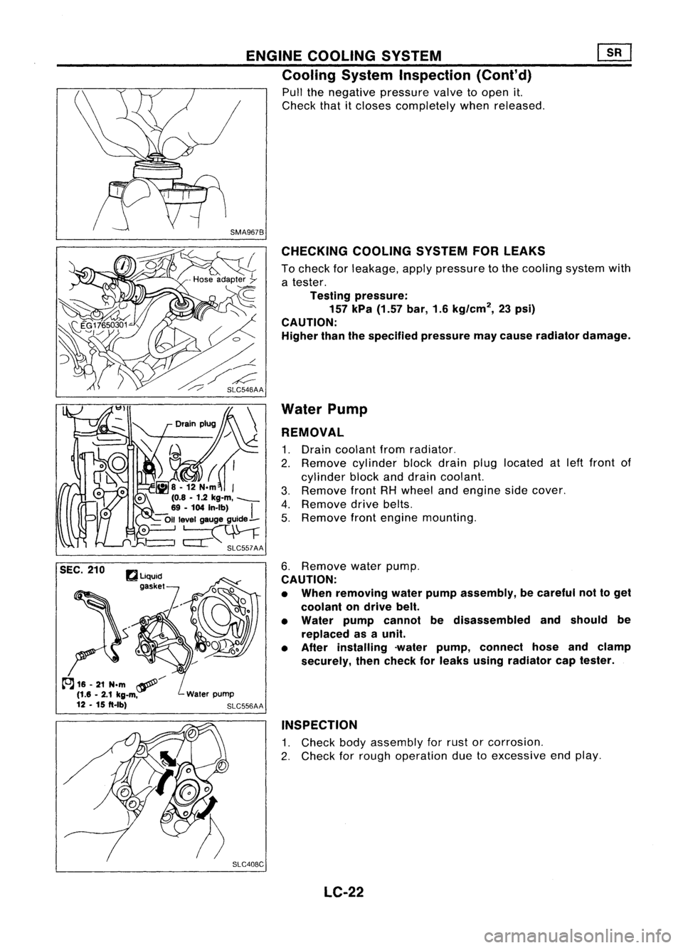
Cooling SystemInspection (Cont'd)
Pull thenegative pressure valvetoopen it.
Check thatitcloses completely whenreleased.
CHECKING COOLINGSYSTEMFORLEAKS
To check forleakage, applypressure tothe cooling systemwith
a tester.
Testing pressure:
157 kPa (1.57 bar,1.6kg/cm
2,
23psi)
CAUTION:
Higher thanthespecified pressuremaycause radiator damage.
Water Pump
REMOVAL
1. Drain coolant fromradiator.
2. Remove cylinderblockdrain pluglocated atleft front of
cylinder blockanddrain coolant.
3. Remove frontRHwheel andengine sidecover.
4. Remove drivebelts.
5. Remove frontengine mounting.
6. Remove waterpump.
CAUTION:
• When removing waterpumpassembly, becareful nottoget
coolant ondrive belt.
• Water pumpcannot bedisassembled andshould be
replaced asaunit.
• After installing -waterpump, connect hoseandclamp
securely, thencheck forleaks using radiator captester.
INSPECTION
1. Check bodyassembly forrust orcorrosion.
2. Check forrough operation duetoexcessive endplay.
SLC408C LC-22