Page 244 of 1701
INTERIORTRIM
Roof Trim
REMOVAL -Headlining
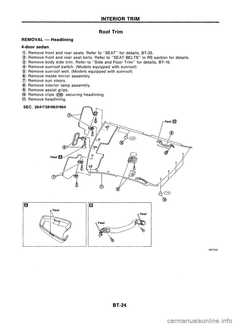
4-door sedan
CD
Remove frontandrear seats. Referto"SEAT" fordetails, BT-35.
@
Remove frontandrear seat belts. Referto"SEAT BELTS" inRS section fordetails.
@)
Remove bodysidetrim. Refer to"Side andFloor Trim" fordetails, BT-16.
@
Remove sunroofswitch.(Models equipped withsunroof)
@
Remove sunroofwelt.(Models equipped withsunroof)
@
Remove insidemirror assembly.
([) Remove sunvisors.
@
Remove interiorlampassembly.
@
Remove assistgrips.
@)
Remove clips
@
securing headlining.
@
Remove headlining.
SEC. 264-738-963-964
9
Pawl'
Pawl SBT056
BT-24
Page 245 of 1701
INTERIORTRIM
Roof Trim (Cont'd)
REMOVAL -Headlining
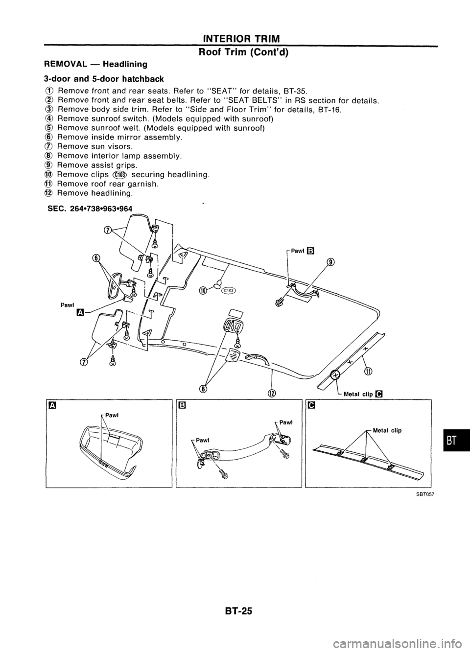
3-door and5-door hatchback
CD
Remove frontandrear seats. Referto"SEAT" fordetails, BT-35.
@
Remove frontandrear seat belts. Referto"SEAT BELTS" inRS section fordetails.
@)
Remove bodysidetrim. Refer to"Side andFloor Trim" fordetails, BT-16.
@
Remove sunroofswitch.(Models equipped withsunroof)
cID
Remove sunroofwelt.(Models equipped withsunroof)
@
Remove insidemirror assembly.
(f)
Remove sunvisors.
@
Remove interiorlampassembly.
@
Remove assistgrips.
@)
Remove clips
@
securing headlining.
(j]
Remove roofrear garnish.
@
Remove headlining.
SEC.
264-738-963-964
Pawl
•
Metal
clip
l!1
Pawlm
m
SBT05?
8T-25
Page 263 of 1701
WINDSHIELDANDWINDOWS
Cutting sealant
SBF034BREMOVAL
After removing moldings, removeglass,
CAUTION: Be careful nottoscratch glasswhen removing.
INSTALLATION
• Use genuine NissanSealant kitorequivalent. Follow
instructions furnishedwithit.
• After installing theglass, thevehicle shouldremain station-
ary until thesealant hardens.
WARNING: Keep heatandopen flames awayasprimers areflammable.
CAUTION:
Advise usernottodrive thevehicle onrough roadsuntilseal-
ant has properly vulcanized.
•. Donot use sealant whichispast itsusable term.
• Donot leave cartridge unattended withitscap open.
• Keep primers andsealant inacool, dryplace. Ideally, they
should bestored inarefrigerator.
• Molding mustbeinstalled securely sothat itis in position
and leaves nogap.
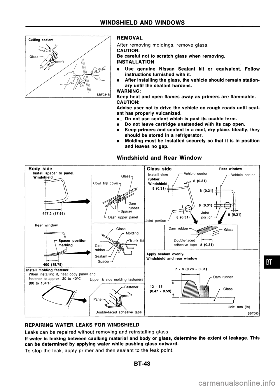
Windshield andRear Window
•
Rear
window
Vehicle center
8 (0.31)
Glass
side
Install dam
rubber.
Windshield
8(0.31)
12 -15
(0.47 -0.59)
Apply
sealant evenly.
Windshield andrear window
7 •8 (0.28 •0.31)
Unit:mm(in)
S8T083
fj
'@8(0.31)1:@
Joint8(0.31)
8 (0.31)\ portion
(J
Joint portion "
O,m ,"bb"~
G,,,,
Double-laced
adhesive tape8(0.31)
V
Fastener
P'""~
Double-laced
adhesive
tape
•
Body
side
Install spacer topanel.
Windshield
447.2 (17.61)
Rear window
t==\
h¥:~'
po"II"
markmg
•
400 (15.75)
Install molding fastener.
When installing it,heat body panel and
fastener toapprox. 30to40°C Upper
&
side molding lasteners
(86 to104°F).
0;-.
REPAIRING WATERLEAKSFORWINDSHIELD
Leaks canberepaired withoutremoving andreinstalling glass.
If water isleaking between caulking materialandbody orglass, determine theextent ofleakage. This
can bedetermined byapplying waterwhilepushing glassoutward.
To stop theleak, apply primer andthen sealant tothe leak point.
81-43
Page 266 of 1701
DoorMirror
MIRROR
CAUTION:
Be careful nottoscratch doorrearview mirrorbody.
* For Wiring Diagram, referto"POWER DOORMIRROR" inEL section.
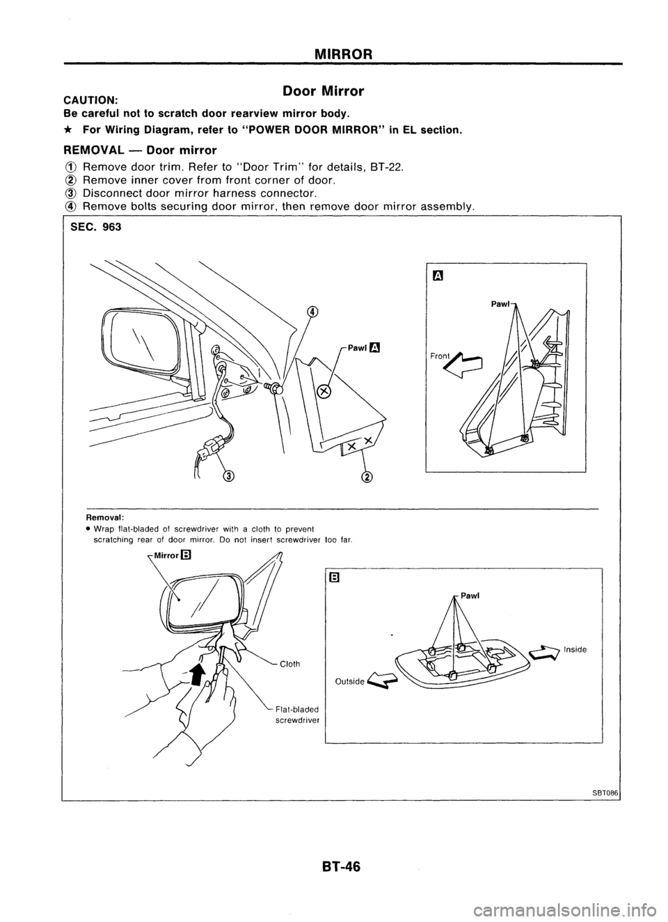
REMOVAL -Door mirror
CD
Remove doortrim. Refer to"Door Trim"fordetails, BT-22.
~ Remove innercover fromfront corner ofdoor.
~ Disconnect doormirror harness connector.
@
Remove boltssecuring doormirror, thenremove doormirror assembly.
SEC. 963
Removal:
• Wrap flat-bladed ofscrewdriver withacloth toprevent
scratching rearofdoor mirror. Donot insert screwdriver toofar.
Cloth
Flat-bladed
screwdriver
8T-46 Pawl
58T086
Page 278 of 1701
BRAKEHYDRAULIC LINE
SBR419C
For tightening flarenut
~GG94310000
or
commercial equivalent
SBR820BA
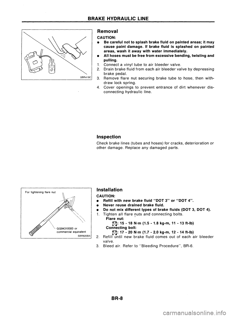
Removal
CAUTION: • Becareful nottosplash brakefluidonpainted areas;itmay
cause paintdamage. Ifbrake fluidissplashed onpainted
areas, washitaway withwater immediately.
• Allhoses mustbefree from excessive bending,tWistingand
pulling.
1 ~ Connect a
vinyl
tubetoair bleeder
valve~
2. Drain brake fluidfrom each airbleeder
valve
bydepressing
brake pedal.
3. Remove
flarenutsecuring braketubetohose, thenwith-
draw lockspring.
4. Cover
openings to
prevent
entrance ofdirt
whenever
dis-
connecting hydraulicline.
Inspection
Check brakelines(tubes andhoses) forcracks, deterioration or
other damage. Replaceanydamaged parts.
Installation
CAUTION:
• Refill withnewbrake fluid"DOT 3"or"DOT 4".
• Never reusedrained brakefluid.
• Donot mix different typesofbrake fluids(DOT3,DOT 4).
1. Tighten allflare nutsandconnecting bolts.
Flare nut: .
~: 15-18 N'm (1.5-1.8 kg-m, 11-13 ft-Ib)
Connecting bolt:
~: 17-20 N'm (1.7-2.0 kg-m, 12-14 ft-Ib)
2. Refill untilnewbrake fluidcomes outofeach airbleeder
valve.
3. Bleed air.Refer to"Bleeding Procedure", BR-6.
BR-8
Page 284 of 1701
SBR435BMASTER
CYLINDER
Assembly (Cont'd)
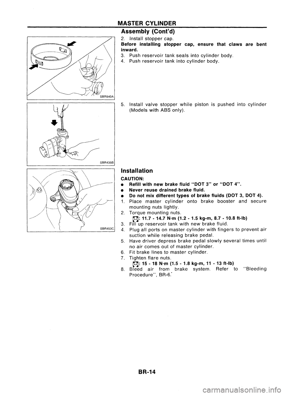
2. Install stopper cap.
Before installing stoppercap,ensure thatclaws arebent
inward.
3. Push reservoir tankseals intocylinder body.
4. Push reservoir tankintocylinder body.
5. Install valvestopper whilepiston ispushed intocylinder
(Models withABS only).
Installation
CAUTION:
• Refill withnewbrake fluid"DOT 3"or"DOT 4".
• Never reusedrained brakefluid.
• Donot mix different typesofbrake fluids(DOT3,DOT 4).
1. Place master cylinder ontobrake booster andsecure
mounting nutslightly.
2. Torque mounting nuts.
~: 11.7 -14.7 N'm(1.2-1.5 kg-m, 8.7-10.8 ft-Ib)
3. Fillupreservoir tankwith newbrake fluid.
4. Plug allports onmaster cylinder withfingers toprevent air
suction whilereleasing brakepedal.
5. Have driver depress brakepedalslowly several timesuntil
no air comes outofmaster cylinder.
6. Fitbrake linestomaster cylinder.
7. Tighten flarenuts.
~: 15-18 N'm (1.5-1.8 kg-m, 11-13 ft-Ib)
8. Bleed airfrom brake system. Referto"Bleeding
Procedure", BR-6."
BR-14
Page 286 of 1701
Approx.125mm (4.92 In) BRAKE
BOOSTER
Inspection
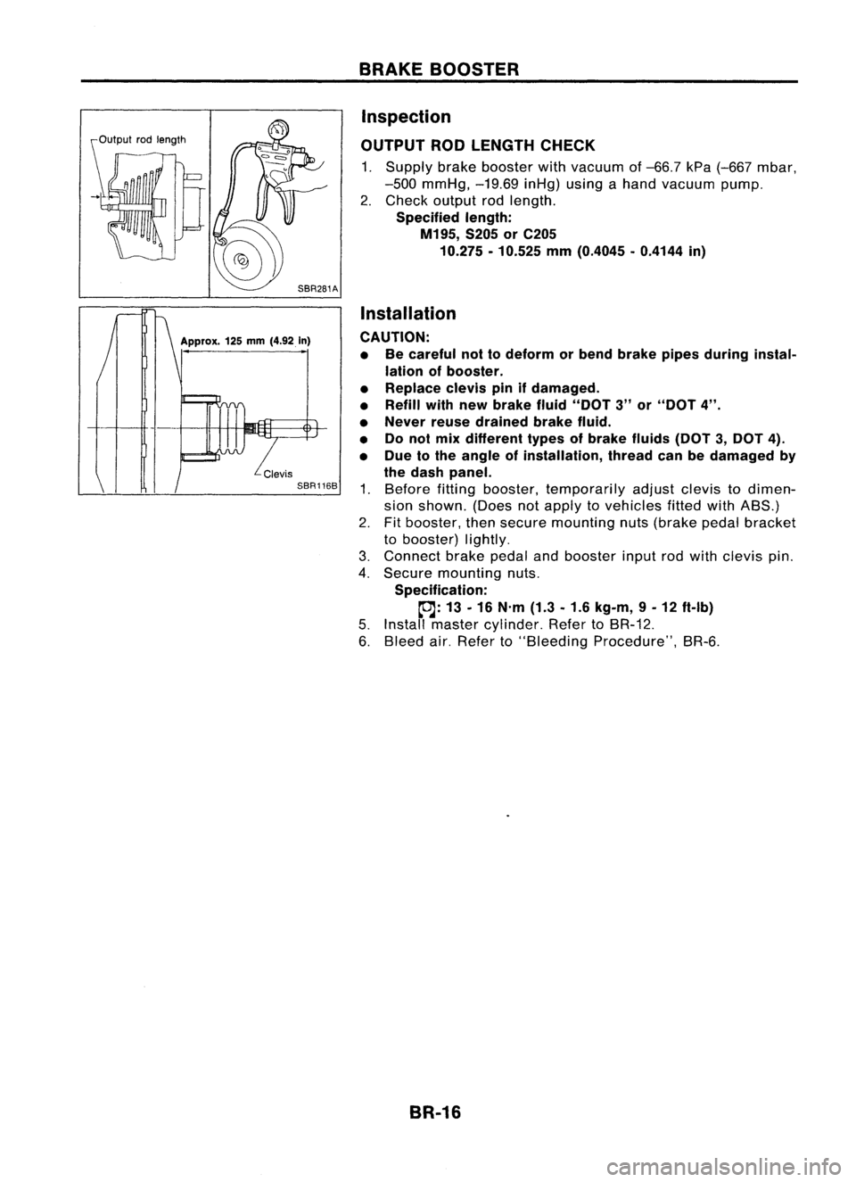
OUTPUT RODLENGTH CHECK
1. Supply brakebooster withvacuum of-66.7 kPa(-667 mbar,
-500 mmHg, -19.69inHg)usingahand vacuum pump.
2. Check output rodlength.
Specified length:
M195, S205orC205
10.275 -10.525 mm(0.4045 -0.4144 in)
Installation
CAUTION: • Becareful nottodeform orbend brake pipesduring instal-
lation ofbooster.
• Replace clevispinifdamaged.
• Refill withnewbrake fluid"DOT 3"or"DOT 4".
• Never reusedrained brakefluid.
• Donol mix different typesofbrake fluids(DOT3,DOT 4).
• Due tothe angle ofinstallation, threadcanbedamaged by
the dash panel.
1. Before fittingbooster, temporarily adjustclevistodimen-
sion shown. (Doesnotapply tovehicles fittedwithABS.)
2. Fitbooster, thensecure mounting nuts(brake pedalbracket
to booster) lightly.
3. Connect brakepedalandbooster inputrodwith clevis pin.
4. Secure mounting nuts.
Specification:
~: 13-16 N'm (1.3-1.6 kg-m, 9-12 ft-Ib)
5. Install master cylinder. RefertoBR-12.
6. Bleed air.Refer to"Bleeding Procedure", BR-6.
BR-16
Page 293 of 1701
Pistonbootretainer (AD22VF only)
Piston boot
Piston seal
FRONT
DISCBRAKE
Inspection -Caliper (Cont'd)
PISTON
Check pistonforscore, rust,wear, damage orpresence offor-
eign objects. Replace ifany ofthe above conditions are
observed.
CAUTION:
Piston sliding surface isplated. Donot polish withemery paper
even ifrust orforeign objects arestuck tosliding surface.
SLIDE PIN,PINBOLT ANDPINBOOT
Check forwear, cracks, rustorother damage. Replaceifany of
the above conditions areobserved.
Inspection -Rotor
RUNOUT
1: Secure rotortowheel hubwith atleast twonuts (M12 x
1.25).
2. Check runout usingadial indicator.
Make surethatwheel bearing axialendplay iswithin thespec-
ifications beforemeasuring. RefertoFA section ("FrontWheel
Bearing", "ON-VEHICLE SERVICE").
Maximum runout:
SBR936A 0.07mm(0.0028 in)
3.
If
the runout isout ofspecification, findminimum runout
position asfollows:
a. Remove nutsandrotor fromwheel hub.
b. Shift therotor onehole andsecure rotortowheel hub
with nuts.
c. Measure runout.
d. Repeat stepsa.to c.so that minimum runoutposition can
be found.
4. Ifthe runout isstill outofspecification, turnrotor withon-car
brake lathe("MAD, DL-8700", "AMMCO700and 705" or•••
equivalent).
THICKNESS Thickness variation(Atleast 8positions):
Maximum 0.02mm(0.0008 in)
If thickness variationexceedsthespecification, turnrotor with
on-car brakelathe.
Rotor repair limit:
CL22VD andCL22VE 16.0mm(0.630 in)
CL22VF 24.0mm(0.945 in)
SBR944A Assembly
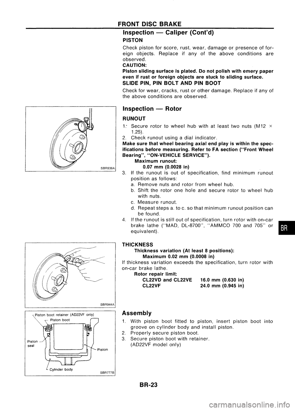
1. With piston bootfitted topiston, insertpiston bootinto
groove oncylinder bodyandinstall piston.
2. Properly securepistonboot.
3. Secure pistonbootwithretainer.
(AD22VF modelonly)
Piston
SBR777B BR-23