1995 ACURA TL battery
[x] Cancel search: batteryPage 888 of 1771
Idle Contro l Syste m
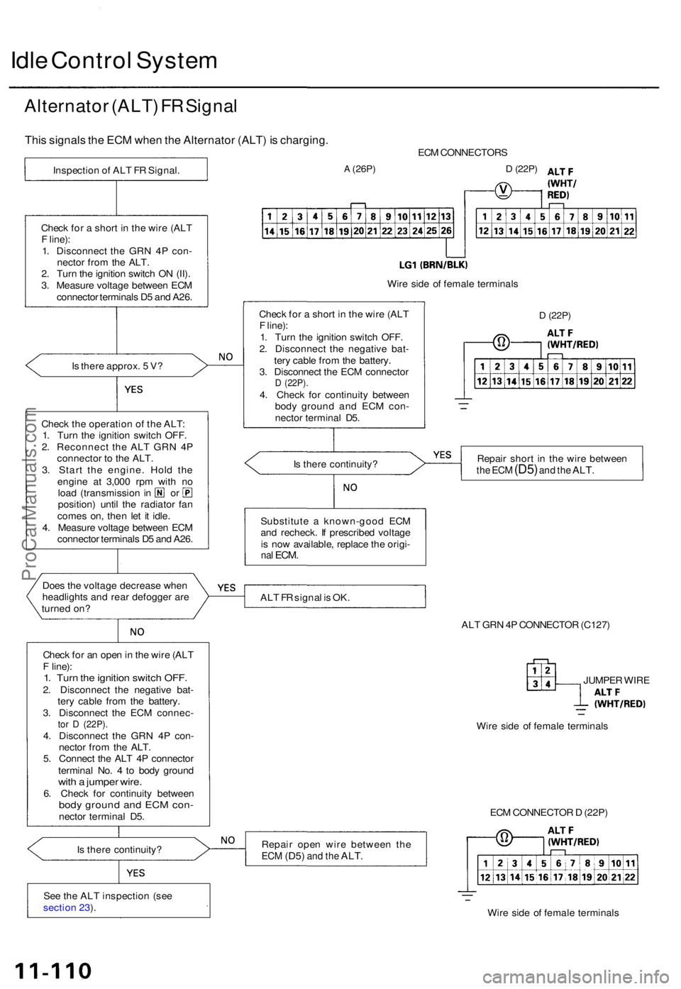
Alternato r (ALT ) F R Signa l
This signal s th e EC M whe n th e Alternato r (ALT ) i s charging .
Is ther e approx . 5 V ?
Chec k th e operatio n o f th e ALT :
1 . Tur n th e ignitio n switc h OFF .
2 . Reconnec t th e AL T GR N 4 P
connecto r t o th e ALT .
3 . Star t th e engine . Hol d th e
engin e a t 3,00 0 rp m wit h n o
loa d (transmissio n in o r
position ) unti l th e radiato r fa n
come s on , the n le t i t idle .
4 . Measur e voltag e betwee n EC M
connecto r terminal s D 5 an d A26 .
Doe s th e voltag e decreas e whe n
headlight s an d rea r defogge r ar e
turne d on ?
Chec k fo r a n ope n in th e wir e (AL T
F line) :
1. Tur n th e ignitio n switc h OFF .2. Disconnec t th e negativ e bat -
ter y cabl e fro m th e battery .
3 . Disconnec t th e EC M connec -
tor D (22P) .4. Disconnec t th e GR N 4 P con -
necto r fro m th e ALT .
5 . Connec t th e AL T 4 P connecto r
termina l No . 4 to bod y groun d
with a jumpe r wire .6. Chec k fo r continuit y betwee nbody groun d an d EC M con -necto r termina l D5 .
I s ther e continuity ?
Se e th e AL T inspectio n (se e
sectio n 23 ). EC
M CONNECTOR S
A (26P)D (22P)
Wire sid e o f femal e terminal s
D (22P)
Repai r shor t i n th e wir e betwee nthe EC M (D5 ) and th e ALT .
ALT F R signa l i s OK .
ALT GR N 4P CONNECTO R (C127 )
JUMPE R WIR E
Wir e sid e o f femal e terminal s
Repai r ope n wir e betwee n th e
ECM (D5 ) and th e ALT .
ECM CONNECTO R D (22P )
Wir e sid e o f femal e terminal s
Substitut
e a known-goo d EC M
an d recheck . I f prescribe d voltag e
i s no w available , replac e th e origi -
nal ECM .
Is ther e continuity ?
Chec
k fo r a shor t i n th e wir e (AL T
F line) :
1 . Tur n th e ignitio n switc h OFF .
2 . Disconnec t th e negativ e bat -
ter y cabl e fro m th e battery .
3 . Disconnec t th e EC M connecto r
D (22P) .4. Chec k fo r continuit y betwee n
bod y groun d an d EC M con -
necto r termina l D5 .
Chec
k fo r a shor t i n th e wir e (AL T
F line) :
1 . Disconnec t th e GR N 4 P con -
necto r fro m th e ALT .
2 . Tur n th e ignitio n switc h O N (II) .
3 . Measur e voltag e betwee n EC M
connecto r terminal s D 5 an d A26 .
Inspectio
n o f AL T F R Signal .
ProCarManuals.com
Page 901 of 1771
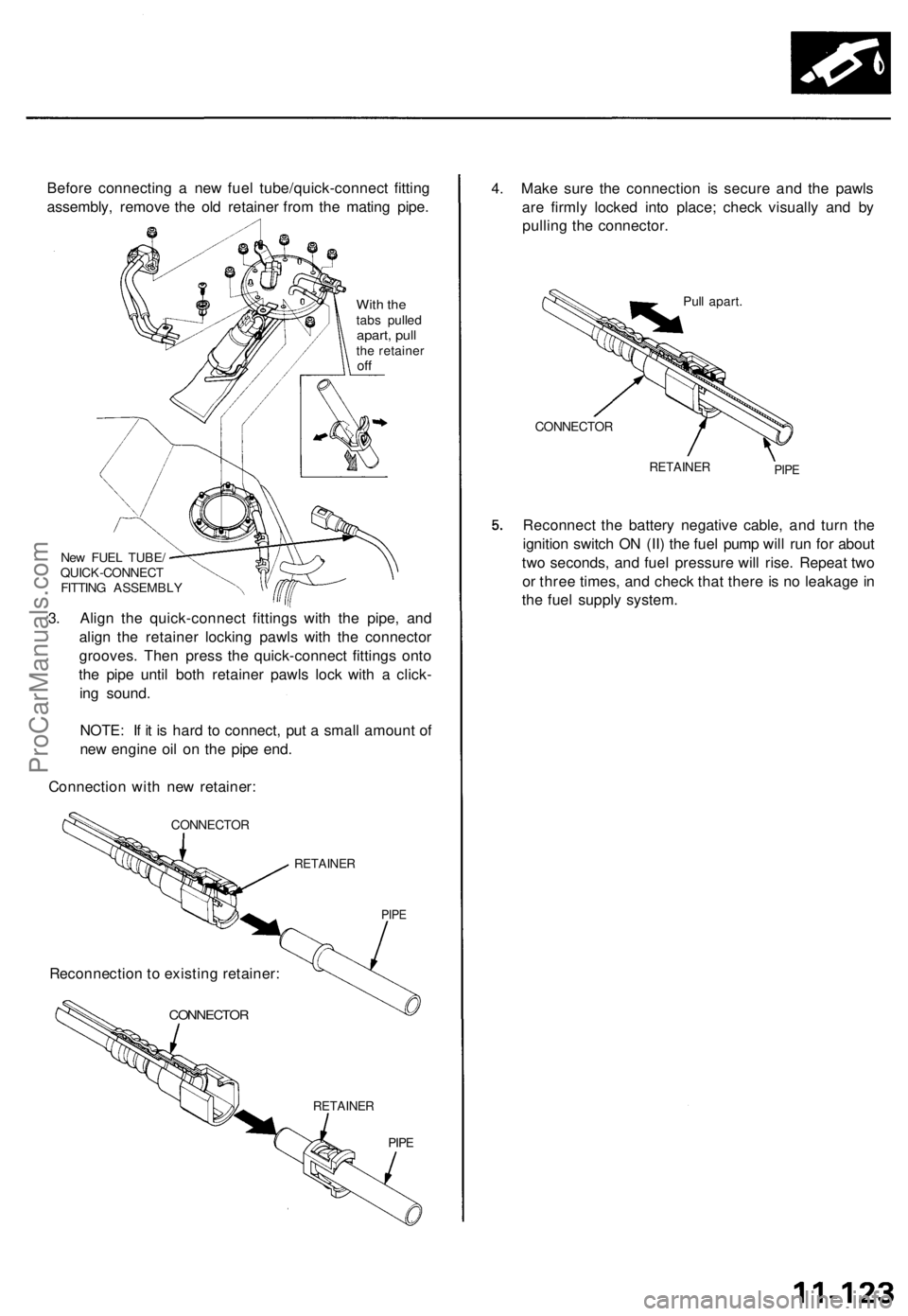
Before connecting a new fuel tube/quick-connect fitting
assembly, remove the old retainer from the mating pipe.
With the
tabs pulled
apart, pull
the retainer
off
New FUEL TUBE/
QUICK-CONNECT
FITTING ASSEMBLY
3. Align the quick-connect fittings with the pipe, and
align the retainer locking pawls with the connector
grooves. Then press the quick-connect fittings onto
the pipe until both retainer pawls lock with a click-
ing sound.
NOTE: If it is hard to connect, put a small amount of
new engine oil on the pipe end.
Connection with new retainer:
CONNECTOR
RETAINER
PIPE
CONNECTOR
RETAINER
PIPE
4. Make sure the connection is secure and the pawls
are firmly locked into place; check visually and by
pulling the connector.
Pull apart.
CONNECTOR
RETAINER
PIPE
Reconnect the battery negative cable, and turn the
ignition switch ON (II) the fuel pump will run for about
two seconds, and fuel pressure will rise. Repeat two
or three times, and check that there is no leakage in
the fuel supply system.
Reconnection to existing retainer:ProCarManuals.com
Page 903 of 1771
Fuel Supply System
Fuel Pressure
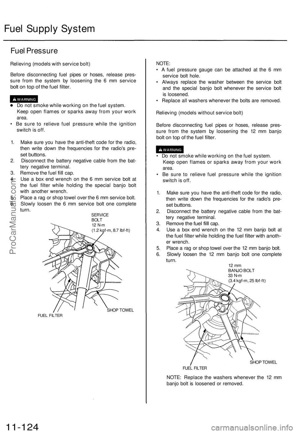
Relieving (models with service bolt)
Before disconnecting fuel pipes or hoses, release pres-
sure from the system by loosening the 6 mm service
bolt on top of the fuel filter.
Do not smoke while working on the fuel system.
Keep open flames or sparks away from your work
area.
• Be sure to relieve fuel pressure while the ignition
switch is off.
1. Make sure you have the anti-theft code for the radio,
then write down the frequencies for the radio's pre-
set buttons.
2. Disconnect the battery negative cable from the bat-
tery negative terminal.
3.
Remove
the
fuel
fill
cap.
4. Use a box end wrench on the 6 mm service bolt at
the fuel filter while holding the special banjo bolt
with another wrench.
5. Place a rag or shop towel over the 6 mm service bolt.
6. Slowly loosen the 6 mm service bolt one complete
turn.
SERVICE
BOLT
12 N-m
(1.2 kgf-m, 8.7 Ibf-ft)
SHOP TOWEL
FUEL FILTER
NOTE:
• A fuel pressure gauge can be attached at the 6 mm
service bolt hole.
• Always replace the washer between the service bolt
and the special banjo bolt whenever the service bolt
is loosened.
• Replace all washers whenever the bolts are removed.
Relieving (models without service bolt)
Before disconnecting fuel pipes or hoses, release pres-
sure from the system by loosening the 12 mm banjo
bolt on top of the fuel filter.
• Do not smoke while working on the fuel system.
Keep open flames or sparks away from your work
area.
• Be sure to relieve fuel pressure while the ignition
switch is off.
1. Make sure you have the anti-theft code for the radio,
then write down the frequencies for the radio's pre-
set buttons.
2. Disconnect the battery negative cable from the bat-
tery negative terminal.
3.
Remove
the
fuel
fill
cap.
4. Use a box end wrench on the 12 mm banjo bolt at
the fuel filter while holding the fuel filter with anoth-
er wrench.
5. Place a rag or shop towel over the 12 mm banjo bolt.
6. Slowly loosen the 12 mm banjo bolt one complete
turn.
12 mm
BANJO BOLT
33 N-m
(3.4 kgf-m, 25 Ibf-ft)
SHOP TOWEL
FUEL FILTER
NOTE: Replace the washers whenever the 12 mm
banjo bolt is loosened or removed.
11-124ProCarManuals.com
Page 914 of 1771
PGM-FI Main Relay
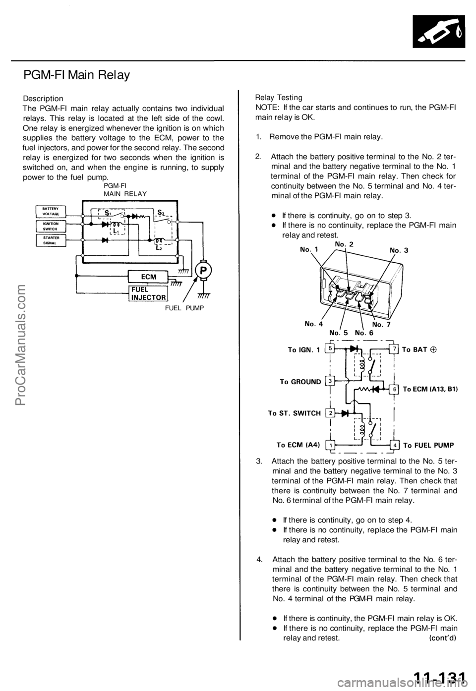
Description
The PGM-FI main relay actually contains two individual
relays. This relay is located at the left side of the cowl.
One relay is energized whenever the ignition is on which
supplies the battery voltage to the ECM, power to the
fuel injectors, and power for the second relay. The second
relay is energized for two seconds when the ignition is
switched on, and when the engine is running, to supply
power to the fuel pump.
PGM-FI
MAIN RELAY
FUEL PUMP
Relay Testing
NOTE: If the car starts and continues to run, the PGM-FI
main relay is OK.
1. Remove the PGM-FI main relay.
2.
Attach the battery positive terminal to the No. 2 ter-
minal and the battery negative terminal to the No. 1
terminal of the PGM-FI main relay. Then check for
continuity between the No. 5 terminal and No. 4 ter-
minal of the PGM-FI main relay.
If there is continuity, go on to step 3.
If there is no continuity, replace the PGM-FI main
relay and retest.
3. Attach the battery positive terminal to the No. 5 ter-
minal and the battery negative terminal to the No. 3
terminal of the PGM-FI main relay. Then check that
there is continuity between the No. 7 terminal and
No. 6 terminal of the PGM-FI main relay.
If there is continuity, go on to step 4.
If there is no continuity, replace the PGM-FI main
relay and retest.
4. Attach the battery positive terminal to the No. 6 ter-
minal and the battery negative terminal to the No. 1
terminal of the PGM-FI main relay. Then check that
there is continuity between the No. 5 terminal and
No. 4 terminal of the PGM-FI main relay.
If there is continuity, the PGM-FI main relay is OK.
If there is no continuity, replace the PGM-FI main
relay and retest.ProCarManuals.com
Page 1007 of 1771
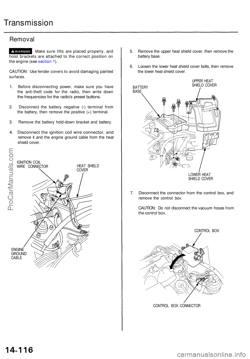
Transmission
Removal
Make sur e lift s ar e place d properly , an d
hois t bracket s ar e attache d t o th e correc t positio n o n
th e engin e (se e sectio n 1 ).
CAUTION : Us e fende r cover s t o avoi d damagin g painte d
surfaces .
1. Befor e disconnectin g power , mak e sur e yo u hav e
th e anti-thef t cod e fo r th e radio , the n writ e dow n
the frequencie s fo r th e radio' s prese t buttons .
2. Disconnec t th e batter y negativ e (- ) termina l fro m
th e battery , the n remov e th e positiv e (+ ) terminal .
3 . Remov e th e batter y hold-dow n bracke t an d battery .
4. Disconnec t th e ignitio n coi l wir e connector , an d
remov e i t an d th e engin e groun d cabl e fro m th e hea t
shiel d cover .
IGNITIO N COI LWIRE CONNECTO R HEA
T SHIEL D
COVE R
ENGIN EGROUN DCABLE
5. Remov e th e uppe r hea t shiel d cover , the n remov e th e
batter y base .
6 . Loose n th e lowe r hea t shiel d cove r bolts , the n remov e
th e lowe r hea t shiel d cover .
BATTER YBASE
UPPE R HEA T
SHIEL D COVE R
LOWE R HEA T
SHIEL D COVE R
7. Disconnec t th e connecto r fro m th e contro l box , an d
remov e th e contro l box .
CAUTION : D o no t disconnec t th e vacuu m hose s fro m
th e contro l box .
CONTRO L BO X
CONTRO L BO X CONNECTO R
ProCarManuals.com
Page 1038 of 1771
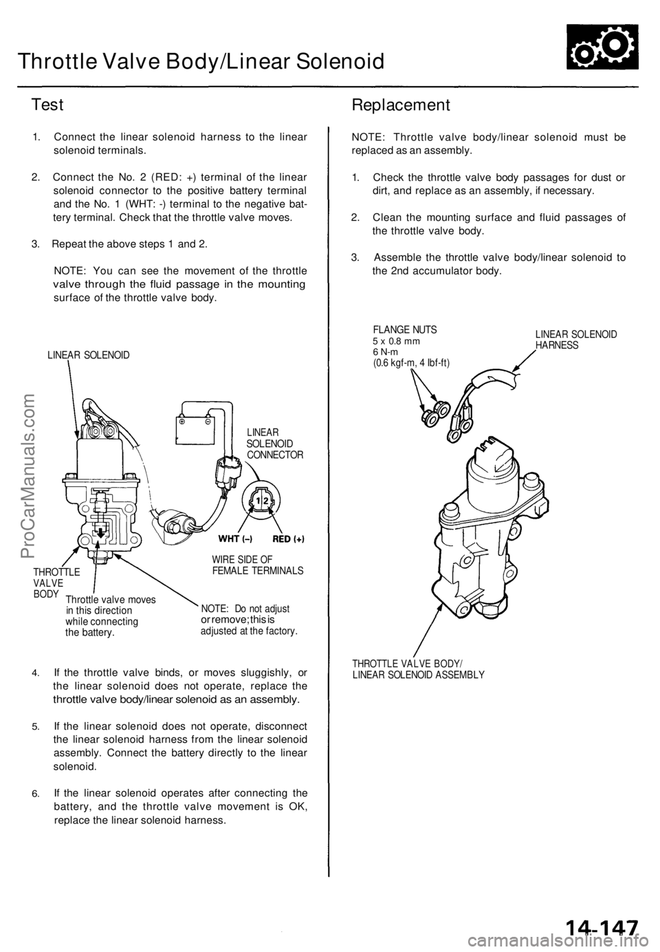
Throttle Valv e Body/Linea r Solenoi d
Test
1. Connec t th e linea r solenoi d harnes s t o th e linea r
solenoi d terminals .
2 . Connec t th e No . 2 (RED : + ) termina l o f th e linea r
solenoi d connecto r t o th e positiv e batter y termina l
an d th e No . 1 (WHT : - ) termina l t o th e negativ e bat -
ter y terminal . Chec k tha t th e throttl e valv e moves .
3 . Repea t th e abov e step s 1 an d 2 .
NOTE : Yo u ca n se e th e movemen t o f th e throttl e
valve throug h th e flui d passag e i n th e mountin g
surface o f th e throttl e valv e body .
LINEA R SOLENOI D
Replacemen t
LINEARSOLENOI DCONNECTO R
THROTTLEVALVEBODYThrottl e valv e move sin thi s directio nwhile connectin gthe battery .
WIRE SID E O FFEMAL E TERMINAL S
NOTE: D o no t adjus tor remove ; thi s isadjuste d a t th e factory .
4.
5 .
6.
If th e throttl e valv e binds , o r move s sluggishly , o r
th e linea r solenoi d doe s no t operate , replac e th e
throttl e valv e body/linea r solenoi d a s a n assembly .
If th e linea r solenoi d doe s no t operate , disconnec t
th e linea r solenoi d harnes s fro m th e linea r solenoi d
assembly . Connec t th e batter y directl y t o th e linea r
solenoid .
I f th e linea r solenoi d operate s afte r connectin g th e
battery , an d th e throttl e valv e movemen t i s OK ,
replac e th e linea r solenoi d harness . NOTE
: Throttl e valv e body/linea r solenoi d mus t b e
replace d a s a n assembly .
1 . Chec k th e throttl e valv e bod y passage s fo r dus t o r
dirt , an d replac e a s a n assembly , i f necessary .
2 . Clea n th e mountin g surfac e an d flui d passage s o f
th e throttl e valv e body .
3 . Assembl e th e throttl e valv e body/linea r solenoi d t o
th e 2n d accumulato r body .
FLANG E NUT S5 x 0. 8 m m6 N- m(0.6 kgf-m , 4 Ibf-ft )
LINEA R SOLENOI DHARNESS
THROTTL E VALV E BODY /LINEAR SOLENOI D ASSEMBL Y
ProCarManuals.com
Page 1083 of 1771
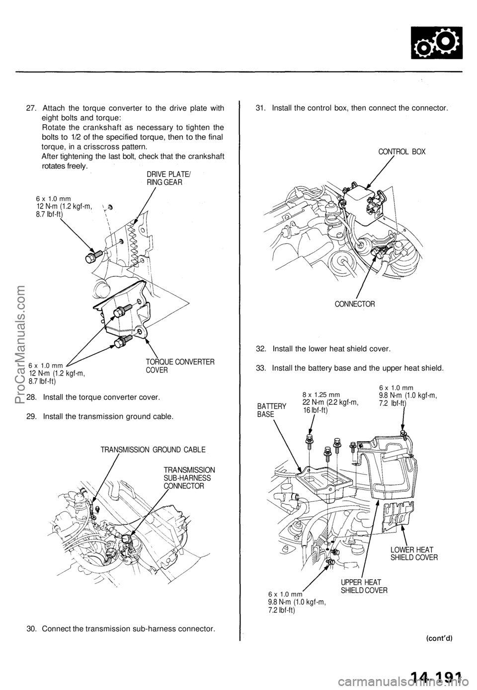
27. Attach the torque converter to the drive plate with
eight bolts and torque:
Rotate the crankshaft as necessary to tighten the
bolts to 1/2 of the specified torque, then to the final
torque, in a crisscross pattern.
After tightening the last bolt, check that the crankshaft
rotates freely.
DRIVE PLATE/
RING GEAR
6 x 1.0 mm
12 N-m (1.2 kgf-m,
8.7 Ibf-ft)
6 x 1.0 mm
12 N-m (1.2 kgf-m,
8.7 Ibf-ft)
TORQUE CONVERTER
COVER
28. Install the torque converter cover.
29. Install the transmission ground cable.
TRANSMISSION GROUND CABLE
TRANSMISSION
SUB-HARNESS
CONNECTOR
30. Connect the transmission sub-harness connector.
31. Install the control box, then connect the connector.
CONTROL BOX
CONNECTOR
32. Install the lower heat shield cover.
33. Install the battery base and the upper heat shield.
6 x 1.0 mm
9.8 N-m (1.0 kgf-m,
7.2 Ibf-ft)
LOWER HEAT
SHIELD COVER
6 x 1.0 mm
9.8 N-m (1.0 kgf-m,
7.2 Ibf-ft)
UPPER HEAT
SHIELD COVER
8 x
1.25
mm
22 N-m (2.2 kgf-m,
16 Ibf-ft)
BATTERY
BASEProCarManuals.com
Page 1096 of 1771
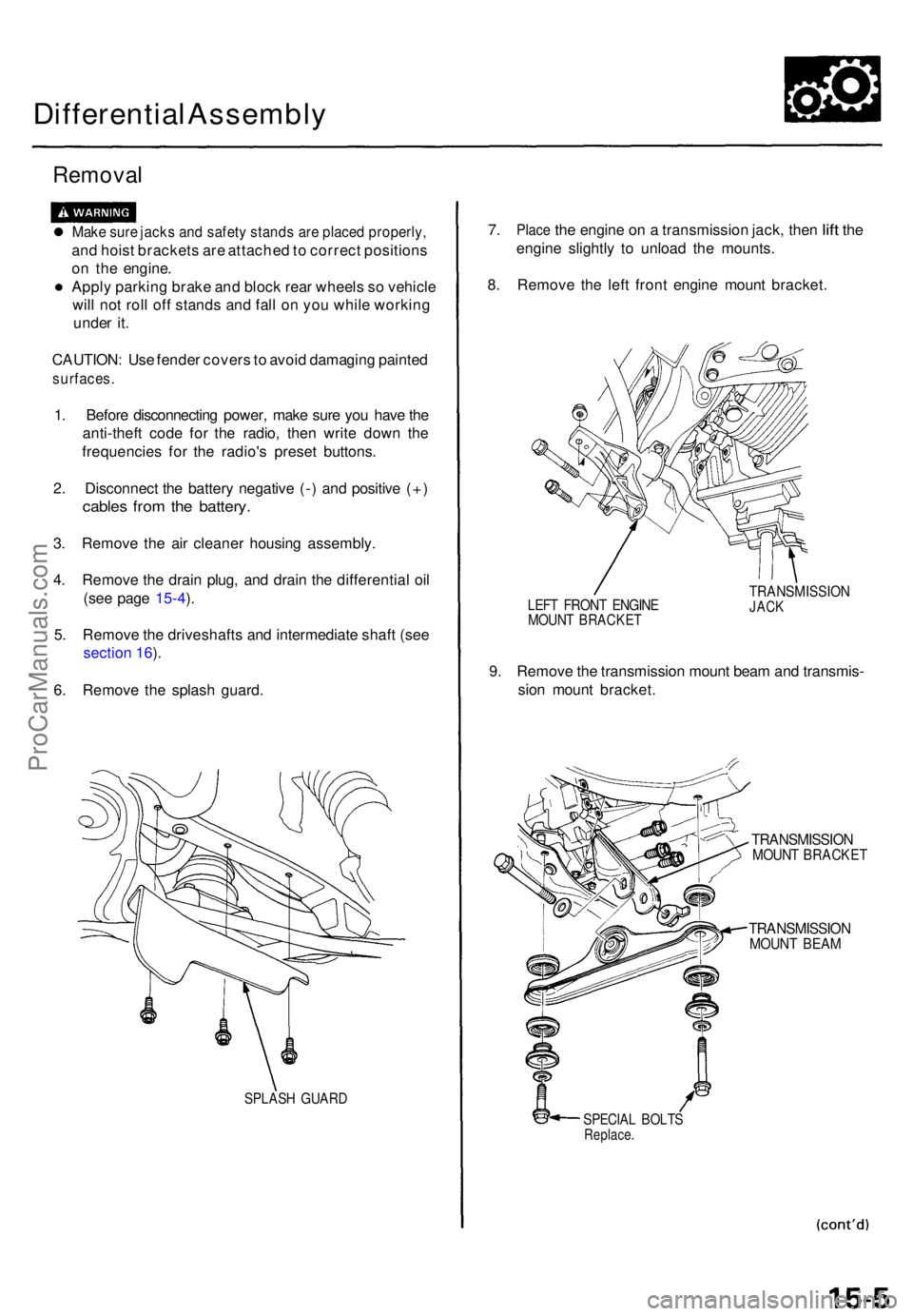
Differential Assembl y
Removal
Make sur e jack s an d safet y stand s ar e place d properly ,
and hois t bracket s ar e attache d to correc t position s
o n th e engine .
• Apply parkin g brak e an d bloc k rea r wheel s s o vehicl e
wil l no t rol l of f stand s an d fal l o n yo u whil e workin g
unde r it .
CAUTION : Us e fende r cover s to avoi d damagin g painte d
surfaces .
1. Befor e disconnectin g power , mak e sur e yo u hav e th e
anti-thef t cod e fo r th e radio , the n writ e dow n th e
frequencie s fo r th e radio' s prese t buttons .
2 . Disconnec t th e batter y negativ e (- ) an d positiv e (+ )
cable s fro m th e battery .
3. Remov e th e ai r cleane r housin g assembly .
4 . Remov e th e drai n plug , an d drai n th e differentia l oi l
(se e pag e 1 5-4 ).
5 . Remov e th e driveshaft s an d intermediat e shaf t (se e
sectio n 16 ).
6 . Remov e th e splas h guard .
SPLAS H GUAR D
7. Plac e the engin e on a transmissio n jack , the n lift th e
engin e slightl y t o unloa d th e mounts .
8 . Remov e th e lef t fron t engin e moun t bracket .
LEFT FRON T ENGIN EMOUNT BRACKE T
TRANSMISSIO NJACK
9. Remov e th e transmissio n moun t bea m an d transmis -
sio n moun t bracket .
TRANSMISSIO NMOUNT BRACKE T
TRANSMISSIO NMOUNT BEA M
SPECIA L BOLT SReplace .
ProCarManuals.com