1995 ACURA TL battery
[x] Cancel search: batteryPage 1497 of 1771
Troubleshooting
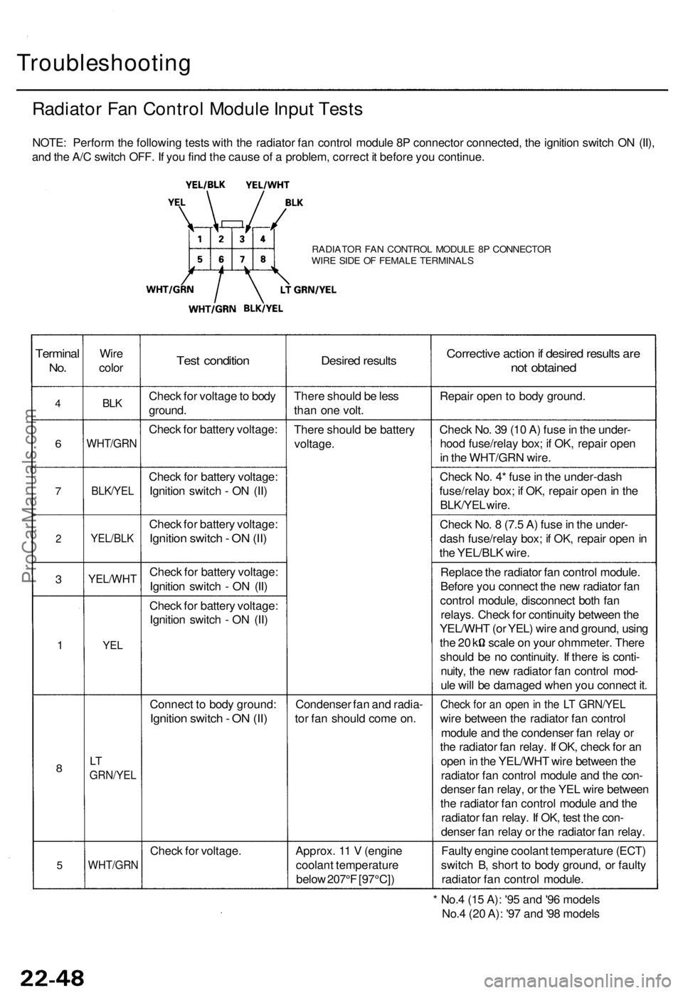
Radiator Fan Control Module Input Tests
NOTE: Perform the following tests with the radiator fan control module 8P connector connected, the ignition switch ON (II),
and the A/C switch OFF. If you find the cause of a problem, correct it before you continue.
RADIATOR FAN CONTROL MODULE 8P CONNECTOR
WIRE SIDE OF FEMALE TERMINALS
Terminal
No.
4
6
7
2
3
1
8
5
Wire
color
BLK
WHT/GRN
BLK/YEL
YEL/BLK
YEL/WHT
YEL
LT
GRN/YEL
WHT/GRN
Test condition
Check for voltage to body
ground.
Check for battery voltage:
Check for battery voltage:
Ignition switch - ON (II)
Check for battery voltage:
Ignition switch - ON (II)
Check for battery voltage:
Ignition switch - ON (II)
Check for battery voltage:
Ignition switch - ON (II)
Connect to body ground:
Ignition switch - ON (II)
Check for voltage.
Desired results
There should be less
than one volt.
There should be battery
voltage.
Condenser fan and radia-
tor fan should come on.
Approx. 11 V (engine
coolant temperature
below 207°F [97°C])
Corrective action if desired results are
not obtained
Repair open to body ground.
Check No. 39 (10 A) fuse in the under-
hood fuse/relay box; if OK, repair open
in the WHT/GRN wire.
Check No. 4* fuse in the under-dash
fuse/relay box; if OK, repair open in the
BLK/YEL wire.
Check No. 8 (7.5 A) fuse in the under-
dash fuse/relay box; if OK, repair open in
the YEL/BLK wire.
Replace the radiator fan control module.
Before you connect the new radiator fan
control module, disconnect both fan
relays. Check for continuity between the
YEL/WHT (or YEL) wire and ground, using
the 20 k scale on your ohmmeter. There
should be no continuity. If there is conti-
nuity, the new radiator fan control mod-
ule will be damaged when you connect it.
Check for an open in the LT GRN/YEL
wire between the radiator fan control
module and the condenser fan relay or
the radiator fan relay. If OK, check for an
open in the YEL/WHT wire between the
radiator fan control module and the con-
denser fan relay, or the YEL wire between
the radiator fan control module and the
radiator fan relay. If OK, test the con-
denser fan relay or the radiator fan relay.
Faulty engine coolant temperature (ECT)
switch B, short to body ground, or faulty
radiator fan control module.
* No.4 (15 A): '95 and '96 models
No.4 (20 A): '97 and '98 modelsProCarManuals.com
Page 1507 of 1771
Heater Valve
Test
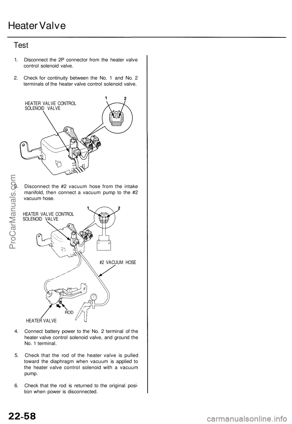
1. Disconnect the 2P connector from the heater valve
control solenoid valve.
2. Check for continuity between the No. 1 and No. 2
terminals of the heater valve control solenoid valve.
HEATER VALVE CONTROL
SOLENOID VALVE
3. Disconnect the #2 vacuum hose from the intake
manifold, then connect a vacuum pump to the #2
vacuum hose.
HEATER VALVE CONTROL
SOLENOID VALVE
#2 VACUUM HOSE
HEATER VALVE
4. Connect battery power to the No. 2 terminal of the
heater valve control solenoid valve, and ground the
No. 1 terminal.
5. Check that the rod of the heater valve is pulled
toward the diaphragm when vacuum is applied to
the heater valve control solenoid with a vacuum
pump.
6. Check that the rod is returned to the original posi-
tion when power is disconnected.
RODProCarManuals.com
Page 1513 of 1771
Heater Uni t
Replacemen t
SRS component s ar e locate d i n thi s area . Revie w th e
SR S componen t locations , precautions , an d procedure s
i n th e SR S ( sectio n 24 ) befor e performin g repair s o r ser -
vice .
1 . Disconnec t th e negativ e cabl e fro m th e battery .
2 . Whe n th e engin e i s cool , drai n th e engin e coolan t
fro m th e radiato r (se e sectio n 10 ).
D o no t remov e th e radiato r ca p whe n
th e engin e i s hot ; th e engin e coolan t i s unde r pres -
sur e an d coul d severel y scal d you .
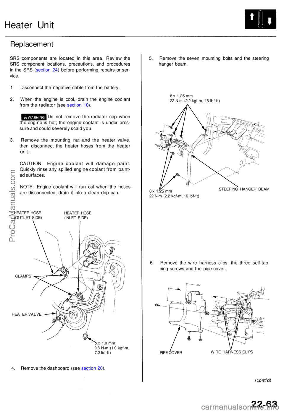
3 . Remov e th e mountin g nu t an d th e heate r valve ,
the n disconnec t th e heate r hose s fro m th e heate r
unit.
CAUTION : Engin e coolan t wil l damag e paint .
Quickl y rins e an y spille d engin e coolan t fro m paint -
e d surfaces .
NOTE : Engin e coolan t wil l ru n ou t whe n th e hose s
ar e disconnected ; drai n i t int o a clea n dri p pan .
HEATE R HOS E
(OUTLE T SIDE ) HEATE
R HOS E
(INLE T SIDE )
CLAMP S
HEATE R VALV E
6 x 1. 0 m m9.8 N- m (1. 0 kgf-m ,
7. 2 Ibf-ft )
4. Remov e th e dashboar d (se e sectio n 20 ). 5
. Remov e th e seve n mountin g bolt s an d th e steerin g
hange r beam .
8 x 1.2 5 mm22 N- m (2. 2 kgf-m , 1 6 Ibf-ft )
8 x 1.2 5 mm22 N- m (2. 2 kgf-m , 1 6 Ibf-ft ) STEERIN
G HANGE R BEA M
6. Remov e th e wir e harnes s clips , th e thre e self-tap -
pin g screw s an d th e pip e cover .
PIPE COVE R WIR
E HARNES S CLIP S
ProCarManuals.com
Page 1522 of 1771
Compressor
Replacemen t
1. I f th e compresso r i s marginall y operable , ru n th e
engin e a t idl e speed , an d le t th e ai r conditione r
wor k fo r a fe w minutes , the n shu t th e engin e off .
2 . Disconnec t th e negativ e cabl e fro m th e battery .
3 . Recove r th e refrigeran t wit h a Recovery/Recycling /
Chargin g Syste m (se e pag e 22-71 ).
4 . Remov e th e intak e ai r duc t (se e sectio n 5) .
5 . Remov e th e A/ C compresso r bel t (se e pag e 22-78 ).
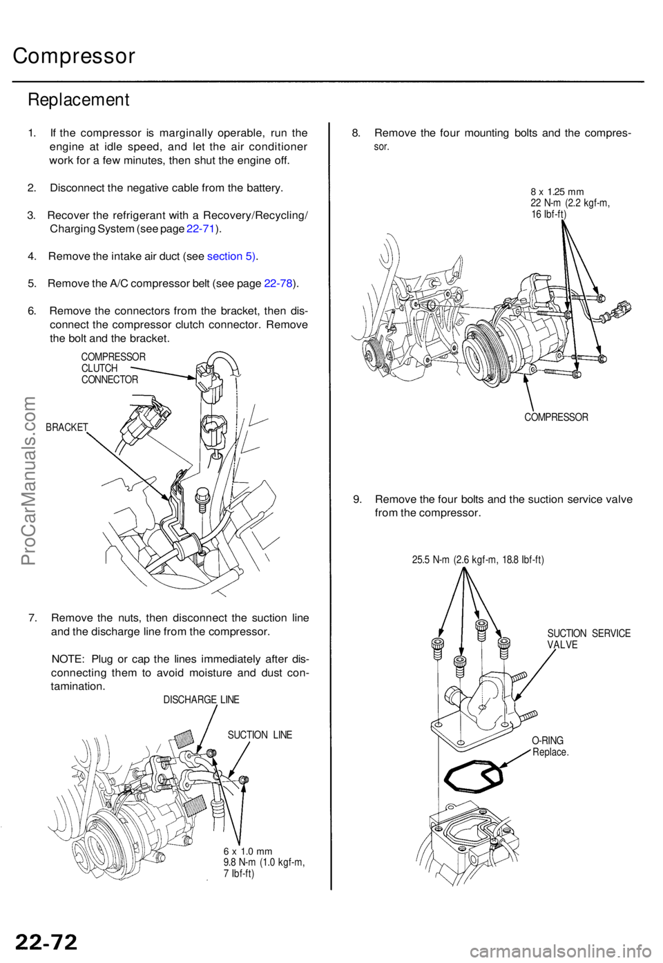
6 . Remov e th e connector s fro m th e bracket , the n dis -
connec t th e compresso r clutc h connector . Remov e
th e bol t an d th e bracket .
COMPRESSO R
CLUTC H
CONNECTO R
BRACKET
7. Remov e th e nuts , the n disconnec t th e suctio n lin e
an d th e discharg e lin e fro m th e compressor .
NOTE : Plu g o r ca p th e line s immediatel y afte r dis -
connectin g the m to avoi d moistur e an d dus t con -
tamination .
DISCHARG E LIN E
SUCTIO N LIN E
6 x 1. 0 m m9.8 N- m (1. 0 kgf-m ,
7 Ibf-ft )
8. Remov e th e fou r mountin g bolt s an d th e compres -
sor.
8 x 1.2 5 mm22 N- m (2. 2 kgf-m ,
1 6 Ibf-ft )
COMPRESSO R
9. Remov e th e fou r bolt s an d th e suctio n servic e valv e
fro m th e compressor .
25.5 N- m (2. 6 kgf-m , 18. 8 Ibf-ft )
SUCTIO N SERVIC E
VALV E
O-RIN G
Replace .
ProCarManuals.com
Page 1536 of 1771

Troubleshooting
Tips and Precautions
Before Troubleshooting
Check applicable fuses in the appropriate fuse/relay
box.
Check the battery for damage, state of charge, and
clean and tight connections.
Check the alternator belt tension.
CAUTION:
Do not quick-charge a battery unless the battery
ground cable has been disconnected, otherwise you
will damage the alternator diodes.
Do not attempt to crank the engine with the battery
ground cable loosely connected or you will severely
damage the wiring.
Handling Connectors
Make sure the connectors are clean and have no loose
wire terminals.
Make sure multiple cavity connectors are packed with
grease (except waterproof connectors).
All connectors have push-down release type locks.
LOCKING TAB
Some connectors have a clip on their side used to
attach them to a mount bracket on the body or on
another component. This clip has a pull type lock.
Some mounted connectors cannot be disconnected
unless you first release the lock and remove the con-
nector from its mount bracket.
LOCKING
PAWL ON
OTHER
HALF OF
CONNECTOR
Pull to
disengage
BRACKET
Never try to disconnect connectors by pulling on
their wires; pull on the connector halves instead.
Always reinstall plastic covers.
Before connecting connectors, make sure the termi-
nals are in place and not bent.
BENT TERMINAL
Check for loose retainer and rubber seals.
RETAINER
RUBBER SEAL RETAINER
The backs of some connectors are packed with
grease. Add grease if necessary. If the grease is con-
taminated, replace it.
LOCKING TABProCarManuals.com
Page 1545 of 1771
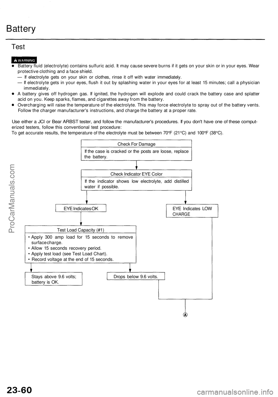
Battery
Test
Battery fluid (electrolyte) contains sulfuric acid. It may cause severe burns if it gets on your skin or in your eyes. Wear
protective clothing and a face shield.
— If electrolyte gets on your skin or clothes, rinse it off with water immediately.
— If electrolyte gets in your eyes, flush it out by splashing water in your eyes for at least 15 minutes; call a physician
immediately.
A battery gives off hydrogen gas. If ignited, the hydrogen will explode and could crack the battery case and splatter
acid on you. Keep sparks, flames, and cigarettes away from the battery.
Overcharging will raise the temperature of the electrolyte. This may force electrolyte to spray out of the battery vents.
Follow the charger manufacturer's instructions, and charge the battery at a proper rate.
Use either a JCI or Bear ARBST tester, and follow the manufacturer's procedures. If you don't have one of these comput-
erized testers, follow this conventional test procedure:
To get accurate results, the temperature of the electrolyte must be between 70°F (21°C) and 100°F (38°C).
Check For Damage
If the case is cracked or the posts are loose, replace
the battery.
Check Indicator EYE Color
If the indicator shows low electrolyte, add distilled
water if possible.
EYE Indicates OK
EYE Indicates LOW
CHARGE
Test Load Capacity (#1)
Apply 300 amp load for 15 seconds to remove
surface charge.
Allow 15 seconds recovery period.
Apply test load (see Test Load Chart).
Record voltage at the end of 15 seconds.
Stays above 9.6 volts;
battery is OK.
Drops below 9.6 volts.ProCarManuals.com
Page 1546 of 1771
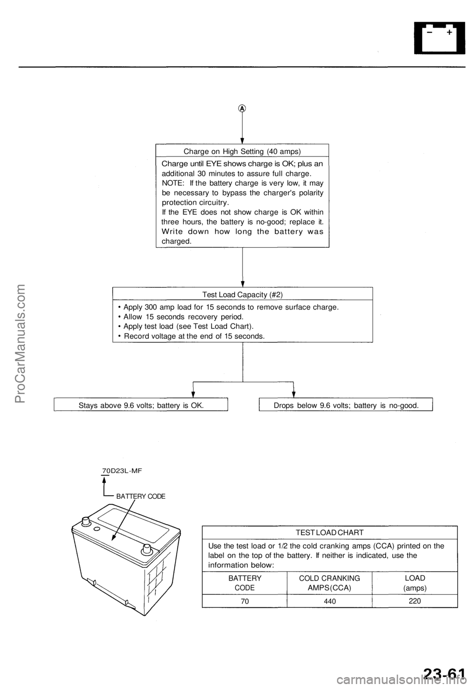
Charge on High Setting (40 amps)
Charge until EYE shows charge is OK; plus an
additional 30 minutes to assure full charge.
NOTE: If the battery charge is very low, it may
be necessary to bypass the charger's polarity
protection circuitry.
If the EYE does not show charge is OK within
three hours, the battery is no-good; replace it.
Write down how long the battery was
charged.
Test Load Capacity (#2)
Apply 300 amp load for 15 seconds to remove surface charge.
Allow 15 seconds recovery period.
Apply test load (see Test Load Chart).
Record voltage at the end of 15 seconds.
70D23L-MF
BATTERY CODE
TEST LOAD CHART
Use the test load or 1/2 the cold cranking amps (CCA) printed on the
label on the top of the battery. If neither is indicated, use the
information below:
BATTERY
CODE
70
COLD CRANKING
AMPS (CCA)
440
LOAD
(amps)
220
Drops below 9.6 volts; battery is no-good.
Stays above 9.6 volts; battery is OK.ProCarManuals.com
Page 1556 of 1771
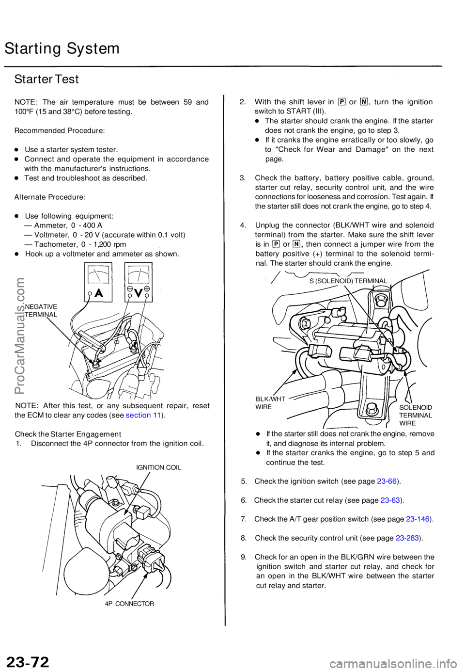
Starting Syste m
Starter Tes t
NOTE : Th e ai r temperatur e mus t b e betwee n 5 9 an d
100° F (1 5 an d 38°C ) befor e testing .
Recommende d Procedure :
Use a starte r syste m tester .
Connec t an d operat e th e equipmen t i n accordanc e
wit h th e manufacturer' s instructions .
Tes t an d troubleshoo t a s described .
Alternate Procedure :
Use followin g equipment :
— Ammeter , 0 - 400 A
— Voltmeter , 0 - 20 V (accurat e withi n 0. 1 volt )
— Tachometer , 0 - 1,20 0 rp m
Hoo k u p a voltmete r an d ammete r a s shown .
NEGATIV ETERMINA L
NOTE: Afte r thi s test , o r an y subsequen t repair , rese t
th e EC M to clea r an y code s (se e sectio n 11 ).
Chec k th e Starte r Engagemen t
1 . Disconnec t th e 4 P connecto r fro m th e ignitio n coil .
IGNITIO N COI L
4P CONNECTO R
2. Wit h th e shif t leve r i n o r , turn th e ignitio n
switch to STAR T (III) .
Th e starte r shoul d cran k th e engine . I f th e starte r
doe s no t cran k th e engine , g o to ste p 3 .
I f i t crank s th e engin e erraticall y o r to o slowly , g o
t o "Chec k fo r Wea r an d Damage " o n th e nex t
page .
3. Chec k th e battery , batter y positiv e cable , ground ,
starte r cu t relay , securit y contro l unit , an d th e wir e
connection s fo r loosenes s an d corrosion . Tes t again . I f
th e starte r stil l doe s no t cran k th e engine , g o to ste p 4 .
4 . Unplu g th e connecto r (BLK/WH T wir e an d solenoi d
terminal ) fro m th e starter . Mak e sur e th e shif t leve r
is i n o r , then connec t a jumpe r wir e fro m th e
batter y positiv e (+ ) termina l t o th e solenoi d termi -
nal . Th e starte r shoul d cran k th e engine .
I f th e starte r stil l doe s no t cran k th e engine , remov e
it , an d diagnos e it s interna l problem .
I f th e starte r crank s th e engine , g o t o ste p 5 an d
continu e th e test .
5 . Chec k th e ignitio n switc h (se e pag e 23-66 ).
6 . Chec k th e starte r cu t rela y (se e pag e 23-63 ).
7 . Chec k th e A/ T gea r positio n switc h (se e pag e 23-146 ).
8 . Chec k th e securit y contro l uni t (se e pag e 23-283 ).
9 . Chec k fo r a n ope n in th e BLK/GR N wir e betwee n th e
ignitio n switc h an d starte r cu t relay , an d chec k fo r
a n ope n i n th e BLK/WH T wir e betwee n th e starte r
cu t rela y an d starter .
SOLENOI DTERMINA LWIRE
BLK/WH TWIRE
S (SOLENOID ) TERMINA L
ProCarManuals.com