Page 1557 of 1771

Check for Wear and Damage
The starter should crank the engine smoothly and steadily.
If the starter engages, but cranks the engine erratically,
remove it, and inspect the starter drive gear and torque
converter ring gear for damage.
Check the drive gear overrunning clutch for binding or
slipping when the armature is rotated with the drive
gear held. If the clutch is damaged, replace the clutch
assembly.
Check Cranking Voltage and Current Draw
Cranking voltage should be no less than 8.5 volts.
Current draw should be no more than 380 amperes.
If cranking voltage is too low, or current draw too high,
check for:
Dead or low battery
Open circuit in starter armature commutator segments
Starter armature dragging
Shorted armature winding
Excessive drag in engine
Check Cranking rpm
Engine speed during cranking should be above 100 rpm.
If speed is too low, check for:
Loose battery or starter terminals
Excessively worn starter brushes
Open circuit in commutator segments
Dirty or damaged helical spline or drive gear
Defective drive gear overrunning clutch
Check Starter Disengagement
With the shift lever in turn the ignition switch to
"START (III)", and release to "ON (II)". The starter drive
gear should disengage from the drive plate/ring gear
when you release the key.
If the drive gear hangs up on the drive plate/ring gear,
check for:
• Solenoid plunger and switch malfunction
• Dirty drive gear assembly or damaged overrunning
clutchProCarManuals.com
Page 1558 of 1771
Starter Solenoid Test
1. Make sure you have the anti-theft code for the
radio, then write down the frequencies for the
radio's preset buttons.
2. Disconnect the battery negative cable, then discon-
nect the positive cable.
3. Check the hold-in coil for continuity between the S
terminal and the armature housing (ground). The
coil is OK if there is continuity.
4. Check the pull-in coil for continuity between the S and
M terminals. The coil is OK if there is continuity.ProCarManuals.com
Page 1559 of 1771

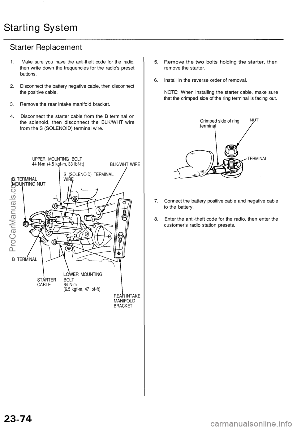
Starting Syste m
Starter Replacemen t
1. Mak e sur e yo u hav e th e anti-thef t cod e fo r th e radio ,
the n writ e dow n th e frequencie s fo r th e radio' s prese t
buttons .
2 . Disconnec t th e batter y negativ e cable , the n disconnec t
th e positiv e cable .
3 . Remov e th e rea r intak e manifol d bracket .
4 . Disconnec t th e starte r cabl e fro m th e B termina l o n
th e solenoid , the n disconnec t th e BLK/WH T wir e
fro m th e S (SOLENOID ) termina l wire .
UPPE R MOUNTIN G BOL T
4 4 N- m (4. 5 kgf-m , 3 3 Ibf-ft )
BLK/WHT WIR E
B TERMINA L
MOUNTING NU T
S (SOLENOID ) TERMINA LWIRE
B TERMINA L
LOWER MOUNTIN G
STARTER BOL T
CABL E 6 4 N- m
(6. 5 kgf-m , 4 7 Ibf-ft )
REAR INTAK E
MANIFOL DBRACKET
5. Remov e th e tw o bolt s holdin g th e starter , the n
remov e th e starter .
6 . Instal l i n th e revers e orde r o f removal .
NOTE : Whe n installin g th e starte r cable , mak e sur e
tha t th e crimpe d sid e o f th e rin g termina l i s facin g out .
Crimpe d sid e o f rin gtermina l
NUT
TERMINA L
7. Connec t th e batter y positiv e cabl e an d negativ e cabl e
t o th e battery .
8 . Ente r th e anti-thef t cod e fo r th e radio , the n ente r th e
customer' s radi o statio n presets .
ProCarManuals.com
Page 1560 of 1771
Starter Overhau l
CAUTION: Befor e removin g th e starter , disconnec t th e
negativ e cabl e fro m th e battery .
STARTE R
SOLENOI D
SOLENOI D
LEVER
STARTE RSOLENOI DTest, pag e 23-7 3
OVERRUNNIN GCLUTCH ASSEMBL Y
RUBBE R SEA L
MOLYBDENU M
DISULFID E
TERMINA L COVE R
BRUSH HOLDE R
Test , pag e 23-7 8
ARMATUR EInspection an d
Test , pag e 23-7 6
ARMATUR E HOUSIN G
wit h PERMANEN T
MAGNET
GEAR HOUSIN G
VEN T
TUBE
S TERMINA L WIR E
GEAR HOUSIN G
COVER
OVERRUNNIN GCLUTCH ASSEMBL YInspection, pag e 23-7 9
GASKE
T
BRUSH HOLDE R
ARMATUR E
SOLENOIDLEVER
BRUS HInspection ,
pag e 23-7 8
BRACKE T
END COVE R
MOLYBDENU MDISULFIDE
ProCarManuals.com
Page 1565 of 1771

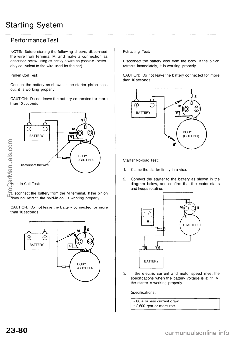
Starting System
Performance Test
NOTE: Before starting the following checks, disconnect
the wire from terminal M, and make a connection as
described below using as heavy a wire as possible (prefer-
ably equivalent to the wire used for the car).
Pull-in Coil Test:
Connect the battery as shown. If the starter pinion pops
out, it is working properly.
CAUTION: Do not leave the battery connected for more
than 10 seconds.
Disconnect the wire.
Hold-in Coil Test:
Disconnect the battery from the M terminal. If the pinion
does not retract, the hold-in coil is working properly.
CAUTION: Do not leave the battery connected for more
than 10 seconds.
Retracting Test:
Disconnect the battery also from the body. If the pinion
retracts immediately, it is working properly.
CAUTION: Do not leave the battery connected for more
than 10 seconds.
Starter No-load Test:
1. Clamp the starter firmly in a vise.
2. Connect the starter to the battery as shown in the
diagram below, and confirm that the motor starts
and keeps rotating.
3. If the electric current and motor speed meet the
specifications when the battery voltage is at 11 V,
the starter is working properly.
Specifications:
80 A or less current draw
2,600 rpm or more rpm
BATTERY
BODY
(GROUND)
BATTERY
STARTER
BODY
(GROUND)
BATTERY
BODY
(GROUND)
BATTERYProCarManuals.com
Page 1569 of 1771
Idle Spee d Chec k
1. Star t th e engine . Hol d th e engin e a t 3,00 0 rp m wit h
no loa d (shif t leve r i n o r ) unti l th e radiato r fa n
come s on , the n le t i t idle .
2 . Connec t a tachomete r t o th e tes t tachomete r connec -
tor.
TES T TACHOMETE R CONNECTO R
TES T TACHOMETE R CONNECTO R
BATTERY
Idle speed : 70 0 ± 5 0 rp m wit h shif t leve r i n positio n
or an d electrica l system s turne d off .
3 . Adjus t th e idl e spee d if necessar y (se e sectio n 11 ).
Distributo r Remova l
1. Disconnec t th e ignitio n wire s fro m th e distributo r
ignition (Dl ) cap .
MOUNTIN GBOLTS
2. Remov e th e distributo r mountin g bolts , the n remov e
th e distributo r fro m th e cylinde r head .
CLIP
TACHOMETE R
ProCarManuals.com
Page 1597 of 1771
Speedometer/Trip Meter/Odometer
Troubleshooting
NOTE:
The numbers in the table show the troubleshooting sequence.
If necessary, replace the speedometer, trip meter, and odometer as a unit.
VSS Input Test
Trml
Wire
Test condition
Test: Desired result
Possible cause if result is not obtained
1
2
3
BLK
YEL
ORN
Under all conditions
Ignition switch ON (II)
Ignition switch ON (II)
Check for continuity to ground:
There should be continuity.
Check for voltage to ground:
There should be battery voltage.
Check for voltage to ground:
There should be about 5 V or more.
• Poor ground (G101)
• An open in the wire
• Blown No. 1 (10 A) fuse in the
under-dash fuse/relay box
• Short to ground
• An open in the wire
• Short to ground
• An open in the wire
NOTE: A short to ground in the ORN wire can be caused by a short in any component connected to it.ProCarManuals.com
Page 1696 of 1771
Troubleshooting (With Keyless Entry) ('98 model)
NOTE: The numbers in the table show the troubleshooting sequence.
CAUTION: To prevent damage to the motor, apply battery voltage only momentarily.
NOTE:
When the remote transmitter button is pressed the first time, only the driver's door will unlock. When the button is
pressed the second time, all the doors will unlock.
The doors will relock automatically after 20 seconds if a door is not opened, or the key is out of the ignition switch.
The keyless entry system will not lock the doors when the key is in the ignition switch.ProCarManuals.com