1995 ACURA TL battery
[x] Cancel search: batteryPage 668 of 1771
SRS Uni t
Replacemen t
CAUTION:
Durin g installatio n o r replacement , d o no t bum p
(impac t wrench , hamme r etc. ) th e are a nea r th e SR S
unit .
D o no t damag e th e SR S uni t terminal s o r connec -
tors.
Do no t disassembl e th e SR S unit ; i t ha s n o service -
abl e parts .
Stor e th e SR S uni t i n a clean , dr y area .
D o no t us e an y SR S uni t whic h ha s bee n subjecte d
t o wate r damag e o r show s sign s o f bein g droppe d o r
improperl y handled , suc h a s dents , crack s o r defor -
mation .
1 . Mak e sur e yo u hav e th e anti-thef t cod e fo r th e
radio , the n writ e dow n th e frequencie s fo r th e
radio' s prese t buttons .
2 . Disconnec t th e batter y negativ e cable , the n discon -
nec t th e positiv e cabl e fro m th e battery , an d wai t a t
leas t thre e minutes .
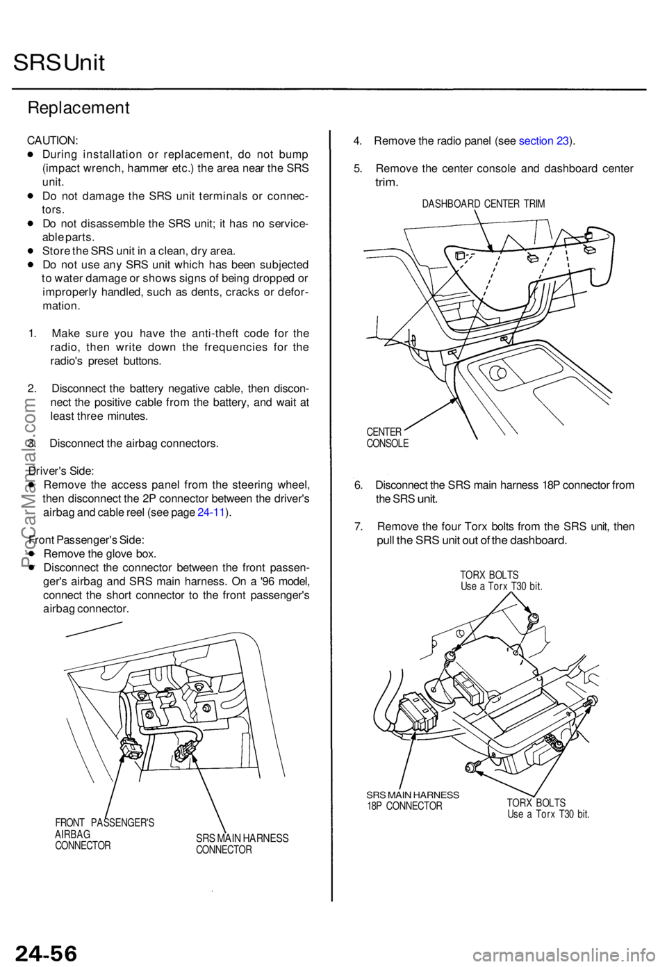
3 . Disconnec t th e airba g connectors .
Driver' s Side :
Remov e th e acces s pane l fro m th e steerin g wheel ,
the n disconnec t th e 2 P connecto r betwee n th e driver' s
airba g an d cabl e ree l (se e pag e 24-11 ).
Fron t Passenger' s Side :
Remov e th e glov e box .
Disconnec t th e connecto r betwee n th e fron t passen -
ger' s airba g an d SR S mai n harness . O n a '9 6 model ,
connec t th e shor t connecto r t o th e fron t passenger' s
airba g connector .
FRONT PASSENGER' S
AIRBA G
CONNECTO R
SRS MAI N HARNES SCONNECTO R
4. Remov e th e radi o pane l (se e sectio n 23 ).
5 . Remov e th e cente r consol e an d dashboar d cente r
trim.
DASHBOAR D CENTE R TRI M
CENTE R
CONSOL E
6. Disconnec t th e SR S mai n harnes s 18 P connecto r fro m
th e SR S
unit .
7. Remov e th e fou r Tor x bolt s fro m th e SR S unit , the n
pull th e SR S uni t ou t o f th e dashboard .
TORX BOLT S
Us e a Tor x T3 0 bit .
SRS MAI N HARNES S18P CONNECTO R TOR
X BOLT SUse a Tor x T3 0 bit .
ProCarManuals.com
Page 669 of 1771
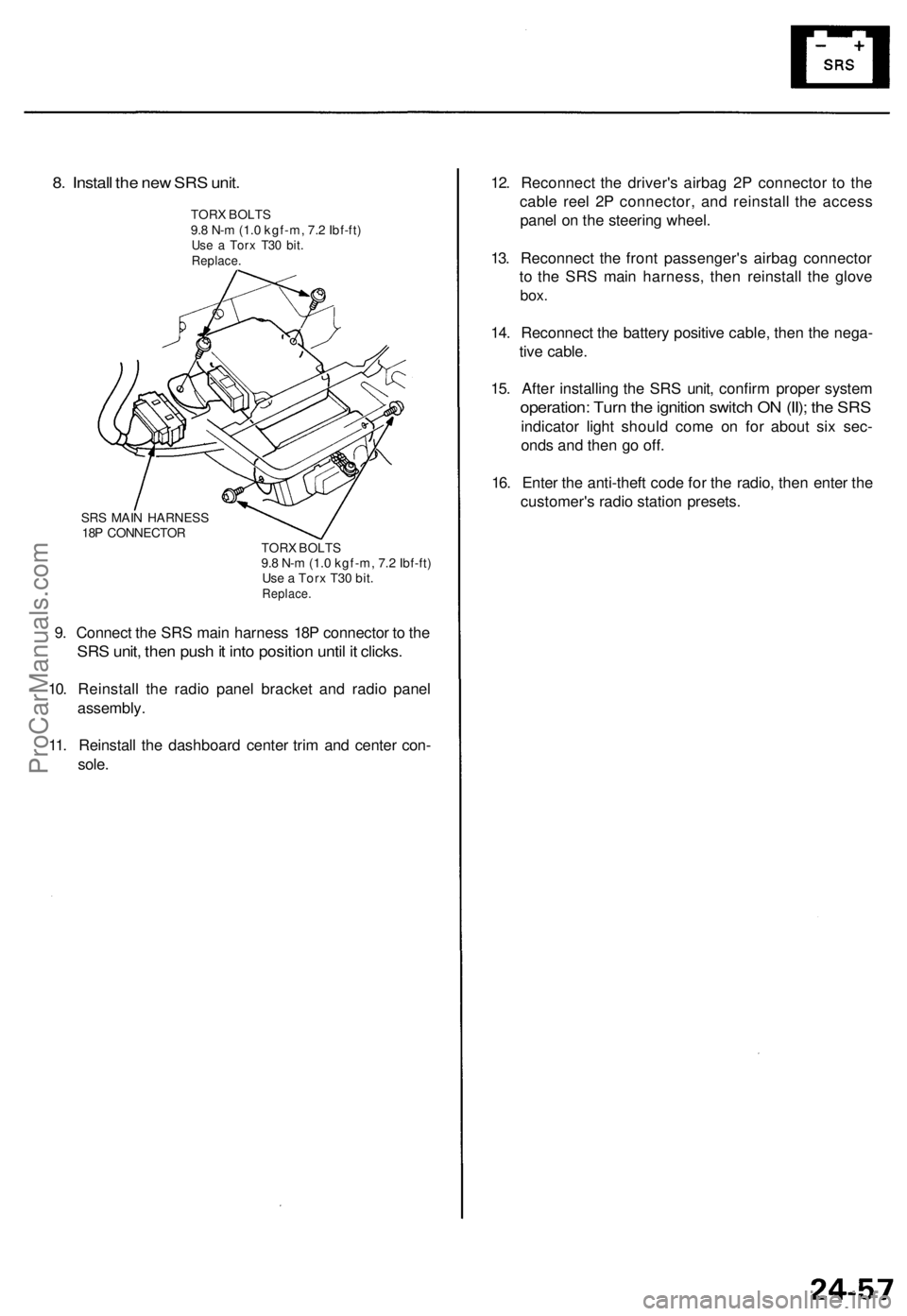
8. Install the new SRS unit.
TORX BOLTS
9.8 N-m (1.0 kgf-m, 7.2 Ibf-ft)
Use a Torx T30 bit.
Replace.
SRS MAIN HARNESS
18P CONNECTOR
TORX BOLTS
9.8 N-m (1.0 kgf-m, 7.2 Ibf-ft)
Use a Torx T30 bit.
Replace.
9. Connect the SRS main harness 18P connector to the
SRS unit, then push it into position until it clicks.
10. Reinstall the radio panel bracket and radio panel
assembly.
11. Reinstall the dashboard center trim and center con-
sole.
12. Reconnect the driver's airbag 2P connector to the
cable reel 2P connector, and reinstall the access
panel on the steering wheel.
13. Reconnect the front passenger's airbag connector
to the SRS main harness, then reinstall the glove
box.
14. Reconnect the battery positive cable, then the nega-
tive cable.
15. After installing the SRS unit, confirm proper system
operation: Turn the ignition switch ON (II); the SRS
indicator light should come on for about six sec-
onds and then go off.
16. Enter the anti-theft code for the radio, then enter the
customer's radio station presets.ProCarManuals.com
Page 683 of 1771
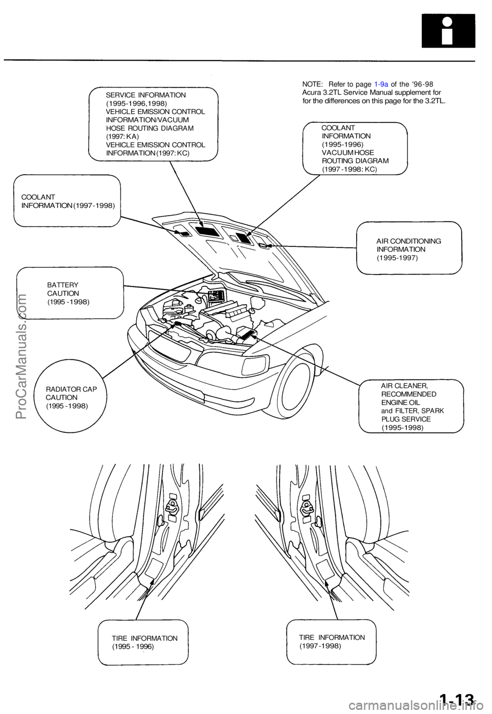
SERVICE INFORMATIO N(1995-1996,1998 )VEHICLE EMISSIO N CONTRO LINFORMATION/VACUU MHOSE ROUTIN G DIAGRA M(1997: KA )VEHICL E EMISSIO N CONTRO LINFORMATIO N (1997 : KC )
COOLAN TINFORMATIO N(1995-1996)VACUUM HOS EROUTIN G DIAGRA M(1997 -1998 : KC)
COOLAN TINFORMATIO N (199 7 -1998 )
AIR CONDITIONIN G
INFORMATIO N
(1995-1997 )
BATTERYCAUTION(1995 -1998 )
AIR CLEANER ,RECOMMENDE DENGINE OI Land FILTER , SPAR KPLUG SERVIC E(1995-1998 )
TIRE INFORMATIO N(1995 - 1996 )TIRE INFORMATIO N(1997 -1998 )
RADIATO R CA PCAUTIO N
(199 5 -1998 )
NOTE: Refe r t o page 1-9a of th e '9 6-9 8 Acura 3.2TL Servic e Manual supplement forfor the differences on this page for the 3.2TL.
ProCarManuals.com
Page 719 of 1771
Engine Removal/Installation
Removal
• Make sure jacks and safety stands are placed properly
and hoist brackets are attached to the correct positions
on the engine.
• Make sure the car will not roll off stands and fall
while you are working under it.
CAUTION:
• Use fender covers to avoid damaging painted sur-
face.
• Unplug the wiring connectors carefully while holding
the connector portion to avoid damage.
• Mark all wiring and hoses to avoid misconnection.
Also, be sure that they do not contact other wiring
or hoses or interfere with other parts.
1. Secure the hood open as far as possible.
2. Make sure you have the anti-theft code for the radio,
then write down the frequencies for the radio's pre-
set buttons.
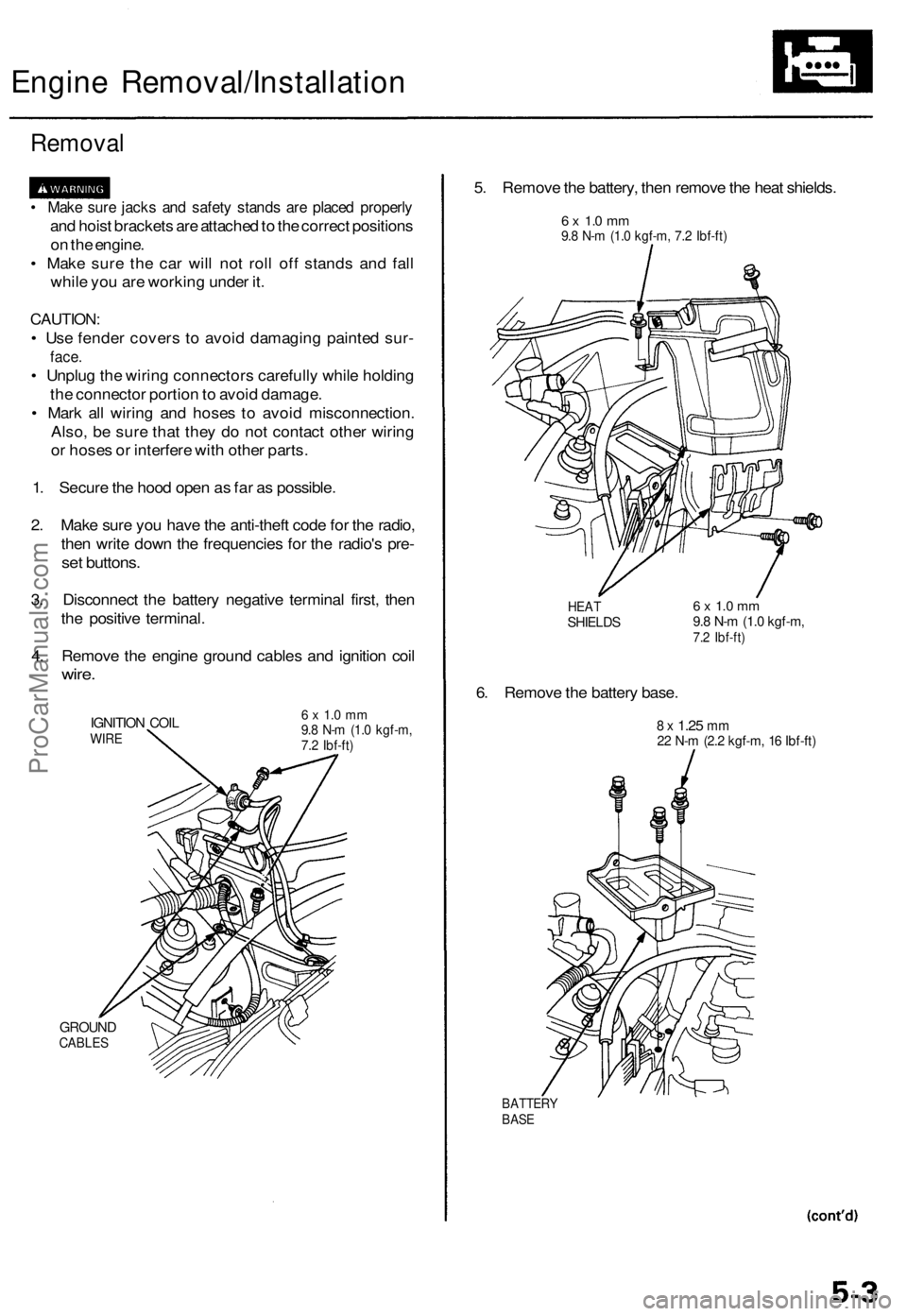
3. Disconnect the battery negative terminal first, then
the positive terminal.
4. Remove the engine ground cables and ignition coil
wire.
IGNITION COIL
WIRE
GROUND
CABLES
6 x 1.0 mm
9.8 N-m (1.0 kgf-m,
7.2 Ibf-ft)
5. Remove the battery, then remove the heat shields.
6 x 1.0 mm
9.8 N-m (1.0 kgf-m, 7.2 Ibf-ft)
HEAT
SHIELDS
6. Remove the battery base.
6 x 1.0 mm
9.8 N-m (1.0 kgf-m,
7.2 Ibf-ft)
8 x
1.25
mm
22 N-m (2.2 kgf-m, 16 Ibf-ft)
BATTERY
BASEProCarManuals.com
Page 720 of 1771
Engine Removal/Installation
Removal (cont'd)
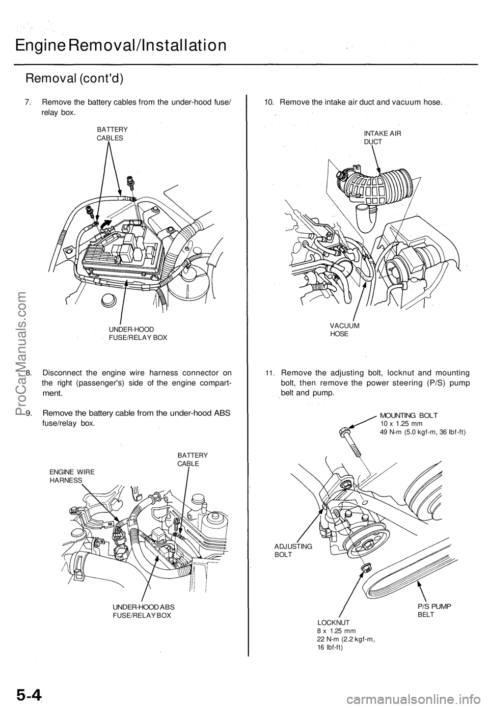
7. Remove the battery cables from the under-hood fuse/
relay box.
BATTERY
CABLES
8.
9.
UNDER-HOOD
FUSE/RELAY BOX
Disconnect the engine wire harness connector on
the right (passenger's) side of the engine compart-
ment.
Remove the battery cable from the under-hood ABS
fuse/relay box.
BATTERY
CABLE
ENGINE WIRE
HARNESS
UNDER-HOOD ABS
FUSE/RELAY BOX
10. Remove the intake air duct and vacuum hose.
INTAKE AIR
DUCT
11.
VACUUM
HOSE
Remove the adjusting bolt, locknut and mounting
bolt, then remove the power steering (P/S) pump
belt and pump.
MOUNTING BOLT
10 x
1.25
mm
49 N-m (5.0 kgf-m, 36 Ibf-ft)
ADJUSTING
BOLT
P/S PUMP
BELT
LOCKNUT
8 x
1.25
mm
22 N-m (2.2 kgf-m,
16 Ibf-ft)ProCarManuals.com
Page 750 of 1771
Cylinder Hea d
Remova l
Engine remova l i s no t require d fo r thi s procedure .
Mak e sur e jack s an d safet y stand s ar e
place d properl y an d hois t bracket s ar e attache d to cor -
rec t positio n o n th e engine .
CAUTION :
• Us e fende r cover s t o avoi d damagin g painte d sur -
faces .
• Unplu g th e wirin g connector s carefull y whil e holdin g
th e connecto r portio n to avoi d damage .
• T o avoi d damagin g th e cylinde r head , wai t unti l th e
engin e coolan t temperatur e drop s belo w 100° F
(38°C ) befor e loosenin g th e retainin g bolts .
NOTE :
• Mar k al l wirin g an d hose s t o avoi d misconnection .
Also , b e sur e tha t the y d o no t contac t othe r wirin g o r
hoses , o r interfer e wit h othe r parts .
• Inspec t th e timin g bel t befor e removin g th e cylinde r
head .
• Tur n th e crankshaf t pulle y s o tha t th e No . 1 pisto n i s
a t to p dea d cente r (se e pag e 6-12 ).
1 . Mak e sur e yo u hav e th e anti-thef t cod e fo r th e radio ,
the n writ e dow n th e frequencie s fo r th e radio' s pre -
se t buttons .
2 . Disconnec t th e negativ e termina l fro m th e battery .
3 . Drai n th e engin e coolan t (se e pag e 10-5 ).
Remov e th e radiato r cap to spee d draining .
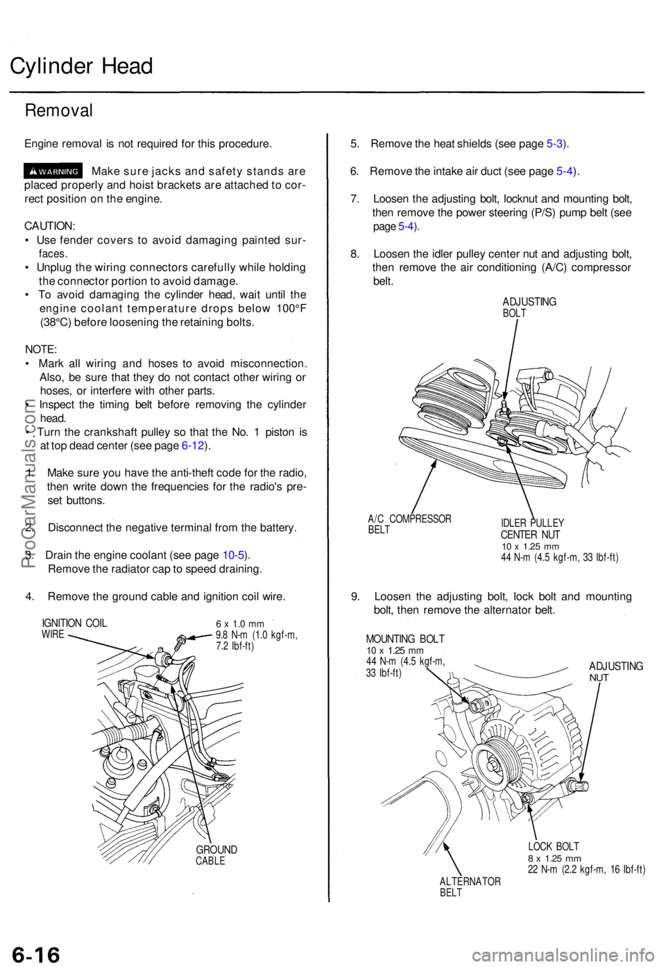
4 . Remov e th e groun d cabl e an d ignitio n coi l wire .
IGNITIO N COI LWIRE6 x 1. 0 m m9.8 N- m (1. 0 kgf-m ,
7. 2 Ibf-ft )
GROUN DCABLE
5. Remov e th e hea t shield s (se e pag e 5-3 ).
6 . Remov e th e intak e ai r duc t (se e pag e 5-4 ).
7 . Loose n th e adjustin g bolt , locknu t an d mountin g bolt ,
the n remov e th e powe r steerin g (P/S ) pum p bel t (se e
page 5-4 ).
8 . Loose n th e idle r pulle y cente r nu t an d adjustin g bolt ,
the n remov e th e ai r conditionin g (A/C ) compresso r
belt .
ADJUSTIN GBOLT
A/ C COMPRESSO R
BELTIDLE R PULLE YCENTER NU T10 x 1.2 5 mm44 N- m (4. 5 kgf-m , 3 3 Ibf-ft )
9. Loose n th e adjustin g bolt , loc k bol t an d mountin g
bolt , the n remov e th e alternato r belt .
MOUNTIN G BOL T10 x 1.2 5 mm44 N- m (4. 5 kgf-m ,
3 3 Ibf-ft )ADJUSTIN GNUT
LOC K BOL T8 x 1.2 5 mm22 N- m (2. 2 kgf-m , 1 6 Ibf-ft )
ALTERNATO R
BELT
ProCarManuals.com
Page 820 of 1771
HO2S
Replacemen t
Primary HO2S :
1 . Mak e sur e yo u hav e th e anti-thef t cod e fo r th e
radio , the n writ e dow n th e frequencie s fo r th e
radio' s prese t buttons .
2 . Disconnec t th e batter y negativ e termina l first , the n
th e positiv e terminal .
3 . Remov e th e battery , the n remov e th e hea t shield s
(se e pag e 5-3 ).
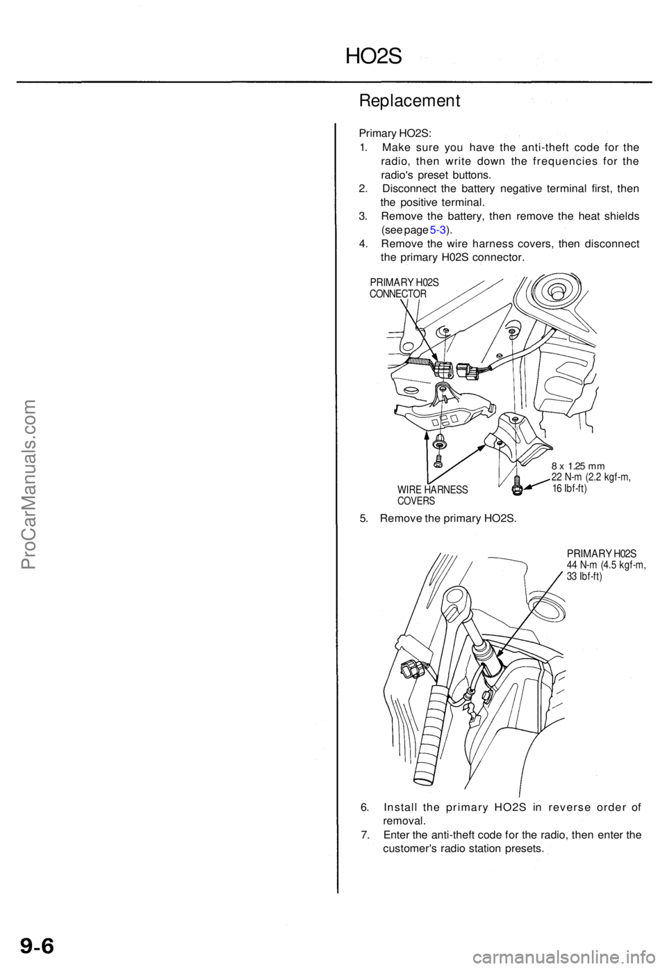
4 . Remov e th e wir e harnes s covers , the n disconnec t
th e primar y H02 S connector .
PRIMARY H02 SCONNECTO R
WIR E HARNES S
COVERS
5. Remov e th e primar y HO2S .
8 x 1.2 5 mm22 N- m (2. 2 kgf-m ,
1 6 Ibf-ft )
PRIMAR Y H02 S44 N- m (4. 5 kgf-m ,
3 3 Ibf-ft )
6. Instal l th e primar y HO2 S i n revers e orde r o f
removal .
7. Ente r th e anti-thef t cod e fo r th e radio , the n ente r th e
customer' s radi o statio n presets .
ProCarManuals.com
Page 877 of 1771
PGM-FI System
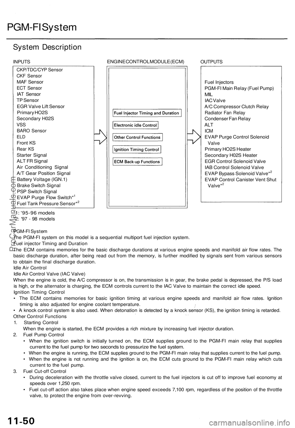
System Description
INPUTS
ENGINE CONTROL MODULE (ECM)
OUTPUTS
Fuel Injectors
PGM-FI Main Relay (Fuel Pump)
MIL
IAC Valve
A/C Compressor Clutch Relay
Radiator Fan Relay
Condenser Fan Relay
ALT
ICM
EVAP Purge Control Solenoid
Valve
Primary HO2S Heater
Secondary H02S Heater
EGR Control Solenoid Valve
IAB Control Solenoid Valve
EVAP Bypass Solenoid Valve*2
EVAP Control Canister Vent Shut
Valve*2
*1: '95-96 models
*2: '97 - 98 models
PGM-FI System
The PGM-FI system on this model is a sequential multiport fuel injection system.
Fuel injector Timing and Duration
The ECM contains memories for the basic discharge durations at various engine speeds and manifold air flow rates. The
basic discharge duration, after being read out from the memory, is further modified by signals sent from various sensors
to obtain the final discharge duration.
Idle Air Control
Idle Air Control Valve (IAC Valve)
When the engine is cold, the A/C compressor is on, the transmission is in gear, the brake pedal is depressed, the P/S load
is high, or the alternator is charging, the ECM controls current to the IAC Valve to maintain the correct idle speed.
Ignition Timing Control
• The ECM contains memories for basic ignition timing at various engine speeds and manifold air flow rates. Ignition
timing is also adjusted for engine coolant temperature.
• A knock control system is also used. When detonation is detected by a knock sensor (KS), the ignition timing is retarded.
Other Control Functions
1. Starting Control
When the engine is started, the ECM provides a rich mixture by increasing fuel injector duration.
2. Fuel Pump Control
• When the ignition switch is initially turned on, the ECM supplies ground to the PGM-FI main relay that supplies
current to the fuel pump for two seconds to pressurize the fuel system.
• When the engine is running, the ECM supplies ground to the PGM-FI main relay that supplies current to the fuel pump.
• When the engine is not running and the ignition is on, the ECM cuts ground to the PGM-FI main relay which cuts
current to the fuel pump.
3. Fuel Cut-off Control
• During deceleration with the throttle valve closed, current to the fuel injectors is cut off to improve fuel economy at
speeds over 1,250 rpm.
• Fuel cut-off action also takes place when engine speed exceeds 7,100 rpm, regardless of the position of the throttle
valve, to protect the engine from over-revving.
CKP/TDC/CYP Sensor
CKF Sensor
MAF Sensor
ECT Sensor
IAT Sensor
TP Sensor
EGR Valve Lift Sensor
Primary HO2S
Secondary H02S
VSS
BARO Sensor
ELD
Front KS
Rear KS
Starter Signal
ALT FR Signal
Air Conditioning Signal
A/T Gear Position Signal
Battery Voltage (IGN.1)
Brake Switch Signal
PSP Switch Signal
EVAP Purge Flow Switch*1
Fuel Tank Pressure Sensor*2ProCarManuals.com