1995 ACURA TL battery
[x] Cancel search: batteryPage 332 of 1771
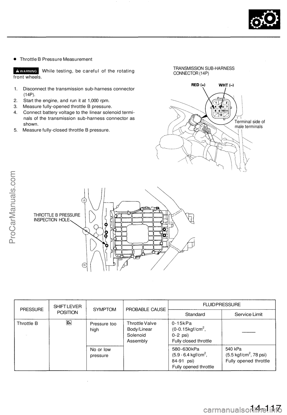
Throttle B Pressure Measurement
While testing, be careful of the rotating
front wheels.
1. Disconnect the transmission sub-harness connector
(14P).
2. Start the engine, and run it at 1,000 rpm.
3. Measure fully-opened throttle B pressure.
4. Connect battery voltage to the linear solenoid termi-
nals of the transmission sub-harness connector as
shown.
5. Measure fully-closed throttle B pressure.
TRANSMISSION SUB-HARNESS
CONNECTOR (14P)
Terminal side of
male terminals
THROTTLE B PRESSURE
INSPECTION HOLE
PRESSURE
Throttle B
SHIFT LEVER
POSITION
SYMPTOM
Pressure too
high
No or low
pressure
PROBABLE CAUSE
Throttle Valve
Body/Linear
Solenoid
Assembly
FLUID PRESSURE
Standard
0-15kPa
(0-0.15kgf/cm2,
0-2
psi)
Fully closed throttle
580
-
630
kPa
(5.9 - 6.4 kgf/cm2,
84-91 psi)
Fully opened throttle
Service Limit
540 kPa
(5.5 kgf/cm2, 78 psi)
Fully opened throttle
14-117ProCarManuals.com
Page 334 of 1771
![ACURA TL 1995 Service Repair Manual
6. Disconnect the transmission sub-harness connector (14P).
7. Start the engine, and run it at 2,000 rpm.
TRANSMISSION SUB-HARNESS
CONNECTOR (14P)
8. Shift to the [HI or [P] position, and measure ACURA TL 1995 Service Repair Manual
6. Disconnect the transmission sub-harness connector (14P).
7. Start the engine, and run it at 2,000 rpm.
TRANSMISSION SUB-HARNESS
CONNECTOR (14P)
8. Shift to the [HI or [P] position, and measure](/manual-img/32/56993/w960_56993-333.png)
6. Disconnect the transmission sub-harness connector (14P).
7. Start the engine, and run it at 2,000 rpm.
TRANSMISSION SUB-HARNESS
CONNECTOR (14P)
8. Shift to the [HI or [P] position, and measure line pressure at fully-opened throttle.
9. Connect battery voltage to the linear solenoid terminals of the transmission sub-harness connector as shown.
10. Measure line pressure at fully-closed throttle.
If line pressure is out of specification, check and repair the probable cause in the table below.
PRESSURE
Line
SHIFT LEVER
POSITION
or
SYMPTOM
No (or
low)
line pressure
PROBABLE CAUSE
Torque converter,
ATF pump, pres-
sure regulator.
torque converter
check valve
FLUID PRESSURE
Standard
520 kPa
(5.3 kgf/cm2, 75 psi)
Fully closed throttle
|
910 kPa
(9.3 kgf/cm2, 130 psi)
Fully opened throttle
Service Limit
500 kPa
(5.1 kgf/cm2, 73 psi)
Fully closed throttle
790 kPa
(8.1 kgf/cm2, 120 psi)
Fully opened throttle
11. Stop the engine, and connect the transmission sub-harness connector (14P).
12. Disconnect the special tool from line pressure inspection hole, and connect the special tool to each inspection hole.
13. Start the engine, and run it at 2,000 rpm.
(cont'd)ProCarManuals.com
Page 339 of 1771
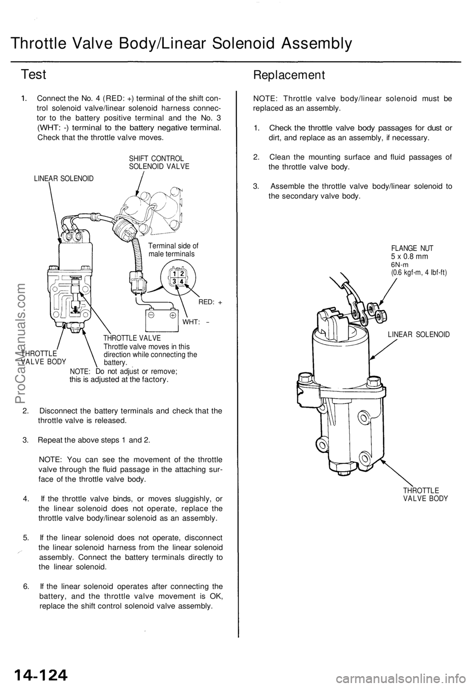
Throttle Valv e Body/Linea r Solenoi d Assembl y
Test
Connec t th e No . 4 (RED : + ) termina l o f th e shif t con -
tro l solenoi d valve/linea r solenoi d harnes s connec -
to r t o th e batter y positiv e termina l an d th e No . 3
(WHT : - ) termina l t o th e batter y negativ e terminal .
Check tha t th e throttl e valv e moves .
SHIFT CONTRO LSOLENOID VALV E
LINEAR SOLENOI D
THROTTL EVALVE BOD Y
Termina l sid e o fmal e terminal s
RED: +
WHT : -
NOTE :
THROTTL E VALV EThrottle valv e move s i n thi sdirectio n whil e connectin g th ebattery .
Do no t adjus t o r remove ;this is adjuste d a t th e factory .
2 . Disconnec t th e batter y terminal s an d chec k tha t th e
throttl e valv e i s released .
3 . Repea t th e abov e step s 1 an d 2 .
NOTE : Yo u ca n se e th e movemen t o f th e throttl e
valv e throug h th e flui d passag e i n th e attachin g sur -
fac e o f th e throttl e valv e body .
4 . I f th e throttl e valv e binds , o r move s sluggishly , o r
th e linea r solenoi d doe s no t operate , replac e th e
throttl e valv e body/linea r solenoi d a s a n assembly .
5 . I f th e linea r solenoi d doe s no t operate , disconnec t
th e linea r solenoi d harnes s fro m th e linea r solenoi d
assembly . Connec t th e batter y terminal s directl y t o
th e linea r solenoid .
6 . I f th e linea r solenoi d operate s afte r connectin g th e
battery , an d th e throttl e valv e movemen t i s OK ,
replac e th e shif t contro l solenoi d valv e assembly .
Replacemen t
NOTE: Throttl e valv e body/linea r solenoi d mus t b e
replace d a s a n assembly .
1. Chec k th e throttl e valv e bod y passage s fo r dus t o r
dirt , an d replac e a s a n assembly , i f necessary .
2 . Clea n th e mountin g surfac e an d flui d passage s o f
th e throttl e valv e body .
3 . Assembl e th e throttl e valv e body/linea r solenoi d t o
th e secondar y valv e body .
FLANG E NU T5 x 0. 8 m m6N- m(0.6 kgf-m , 4 Ibf-ft )
LINEA R SOLENOI D
THROTTLEVALVE BOD Y
ProCarManuals.com
Page 341 of 1771
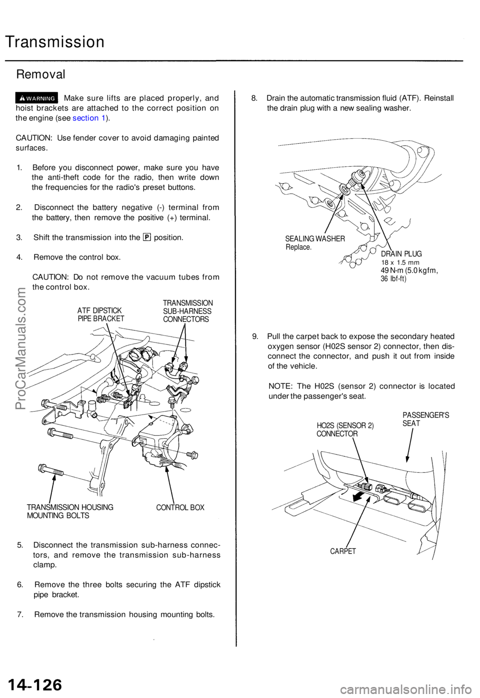
Transmission
Removal
Make sur e lift s ar e place d properly , an d
hois t bracket s ar e attache d t o th e correc t positio n o n
th e engin e (se e sectio n 1 ).
CAUTION : Us e fende r cove r t o avoi d damagin g painte d
surfaces .
1. Befor e yo u disconnec t power , mak e sur e yo u hav e
th e anti-theft code fo r th e radio , the n writ e dow n
th e frequencie s fo r th e radio' s prese t buttons .
2 . Disconnec t th e batter y negativ e (- ) termina l fro m
th e battery , the n remov e th e positiv e (+ ) terminal .
3. Shif t th e transmissio n int o th e position .
4 . Remov e th e contro l box .
CAUTION : D o no t remov e th e vacuu m tube s fro m
th e contro l box .
ATF DIPSTIC KPIPE BRACKE T
TRANSMISSIO N
SUB-HARNES S
CONNECTOR S
TRANSMISSIO N HOUSIN GMOUNTIN G BOLT SCONTRO L BO X
5. Disconnec t th e transmissio n sub-harnes s connec -
tors , an d remov e th e transmissio n sub-harnes s
clamp .
6 . Remov e th e thre e bolt s securin g th e AT F dipstic k
pip e bracket .
7 . Remov e th e transmissio n housin g mountin g bolts . 8
. Drai n th e automati c transmissio n flui d (ATF) . Reinstal l
th e drai n plu g wit h a ne w sealin g washer .
SEALIN G WASHE RReplace.DRAIN PLU G18 x 1. 5 m m49 N- m (5. 0 kgfm ,36 Ibf-ft )
9. Pul l th e carpe t bac k t o expos e th e secondar y heate d
oxyge n senso r (H02 S senso r 2 ) connector , the n dis -
connec t th e connector , an d pus h i t ou t fro m insid e
o f th e vehicle .
NOTE : Th e H02 S (senso r 2 ) connecto r i s locate d
unde r th e passenger' s seat .
HO2S (SENSO R 2 )
CONNECTO R PASSENGER'
SSEAT
CARPE T
ProCarManuals.com
Page 522 of 1771
Troubleshooting Precautions
ABS Indicator Light
1. If the system is OK, the ABS indicator light goes off two seconds after turning the ignition switch ON (II) without start-
ing the engine. After starting the engine, the ABS indicator light comes on again and goes off after two seconds. This
occurs because the ABS control unit is activated by the IG2 power source.
2. The ABS indicator light comes on when the ABS control unit detects a problem in the system. However, even though
the system is normal, the ABS indicator light comes on, too, under the following conditions. To determine the actual
cause of problem, question the customer about the problem, talking the following conditions into consideration.
Only drive wheels rotate
One wheel stuck of drive wheels
Vehicle spin
ABS operate condition continue for long time
Signal disturbance
3. When a problem is detected and the ABS indicator light comes on, there are cases when the indicator light stays on
until the ignition switch is turned OFF, and cases when the indicator light goes off automatically when the system
returns normal. For the DTC 61 and 62, the indicator light goes off automatically when the system returns normal. For
all other codes, the indicator light stays on until the ignition switch is turned OFF.
4. For DTCs 12, 14, 16, 18, 21, 22, 23, 24, 51, 52 and 53, the indicator light goes off when the vehicle is driven again and
the signals are OK after the ignition switch is turned from OFF to ON (II). However, if the DTC is erased, the CPU is
reset and the indicator light goes off right after the engine is started if the signals are OK.
Diagnostic Trouble Code (DTC)
1. The DTC is not memorized if the CPU cannot be activated or the CPU fails and the indicator light comes on.
2. The memory can hold any number of DTCs. However, when the same DTC is detected more than once, the later one
is written over the old one. Therefore, when the same problem is detected repeatedly, it is memorized as one DTC.
3. The DTCs are indicated in the order of ascending number, not in the order they occur.
4. The DTCs are memorized in the EEPROM (non-volatile memory). Therefore, the memorized DTCs cannot be canceled
by disconnecting the battery. Perform the specified procedures to erase the DTCs.
Self-diagnosis
1. The
self-diagnosis
can be
classified
into
two
categories.
• Initial diagnosis: Performed right after the engine starts and until the ABS indicator light goes off.
• Regular diagnosis: Performed right after the initial diagnosis until the ignition switch is turned OFF.
2. When a problem is detected by self-diagnosis, the system
• Turns the ABS indicator light ON
• Memorizes the DTC
• Turns the fail-safe relay OFF
• Stops ABS controlProCarManuals.com
Page 533 of 1771
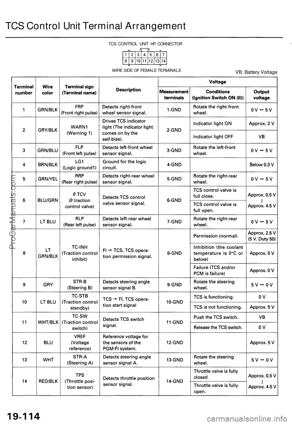
TCS Control Unit Terminal Arrangement
WIRE SIDE OF FEMALE TERMINALS
VB: Battery Voltage
TCS CONTROL UNIT HP CONNECTORProCarManuals.com
Page 534 of 1771
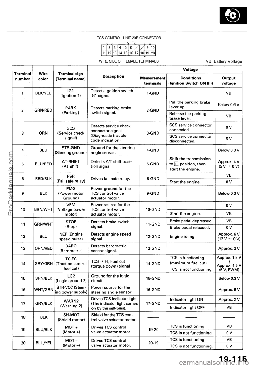
TCS CONTROL UNIT 20P CONNECTOR
WIRE SIDE OF FEMALE TERMINALS
VB: Battery VoltageProCarManuals.com
Page 562 of 1771
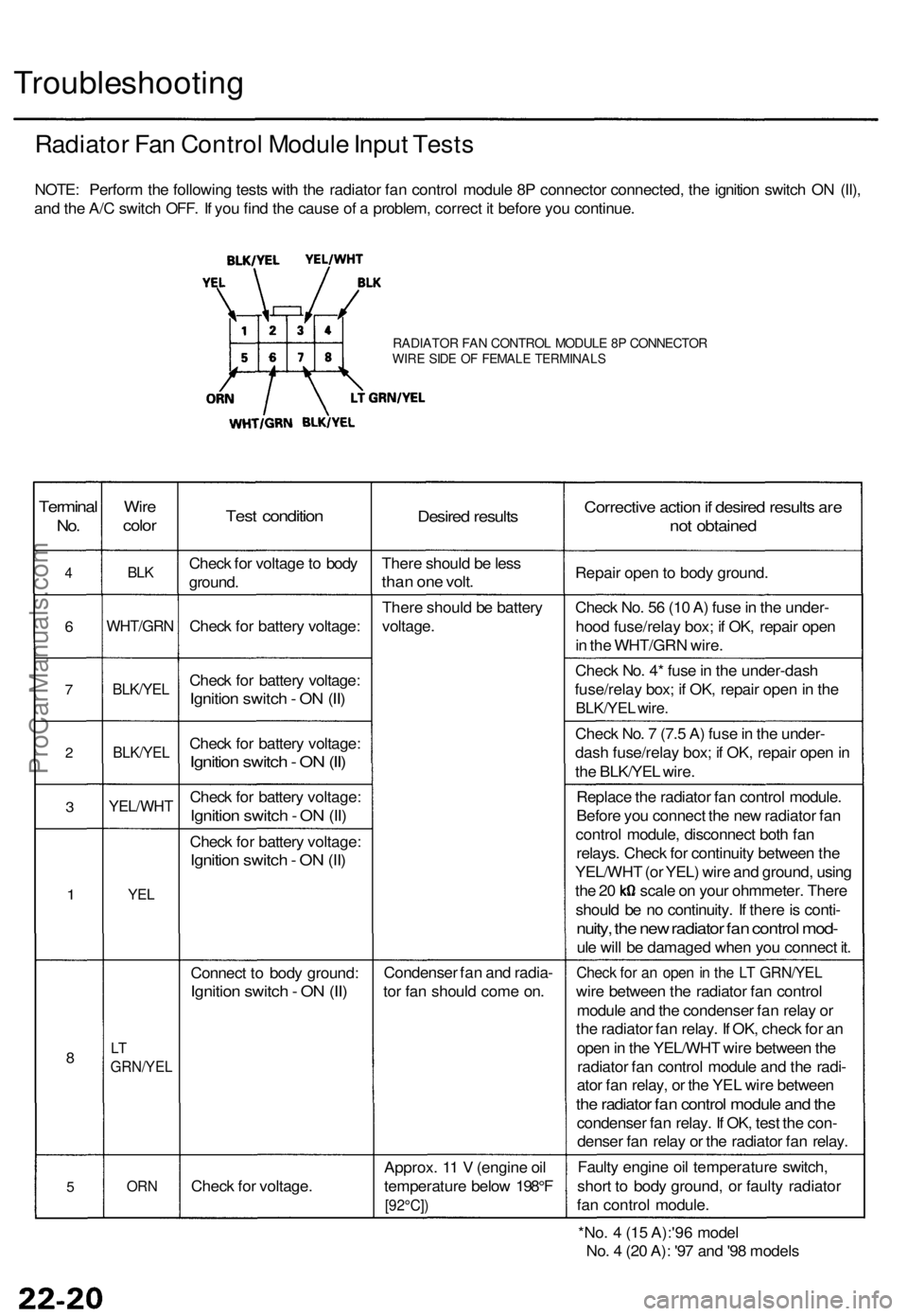
Troubleshooting
Radiator Fan Control Module Input Tests
NOTE: Perform the following tests with the radiator fan control module 8P connector connected, the ignition switch ON (II),
and the A/C switch OFF. If you find the cause of a problem, correct it before you continue.
RADIATOR FAN CONTROL MODULE 8P CONNECTOR
WIRE SIDE OF FEMALE TERMINALS
Terminal
No.
4
6
7
2
3
1
8
5
Wire
color
BLK
WHT/GRN
BLK/YEL
BLK/YEL
YEL/WHT
YEL
LT
GRN/YEL
ORN
Test condition
Check for voltage to body
ground.
Check for battery voltage:
Check for battery voltage:
Ignition switch - ON (II)
Check for battery voltage:
Ignition switch - ON (II)
Check for battery voltage:
Ignition switch - ON (II)
Check for battery voltage:
Ignition switch - ON (II)
Connect to body ground:
Ignition switch - ON (II)
Check for voltage.
Desired results
There should be less
than one volt.
There should be battery
voltage.
Condenser fan and radia-
tor fan should come on.
Approx. 11 V (engine oil
temperature below 198°F
[92°C])
Corrective action if desired results are
not obtained
Repair open to body ground.
Check No. 56 (10 A) fuse in the under-
hood fuse/relay box; if OK, repair open
in the WHT/GRN wire.
Check No. 4* fuse in the under-dash
fuse/relay box; if OK, repair open in the
BLK/YEL wire.
Check No. 7 (7.5 A) fuse in the under-
dash fuse/relay box; if OK, repair open in
the BLK/YEL wire.
Replace the radiator fan control module.
Before you connect the new radiator fan
control module, disconnect both fan
relays. Check for continuity between the
YEL/WHT (or YEL) wire and ground, using
the 20 scale on your ohmmeter. There
should be no continuity. If there is conti-
nuity, the new radiator fan control mod-
ule will be damaged when you connect it.
Check for an open in the LT GRN/YEL
wire between the radiator fan control
module and the condenser fan relay or
the radiator fan relay. If OK, check for an
open in the YEL/WHT wire between the
radiator fan control module and the radi-
ator fan relay, or the YEL wire between
the radiator fan control module and the
condenser fan relay. If OK, test the con-
denser fan relay or the radiator fan relay.
Faulty engine oil temperature switch,
short to body ground, or faulty radiator
fan control module.
*No. 4 (15 A):'96 model
No. 4 (20 A): '97 and '98 modelsProCarManuals.com