1995 ACURA TL battery
[x] Cancel search: batteryPage 564 of 1771
Compressor
Replacemen t
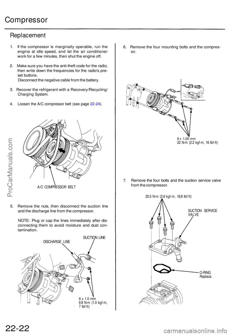
1. I f th e compresso r i s marginall y operable , ru n th e
engin e a t idl e speed , an d le t th e ai r conditione r
wor k fo r a fe w minutes , the n shu t th e engin e off .
2 . Mak e sur e yo u hav e th e anti-thef t cod e fo r th e radio ,
the n writ e dow n th e frequencie s fo r th e radio' s pre -
se t buttons .
Disconnec t th e negativ e cabl e fro m th e battery .
3 . Recove r th e refrigeran t wit h a Recovery/Recycling /
Charging System .
4. Loose n th e A/ C compresso r bel t (se e pag e 22-24 ).
A/ C COMPRESSO R BEL T
5. Remov e th e nuts , the n disconnec t th e suctio n lin e
an d th e discharg e lin e fro m th e compressor .
NOTE : Plu g o r cap the line s immediatel y afte r dis -
connectin g the m to avoi d moistur e an d dus t con -
tamination .
SUCTION LIN EDISCHARG E LIN E
6 x 1. 0 m m9.8 N- m (1. 0 kgf-m ,
7 Ibf-ft )
6. Remov e th e fou r mountin g bolt s an d th e compres -
sor.
8 x 1.2 5 mm22 N- m (2. 2 kgf-m , 1 6 Ibf-ft )
7. Remov e th e fou r bolt s an d th e suctio n servic e valv e
fro m th e compressor .
25.5 N- m (2. 6 kgf-m , 18. 8 Ibf-ft )
SUCTIO N SERVIC E
VALVE
O-RIN G
Replace .
22-22ProCarManuals.com
Page 569 of 1771
A/C Service Tips and Precautions
The air
conditioner system uses
HFC-134a
(R-134a)
refrigerant
and
polyalkyleneglycol (PAG) refrigerant
oil*,
which
are not
compatible with CFC-12 (R-12) refrigerant and mineral oil. Do not use R-12 refrigerant or mineral oil in this system, and do
not attempt to use R-12 servicing equipment; damage to the air conditioner system or your servicing equipment will result.
*DENSO ND-OIL 8:
P/N 38897 - PR7 - A01AH: 120 (4 fl-oz, 4.2 Imp-oz)
P/N 38899 - PR7 - A01: 40 (1 1/3 fl-oz, 1.4 Imp-oz)
Use only service equipment that is U.L.-listed and is certified to meet the requirements of SAE J2210 to remove R-134a
from the air conditioner system.
CAUTION: Exposure to air conditioner refrigerant and lubricant vapor or mist can irritate eyes, nose and throat. Avoid
breathing the air conditioner refrigerant and lubricant vapor or mist.
If accidental system discharge occurs, ventilate work area before resuming service.
R-134a service equipment or vehicle air conditioner systems should not be pressure tested or leak tested with compressed
air.
Some mixtures of air and R-134a have been shown to be combustible at elevated pressures and can result
in tire or explosion causing injury or property damage. Never use compressed air to pressure test R-134a service equip-
ment or vehicle air conditioner systems.
Additional health and safety information may be obtained from the refrigerant and lubricant manufacturers.
1. Always disconnect the negative cable from the battery whenever replacing air conditioning parts.
2. Keep moisture and dust out of the system. When disconnecting any lines, plug or cap the fittings immediately; don't
remove the caps or plugs until just before you reconnect each line.
3. Before connecting any hose or line, apply a few drops of refrigerant oil to the O-ring.
4. When tightening or loosening a fitting, use a second wrench to support the matching fitting.
5. When discharging the system, use a R-134a refrigerant Recovery/Recycling/Charging System; don't release refriger-
ant into the atmosphere.
6. Add refrigerant oil after replacing the following parts:
NOTE:
To avoid contamination, do not return the oil to the container once dispensed, and never mix it with other refriger-
ant oils.
Immediately after using the oil, replace the cap on the container, and seal it to avoid moisture absorption.
Do not spill the refrigerant oil on the vehicle; it may damage the paint; if the refrigerant oil contacts the paint, wash
it off immediately.
Condenser ........................................ 25 (5/6 fl-oz, 0.9 Imp-oz)
Evaporator........................................ 50 (1 2/3 fl-oz, 1.8 Imp-oz)
Line or hose ...................................... 20 (2/3 fl-oz, 0.7 Imp-oz)
Receiver/Dryer
.................................
15
(1/2
fl-oz,
0.5
Imp-oz)
Leakage repair ................................. 25 (5/6 fl-oz, 0.9 Imp-oz)
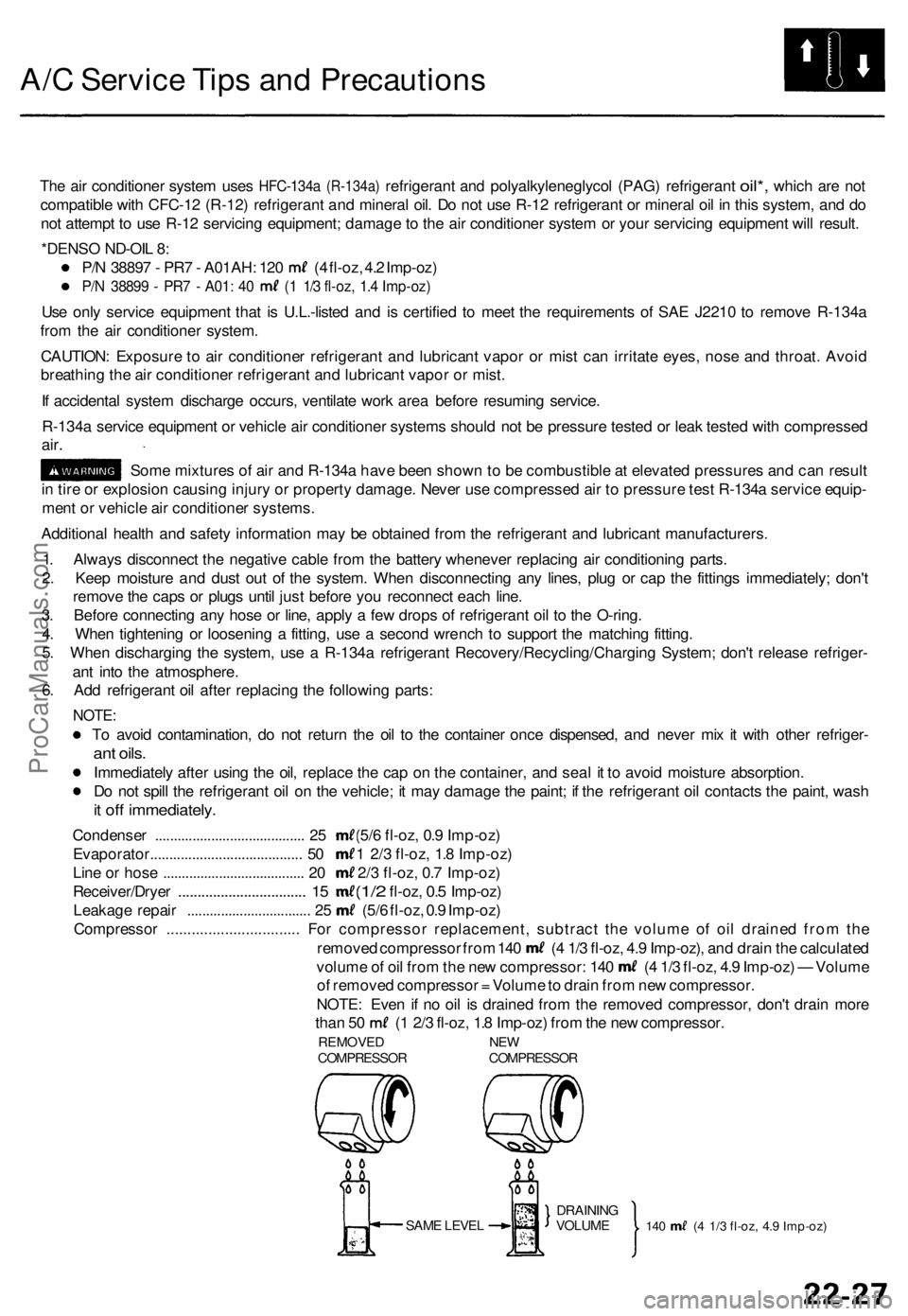
Compressor ................................ For compressor replacement, subtract the volume of oil drained from the
removed compressor from 140 (4 1/3 fl-oz, 4.9 Imp-oz), and drain the calculated
volume of oil from the new compressor: 140 (4 1/3 fl-oz, 4.9 Imp-oz) — Volume
of removed compressor = Volume to drain from new compressor.
NOTE: Even if no oil is drained from the removed compressor, don't drain more
than 50 (1 2/3 fl-oz, 1.8 Imp-oz) from the new compressor.
REMOVED NEW
COMPRESSOR COMPRESSOR
SAME LEVEL
140 (4 1/3 fl-oz, 4.9 Imp-oz)
DRAINING
VOLUMEProCarManuals.com
Page 579 of 1771
Battery
Test
• Batter y flui d (electrolyte ) contain s sulfuri c acid . I t ma y caus e sever e burn s i f i t get s o n you r ski n o r i n you r eyes . Wea r
protectiv e clothin g an d a fac e shield .
I f electrolyt e get s o n you r ski n o r clothes , rins e it of f wit h wate r immediately .
I f electrolyt e get s in you r eyes , flus h it ou t b y splashin g wate r i n you r eye s fo r a t leas t 1 5 minutes ; cal l a physicia n
immediately .
• A batter y give s of f hydroge n gas . I f ignited , th e hydroge n wil l explod e an d coul d crac k th e batter y cas e an d splatte r
aci d o n you . Kee p sparks , flames , an d cigarette s awa y fro m th e battery .
• Overchargin g wil l rais e th e temperatur e o f th e electrolyte . Thi s ma y forc e electrolyt e t o spra y ou t o f th e batter y vents .
Follo w th e charge r manufacturer' s instructions , an d charg e th e batter y a t a prope r rate .
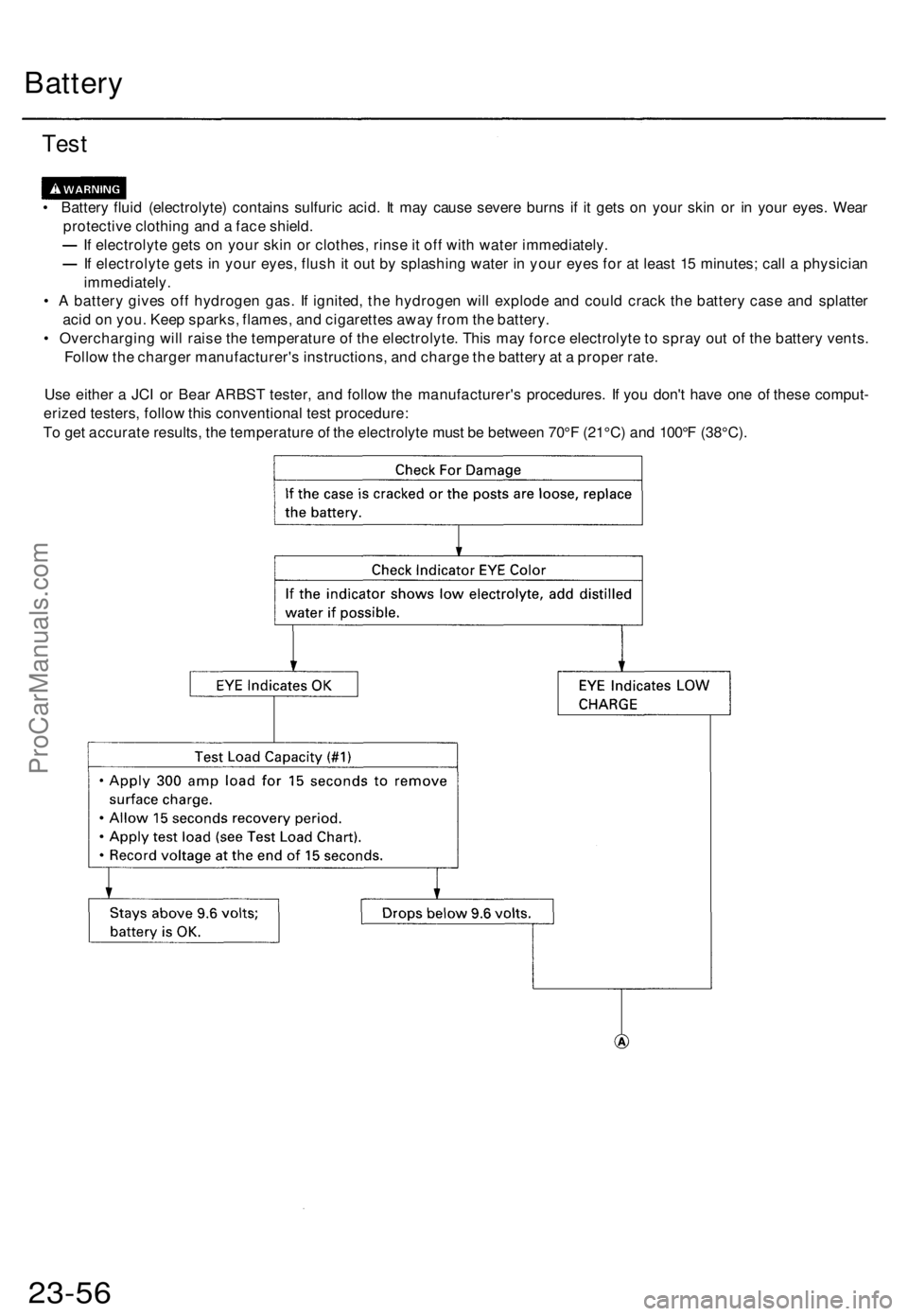
Us e eithe r a JC I o r Bea r ARBS T tester , an d follo w th e manufacturer' s procedures . I f yo u don' t hav e on e o f thes e comput -
erize d testers , follo w thi s conventiona l tes t procedure :
T o ge t accurat e results , th e temperatur e o f th e electrolyt e mus t b e betwee n 70° F (21°C ) an d 100° F (38°C) .
23-56ProCarManuals.com
Page 584 of 1771
Starting Syste m
Starter Tes t
NOTE : Th e ai r temperatur e mus t b e betwee n 5 9 an d
100° F (1 5 an d 38°C ) befor e testing .
Recommende d Procedure :
• Us e a starte r syste m tester .
• Connec t an d operat e th e equipmen t i n accordanc e
wit h th e manufacturer' s instructions .
• Tes t an d troubleshoo t a s described .
Alternat e Procedure :
• Us e followin g equipment :
Ammeter, 0 -40 0 A
Voltmeter , 0 -2 0 V (accurat e withi n 0. 1 volt )
Tachometer , 0 -1,20 0 rp m
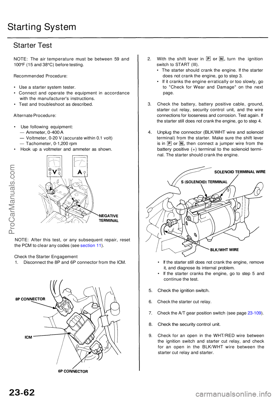
• Hoo k u p a voltmete r an d ammete r a s shown .
NOTE : Afte r thi s test , o r an y subsequen t repair , rese t
th e PC M to clea r an y code s (se e sectio n 11 ).
Chec k th e Starte r Engagemen t
1 . Disconnec t th e 8 P an d 6 P connecto r fro m th e ICM .
2. Wit h th e shif t leve r i n tur n th e ignitio n
switch t o STAR T (III) .
• Th e starte r shoul d cran k th e engine . I f th e starte r
doe s no t cran k th e engine , g o to ste p 3 .
• I f i t crank s th e engin e erraticall y o r to o slowly , g o
t o "Chec k fo r Wea r an d Damage " o n th e nex t
page .
3. Chec k th e battery , batter y positiv e cable , ground ,
starte r cu t relay , securit y contro l unit , an d th e wir e
connection s fo r loosenes s an d corrosion . Tes t again . I f
th e starte r stil l doe s no t cran k th e engine , g o to ste p 4 .
4. Unplu g th e connecto r (BLK/WH T wir e an d solenoi d
terminal ) fro m th e starter . Mak e sur e th e shif t leve r
is i n the n connec t a jumpe r wir e fro m th e
batter y positiv e (+ ) termina l t o th e solenoi d termi -
nal. Th e starte r shoul d cran k th e engine .
• I f th e starte r stil l doe s no t cran k th e engine , remov e
it , an d diagnos e it s interna l problem .
• I f th e starte r crank s th e engine , g o t o ste p 5 an d
continu e th e test .
5. Chec k th e ignitio n switch .
6. Chec k th e starte r cu t relay .
7 . Chec k th e A/ T gea r positio n switc h (se e pag e 23-109 ).
8 . Chec k th e securit y contro l unit .
9. Chec k fo r a n ope n i n th e WHT/RE D wir e betwee n
th e ignitio n switc h an d starte r cu t relay , an d chec k
fo r a n ope n i n th e BLK/WH T wir e betwee n th e
starte r cu t rela y an d starter .
ProCarManuals.com
Page 585 of 1771
Check for Wear and Damage
The starter should crank the engine smoothly and steadily.
If the starter engages, but cranks the engine erratically,
remove it, and inspect the starter drive gear and torque
converter ring gear for damage.
• Check the drive gear overrunning clutch for binding
or slipping when the armature is rotated with the
drive gear held. If the clutch is damaged, replace the
clutch assembly.
Check Cranking Voltage and Current Draw
Cranking voltage should be no less than 8.0 volts.
Current draw should be no more than 450 amperes.
If cranking voltage is too low, or current draw too high,
check for:
Dead or low battery
Open circuit in starter armature commutator segments
Starter armature dragging
Shorted armature winding
Excessive drag in engine
Check Cranking rpm
Engine speed during cranking should be above 100 rpm.
If speed is too low, check for:
Loose battery or starter terminals
Excessively worn starter brushes
Open circuit in commutator segments
Dirty or damaged helical spline or drive gear
Defective drive gear overrunning clutch
Check Starter Disengagement
With the shift lever in or , turn the ignition switch to
"START (III)", and release to "ON (II)". The starter drive
gear should disengage from the flywheel ring gear when
you release the key.
If the drive gear hangs upon the flywheel ring gear, check
for:
• Solenoid plunger and switch malfunction
• Dirty drive gear assembly or damaged overrunning
clutchProCarManuals.com
Page 586 of 1771
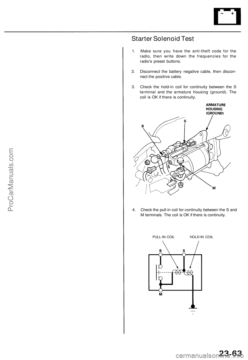
Starter Solenoid Test
1. Make sure you have the anti-theft code for the
radio, then write down the frequencies for the
radio's preset buttons.
2. Disconnect the battery negative cable, then discon-
nect the positive cable.
3. Check the hold-in coil for continuity between the S
terminal and the armature housing (ground). The
coil is OK if there is continuity.
4. Check the pull-in coil for continuity between the S and
M terminals. The coil is OK if there is continuity.
PULL-IN COIL HOLD-IN COILProCarManuals.com
Page 587 of 1771
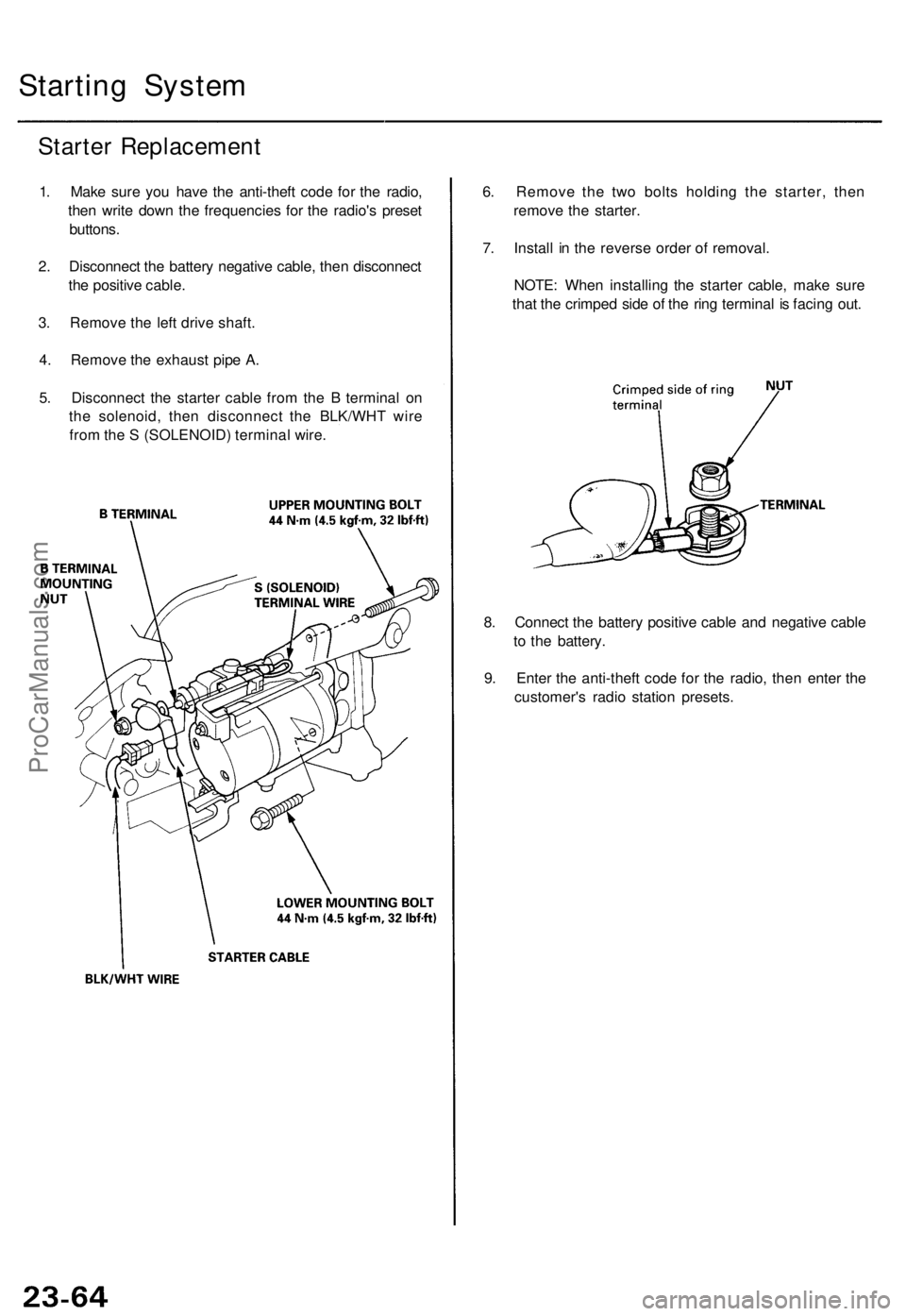
Starting Syste m
Starter Replacemen t
1. Mak e sur e yo u hav e th e anti-thef t cod e fo r th e radio ,
the n writ e dow n th e frequencie s fo r th e radio' s prese t
buttons .
2 . Disconnec t th e batter y negativ e cable , the n disconnec t
th e positiv e cable .
3 . Remov e th e lef t driv e shaft .
4 . Remov e th e exhaus t pip e A .
5 . Disconnec t th e starte r cabl e fro m th e B termina l o n
th e solenoid , the n disconnec t th e BLK/WH T wir e
fro m th e S (SOLENOID ) termina l wire . 6
. Remov e th e tw o bolt s holdin g th e starter , the n
remov e th e starter .
7 . Instal l i n th e revers e orde r o f removal .
NOTE : Whe n installin g th e starte r cable , mak e sur e
tha t th e crimpe d sid e o f th e rin g termina l i s facin g out .
8 . Connec t th e batter y positiv e cabl e an d negativ e cabl e
t o th e battery .
9 . Ente r th e anti-thef t cod e fo r th e radio , the n ente r th e
customer' s radi o statio n presets .
ProCarManuals.com
Page 588 of 1771
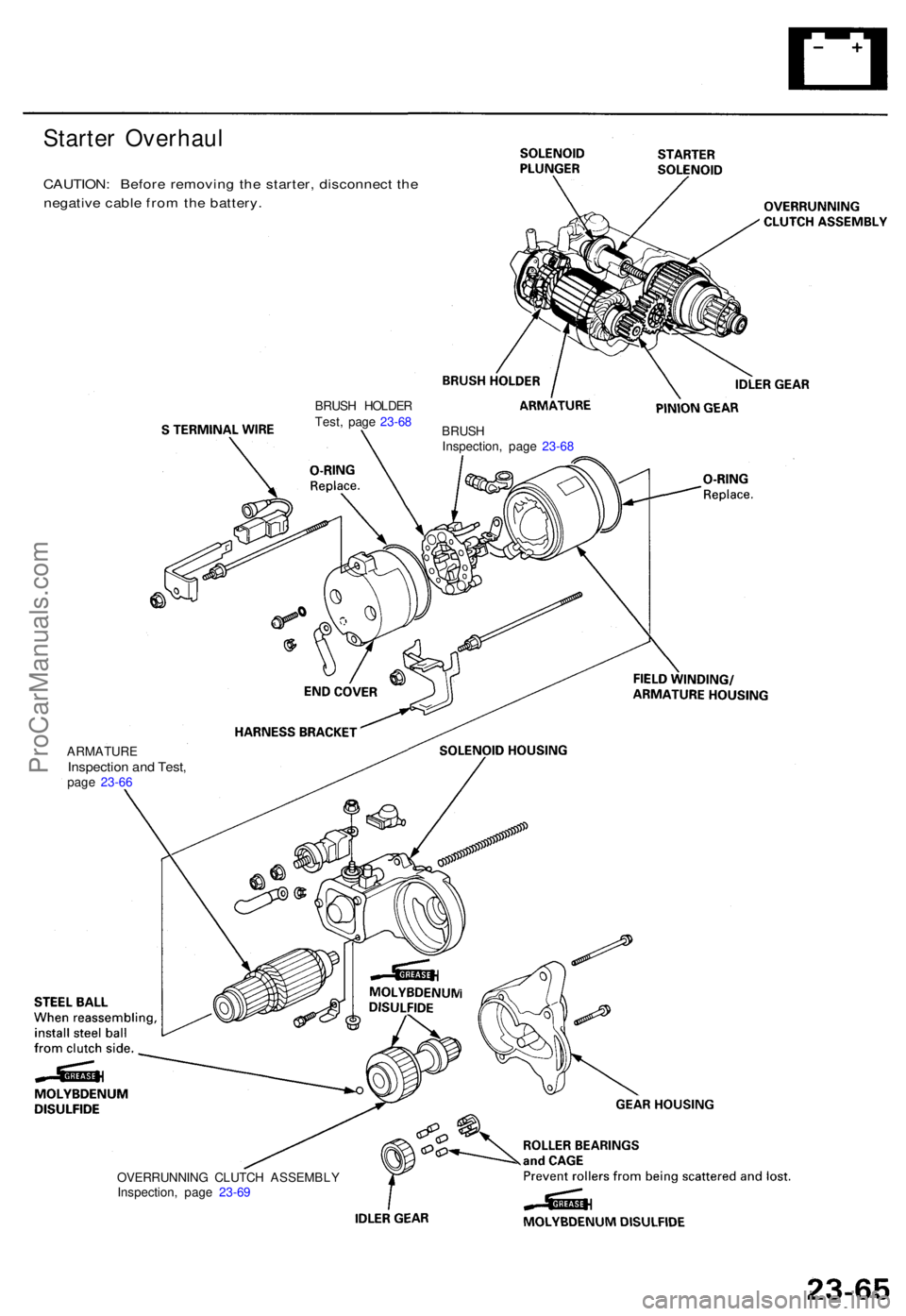
Starter Overhau l
CAUTION: Befor e removin g th e starter , disconnec t th e
negativ e cabl e fro m th e battery .
BRUSH HOLDE R
Test , pag e 23-6 8
BRUSH
Inspection , pag e 23-6 8
OVERRUNNIN G CLUTC H ASSEMBL Y
Inspection , pag e 23-6 9
ARMATUR
E
Inspection an d Test ,page 23-6 6
ProCarManuals.com