Page 1121 of 1771

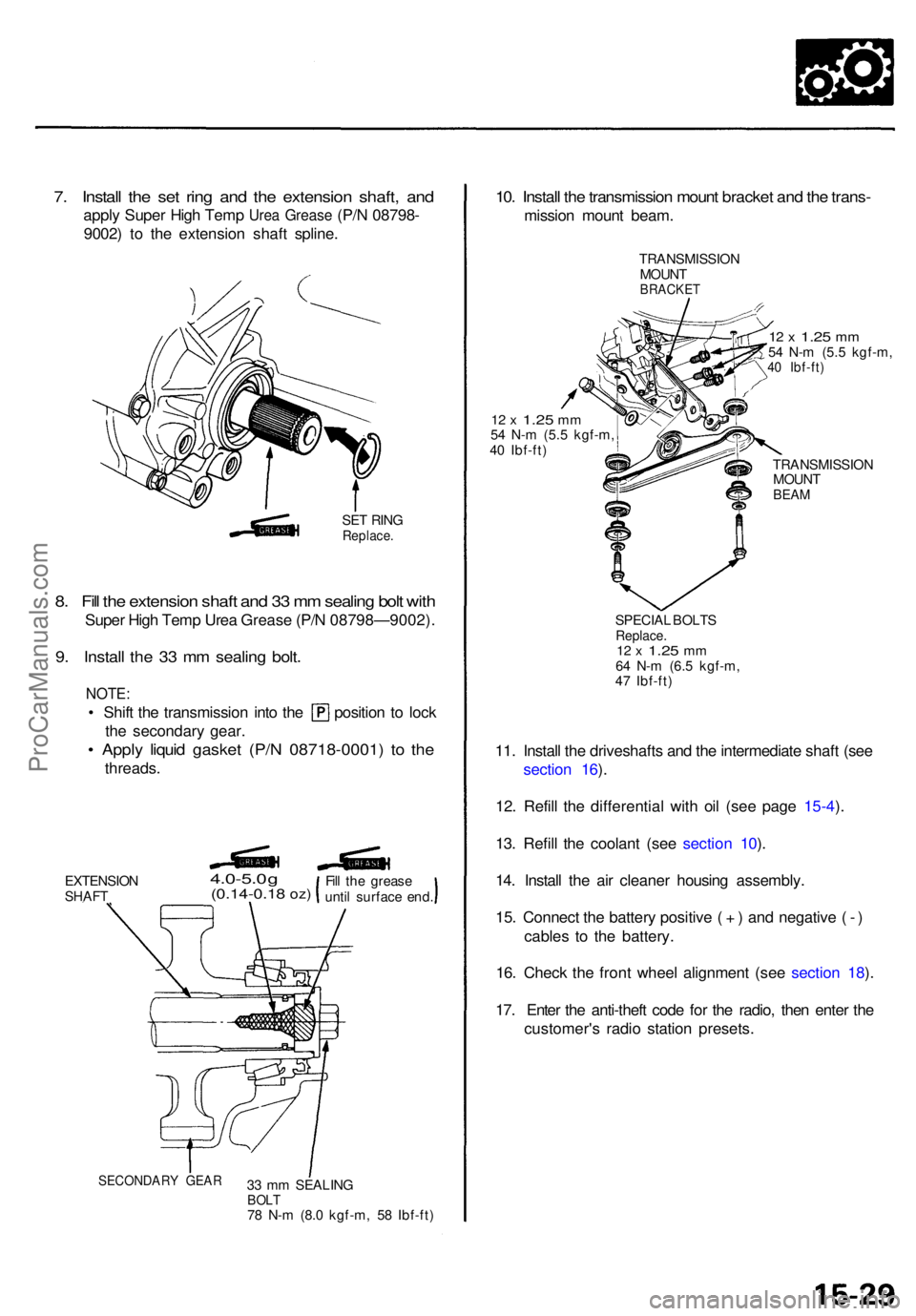
7. Instal l th e se t rin g an d th e extensio n shaft , an d
appl y Supe r Hig h Tem p Urea Greas e (P/N 08798-
9002 ) t o th e extensio n shaf t spline .
SET RIN GReplace .
8. Fil l th e extensio n shaf t an d 3 3 m m sealin g bol t wit h
Supe r Hig h Tem p Ure a Greas e (P/ N 08798—9002) .
9. Instal l th e 3 3 m m sealin g bolt .
NOTE :
• Shif t th e transmissio n int o th e positio n t o loc k
the secondar y gear .
• Appl y liqui d gaske t (P/ N 08718-0001 ) t o th e
threads .
EXTENSIO NSHAFT
4.0-5.0 g(0.14-0.1 8 oz)
33 m m SEALIN GBOLT78 N- m (8. 0 kgf-m , 5 8 Ibf-ft )
10. Instal l th e transmissio n moun t bracke t an d th e trans -
missio n moun t beam .
TRANSMISSIO N
MOUN T
BRACKE T
12 x 1.2 5 mm54 N- m (5. 5 kgf-m ,40 Ibf-ft )
12 x 1.2 5 mm54 N- m (5. 5 kgf-m ,
4 0 Ibf-ft )
TRANSMISSION
MOUN T
BEAM
SPECIA L BOLT SReplace .12 x 1.2 5 mm64 N- m (6. 5 kgf-m ,
4 7 Ibf-ft )
11. Instal l th e driveshaft s an d th e intermediat e shaf t (se e
sectio n 16 ).
12 . Refil l th e differentia l wit h oi l (se e pag e 15-4 ).
13 . Refil l th e coolan t (se e sectio n 10 ).
14 . Instal l th e ai r cleane r housin g assembly .
15 . Connec t th e batter y positiv e ( + ) an d negativ e ( - )
cable s t o th e battery .
16 . Chec k th e fron t whee l alignmen t (se e sectio n 18 ).
17 . Ente r th e anti-thef t cod e fo r th e radio , the n ente r th e
customer' s radi o statio n presets .
SECONDAR Y GEA R
Fill th e greas e
unti l surfac e end .
ProCarManuals.com
Page 1173 of 1771

Steering Whee l
Installatio n (cont'd )
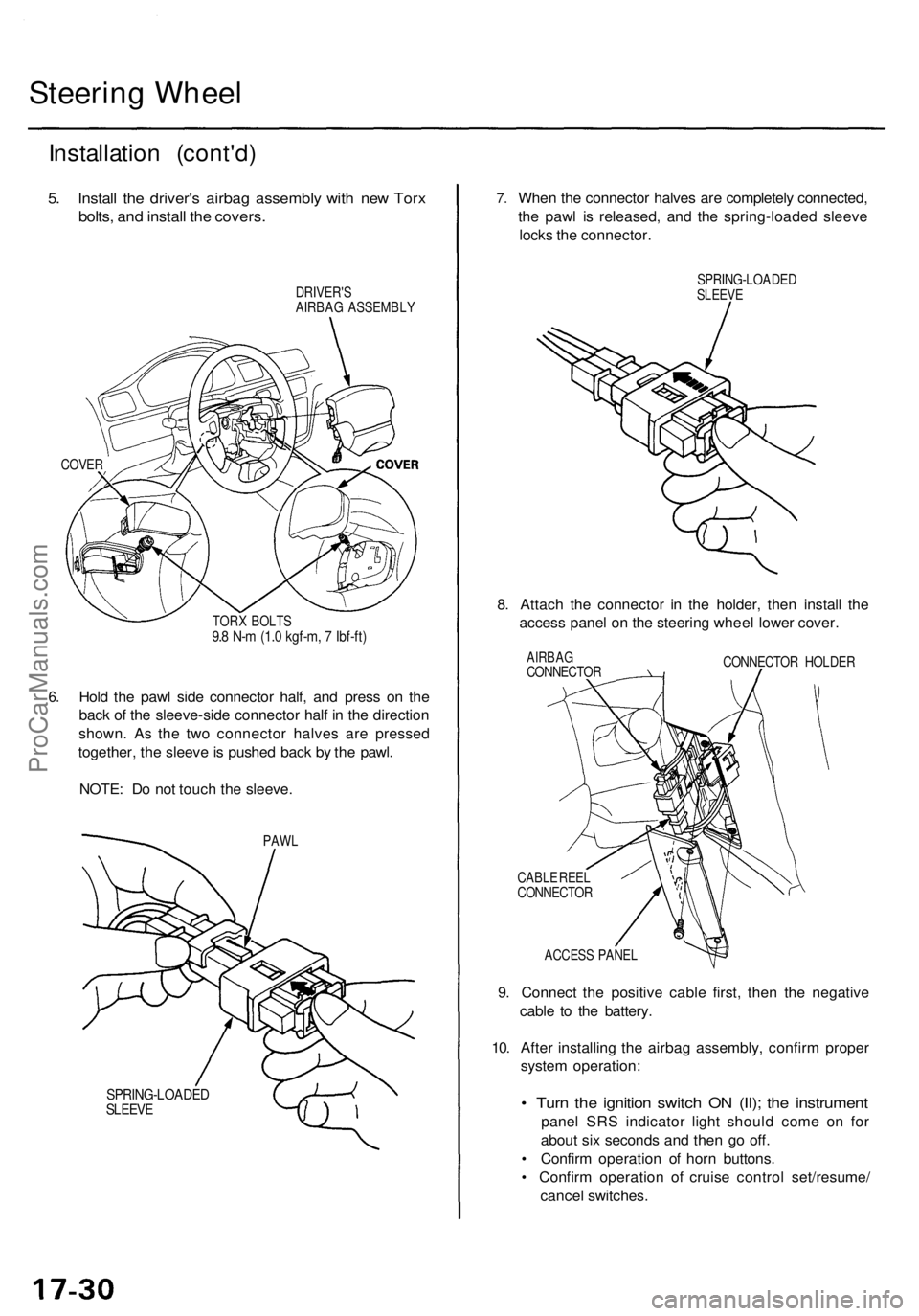
5. Instal l th e driver' s airba g assembl y wit h ne w Tor x
bolts , an d instal l th e covers .
DRIVER' S
AIRBA G ASSEMBL Y
COVER
6.
TOR X BOLT S9.8 N- m (1. 0 kgf-m , 7 Ibf-ft )
Hold th e paw l sid e connecto r half , an d pres s o n th e
bac k o f th e sleeve-sid e connecto r hal f i n th e directio n
shown . A s th e tw o connecto r halve s ar e presse d
together , th e sleev e is pushe d bac k b y th e pawl .
NOTE : D o no t touc h th e sleeve .
PAWL
SPRING-LOADE DSLEEVE
7.Whe n th e connecto r halve s ar e completel y connected ,
th e paw l i s released , an d th e spring-loade d sleev e
lock s th e connector .
SPRING-LOADE DSLEEVE
8. Attac h th e connecto r i n th e holder , the n instal l th e
acces s pane l o n th e steerin g whee l lowe r cover .
AIRBA GCONNECTO R CONNECTO
R HOLDE R
CABL E REE L
CONNECTO R
ACCES S PANE L
9. Connect the positiv e cabl e first , the n th e negativ e
cabl e t o th e battery .
10 . Afte r installin g th e airba g assembly , confir m prope r
syste m operation :
• Tur n th e ignitio n switc h O N (II) ; th e instrumen t
panel SR S indicato r ligh t shoul d com e o n fo r
abou t si x second s an d the n g o off .
• Confir m operatio n o f hor n buttons .
• Confir m operatio n o f cruis e contro l set/resume /
cance l switches .
ProCarManuals.com
Page 1296 of 1771
GAUGE ASSEMBLY
UNDER-HOOD FUSE/RELAY BOX
ABS INDICATOR LIGHT
BATTERY
(100 A) FUSE
IG (50 A) FUSE
STOP/ HORN
(20 A) FUSE
UNDER-DASH FUSE/RELAY BOX
UNDER-HOOD ABS FUSE/RELAY BOX
HEATER
CONTROL RELAY
(7.5 A) FUSE
BACK-UP LIGHTS/
METER LIGHTS
(SUN ROOF)
(10 A) FUSE
ECU (ECM)/
CRUISE CONTROL/
EAT ECU
(15 A) FUSE
ABS MOTOR (40 A) FUSE
ABS B1 (20 A) FUSE
ABS B2 (15 A) FUSE
ABS PUMP MOTOR RELAY
UNDER-DASH RELAY BOX
ABS UNIT (10 A) FUSE
REAR FAIL-SAFE RELAY
FRONT FAIL-SAFE RELAYProCarManuals.com
Page 1322 of 1771
ABS INDICATOR LIGHT
BATTERY
(100 A) FUSE
STOP/ HORN
(20 A) FUSE
IG (50 A) FUSE
UNDER-DASH FUSE/RELAY BOX
UNDER-HOOD ABS FUSE/RELAY BOX
HEATER
CONTROL RELAY
(7.5 A) FUSE
BACK-UP LIGHTS/
METER LIGHTS
(SUN ROOF)
(10 A) FUSE
ECU (ECM)/
CRUISE CONTROL/
EAT ECU
(15 A) FUSE
ABS MOTOR (30 A) FUSE
ABS B1 (20 A) FUSE
UNDER-DASH RELAY BOX
ABS PUMP MOTOR RELAY
ABS UNIT (7.5 A) FUSE
FAIL-SAFE RELAYProCarManuals.com
Page 1327 of 1771
ABS Control Unit Terminal Arrangement
ABS CONTROL UNIT 22P CONNECTOR
Wire side of female terminals
VB: Battery VoltageProCarManuals.com
Page 1328 of 1771
VB: Battery VoltageProCarManuals.com
Page 1329 of 1771
ABS Control Unit Terminal Arrangement
ABS CONTROL UNIT 12P CONNECTOR
Wire side of female terminals
VB: Battery VoltageProCarManuals.com
Page 1330 of 1771

Troubleshooting Precautions
ABS Indicator Light
1. If the system is OK, the ABS indicator light goes off two seconds after turning the ignition switch ON (II) without start-
ing the engine. After starting the engine, the ABS indicator light comes on again and goes off after two seconds. This
occurs because the ABS control unit is activated by the IG2 power source.
2. The ABS indicator light comes on when the ABS control unit detects a problem in the system. However, even though
the system is normal, the ABS indicator light comes on, too, under the following conditions. To determine the actual
cause of problem, question the customer about the problem, talking the following conditions into consideration.
Only drive wheels rotate
One wheel stuck of drive wheels
Vehicle spin
ABS operate condition continue for long time
Signal disturbance
3. When a problem is detected and the ABS indicator light comes on, there are cases when the indicator light stays on
until the ignition switch is turned OFF, and cases when the indicator light goes off automatically when the system
returns normal. For the DTC 61 and 62, the indicator light goes off automatically when the system returns normal. For
all other codes, the indicator light stays on until the ignition switch is turned OFF.
4. For DTCs 12, 14, 16, 18, 21, 22, 23, 24, 51, 52 and 53, the indicator light goes off when the vehicle is driven again and
the signals are OK after the ignition switch is turned from OFF to ON (II). However, if the DTC is erased, the CPU is
reset and the indicator light goes off right after the engine is started if the signals are OK.
Diagnostic Trouble Code (DTC)
1. The DTC is not memorized if the CPU cannot be activated or the CPU fails and the indicator light comes on.
2. The memory can hold any number of DTCs. However, when the same DTC is detected more than once, the later one
is written over the old one. Therefore, when the same problem is detected repeatedly, it is memorized as one DTC.
3. The DTCs are indicated in the order of ascending number, not in the order they occur.
4. The DTCs are memorized in the EEPROM (non-volatile memory). Therefore, the memorized DTCs cannot be canceled
by disconnecting the battery. Perform the specified procedures to erase the DTCs.
Self-diagnosis
1. The self-diagnosis can be classified into two categories.
Initial diagnosis: Performed right after the engine starts and until the ABS indicator light goes off.
Regular diagnosis: Performed right after the initial diagnosis until the ignition switch is turned OFF.
2. When a problem is detected by self-diagnosis, the system
Turns the ABS indicator light ON
Memorizes the DTC
Turns the fail-safe relay OFF
Stops ABS controlProCarManuals.com