1995 ACURA TL reset
[x] Cancel search: resetPage 876 of 1771
How to Read Flowcharts
A flowchart is designed to be used from start to final repair. It's like a map showing you the shortest distance. But beware:
If you go off the "map" anywhere but a "stop" symbol, you can easily get lost.
Describes the conditions or situation to start a troubleshooting flowchart.
Asks you to do something; perform a test, set up a condition etc.
Asks you about the result of an action, then sends you in the appropriate troubleshooting direction.
The end of a series of actions and decisions, describes a final repair action and sometimes directs you to
an earlier part of the flowchart to confirm your repair.
NOTE:
The term "Intermittent Failure" is used in these charts. It simply means a system may have had a failure, but it checks
out OK at this time. If the Malfunction Indicator Lamp (MIL) on the dash does not come on, check for poor connections
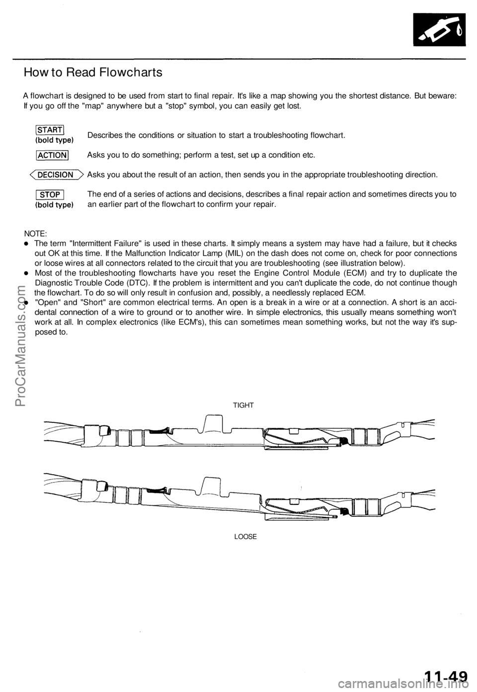
or loose wires at all connectors related to the circuit that you are troubleshooting (see illustration below).
Most of the troubleshooting flowcharts have you reset the Engine Control Module (ECM) and try to duplicate the
Diagnostic Trouble Code (DTC). If the problem is intermittent and you can't duplicate the code, do not continue though
the flowchart. To do so will only result in confusion and, possibly, a needlessly replaced ECM.
"Open" and "Short" are common electrical terms. An open is a break in a wire or at a connection. A short is an acci-
dental connection of a wire to ground or to another wire. In simple electronics, this usually means something won't
work at all. In complex electronics (like ECM's), this can sometimes mean something works, but not the way it's sup-
posed to.
TIGHT
LOOSEProCarManuals.com
Page 910 of 1771
Fuel Filte r
Replacemen t
Do no t smok e whil e workin g o n fue l system .
Kee p ope n flam e awa y fro m you r wor k area .
• Whil e replacin g th e fue l filter , b e carefu l t o kee p a saf e
distanc e betwee n batter y terminal s an d an y tools .
Th e fue l filte r shoul d b e replace d wheneve r th e fue l pres -
sur e drop s belo w th e specifie d valu e [29 4 - 34 3 kPa ,
3. 0 - 3. 5 kgf/cm
2, 4 3 - 5 0 ps i wit h th e fue l pressur e regula -
to r vacuu m hos e disconnecte d an d pinched ] afte r makin g
sur e tha t th e fue l pum p an d th e fue l pressur e regulato r
are OK .
1. Mak e sur e yo u hav e th e anti-thef t cod e fo r th e radio ,
the n writ e dow n th e frequencie s fo r th e radio' s pre -
set buttons .
2. Disconnec t th e batter y negativ e cabl e fro m th e bat -
ter y negativ e terminal .
3 . Plac e a sho p towe l unde r an d aroun d th e fue l filter .
4 . Reliev e fue l pressur e (se e pag e 11-124 ).
5 . Remov e th e banj o bol t (model s wit h servic e bolt ) o r
1 2 m m banj o bol t (model s withou t servic e bolt ) an d
th e fue l fee d pip e whil e supportin g th e fue l filte r
wit h anothe r wrench , a s shown .
6 . Remov e th e fue l filte r clam p an d fue l filter .
7 . Instal l th e ne w fue l filte r i n th e revers e orde r of
removal , an d not e thes e items :
• Whe n assembling , us e ne w washer s a s shown .
• Clea n th e flare d join t o f hig h pressur e hose s
thoroughl y befor e reconnectin g them .
8 . Ente r th e anti-thef t cod e fo r th e radio , the n ente r th e
customer' s radi o statio n presets .
ProCarManuals.com
Page 975 of 1771

Troubleshooting Procedures
Checking the Diagnostic Trouble Code (DTC)
with an OBD II Scan tool or Honda PGM Tester
When the TCM senses an abnormality in the input or output systems, the indicator light in the gauge assembly will
blink. When the 16P Data Link Connector (DLC) (located behind the ashtray) is connected to the OBD II Scan Tool or Honda
PGM Tester as shown, the scan tool or tester will indicate the Diagnostic Trouble Code (DTC) when the ignition switch is
turned ON(II).
When the indicator light has been reported on, connect the OBD II Scan Tool conforming to SAE J1978 or Honda PGM
Tester to the DLC (16P) behind the ashtray. Turn the ignition switch on (II), and observe the DTC on the screen of the OBD II
Scan Tool or Honda PGM Tester. After determining the DTC, refer to the electrical system Symptom-to-Component Chart
on page 14-56 and 14-57.
NOTE: See the OBD II Scan Tool or Honda PGM Tester user's manual for specific instruction.
OBD II SCAN TOOL or
HONDA PGM TESTER
Some PGM-FI problems will also make the indicator light come on. After repairing the PGM-FI system, disconnect the
BACK UP RADIO fuse (10 A) in the under-hood fuse/relay box for more than 10 seconds to reset the TCM memory, then
retest.
NOTE: Disconnecting the BACK UP RADIO fuse also cancels the radio anti-theft code, preset stations and the clock setting.
Get the customer's code number, and make note of the radio presets before removing the fuse so you can reset them.
DATA LINK CONNECTOR (16P)ProCarManuals.com
Page 976 of 1771
Checking th e Diagnosti c Troubl e Cod e (DTC )
wit h th e Servic e Chec k Connecto r an d Specia l Too l
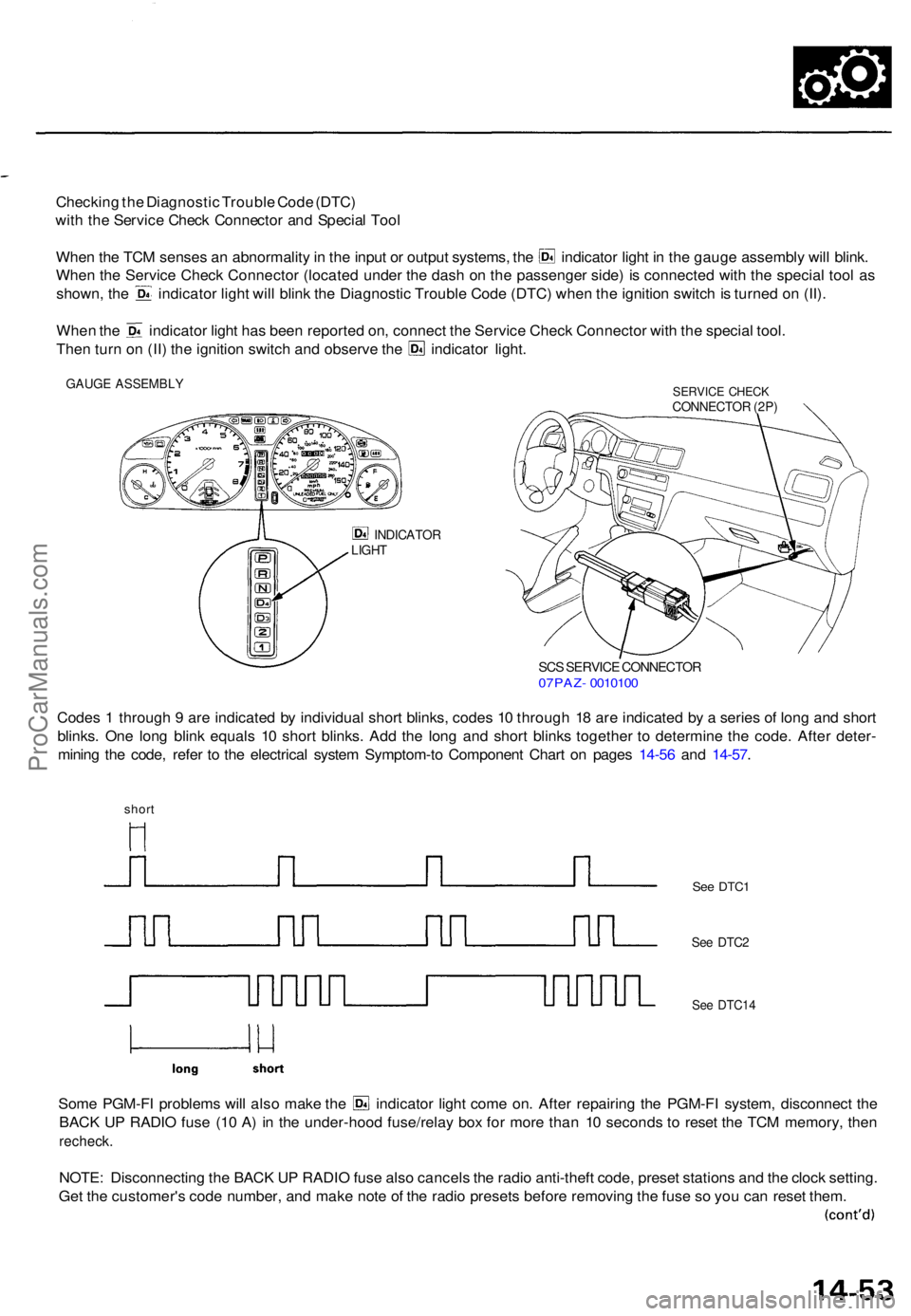
Whe n th e TC M sense s a n abnormalit y in th e inpu t o r outpu t systems , th e indicato r ligh t i n th e gaug e assembl y wil l blink .
Whe n th e Servic e Chec k Connecto r (locate d unde r th e das h o n th e passenge r side ) i s connecte d wit h th e specia l too l a s
shown , th e indicato r ligh t wil l blin k th e Diagnosti c Troubl e Cod e (DTC ) whe n th e ignitio n switc h is turne d o n (II) .
Whe n th e indicato r ligh t ha s bee n reporte d on , connec t th e Servic e Chec k Connecto r wit h th e specia l tool .
Then tur n o n (II ) th e ignitio n switc h an d observ e th e indicato r light .
GAUG E ASSEMBL YSERVICE CHEC KCONNECTO R (2P )
INDICATO RLIGHT
SCS SERVIC E CONNECTO R07PAZ- 001010 0
Codes 1 throug h 9 ar e indicate d b y individua l shor t blinks , code s 1 0 throug h 1 8 ar e indicate d b y a serie s o f lon g an d shor t
blinks . On e lon g blin k equal s 1 0 shor t blinks . Ad d th e lon g an d shor t blink s togethe r t o determin e th e code . Afte r deter -
minin g th e code , refe r t o th e electrica l syste m Symptom-t o Componen t Char t o n page s 14-5 6 an d 14-57 .
short
Some PGM-F I problem s wil l als o mak e th e indicato r ligh t com e on . Afte r repairin g th e PGM-F I system , disconnec t th e
BAC K U P RADI O fus e (1 0 A ) i n th e under-hoo d fuse/rela y bo x fo r mor e tha n 1 0 second s t o rese t th e TC M memory , the n
recheck .
NOTE: Disconnectin g th e BAC K U P RADI O fus e als o cancel s th e radi o anti-theft code, prese t station s an d th e cloc k setting .
Ge t th e customer' s cod e number , an d mak e not e o f th e radi o preset s befor e removin g th e fus e s o yo u ca n rese t them .
See DTC 1
See DTC 2
See DTC1 4
ProCarManuals.com
Page 978 of 1771

4. Inspec t th e circui t o n th e TC M accordin g t o th e trou -
bleshootin g flowchar t wit h th e specia l tool s an d a
digita l multimete r a s shown .
How to us e th e Backprob e Se t
Connec t th e backprob e adapter s t o th e stackin g patc h
cords , an d connec t th e cord s t o a multimeter . Usin g
th e wir e insulatio n a s a guid e fo r th e contoure d ti p o f
the backprob e adapter , gentl y slid e th e ti p int o th e
connecto r fro m th e wir e sid e unti l i t come s i n contac t
with th e termina l en d o f th e wire .
BACKPROB E SE T07SAZ-001000 A
(tw o required )
BACKPROB EADAPTER
STACKIN GPATCH COR D
TCM
DIGITA L MULTIMETE R
(Commerciall y available )
KS-AHM-32-003 ,or equivalen t
TCM Rese t Procedur e
1 . Mak e sur e yo u hav e th e anti-thef t cod e fo r th e radio ,
the n writ e dow n th e frequencie s fo r th e radio' s pre -
set buttons .
2. Tur n th e ignitio n switc h OFF .
3 . Remov e th e No . 3 9 BAC K U P RADI O fus e (1 0 A )
fro m th e under-hoo d fuse/rela y bo x fo r 1 0 second s
t o rese t th e TCM .
NOTE : Th e TC M memor y canno t b e cleare d b y
usin g th e OB D II Sca n Too l o r Hond a PG M Tester ; b e
sur e to remov e th e BAC K U P RADI O fus e to rese t th e
TCM .
BACK U P RADI O
(1 0 A ) FUS E
UNDER-HOO D
FUSE/RELAYBOX
Fina l Procedur e
NOTE : Thi s procedur e mus t b e don e afte r an y trouble -
shooting.
1. Tur n th e ignitio n switc h OFF .
2 . Disconnec t th e OB D II Sca n Too l o r Hond a PG M
Teste r fro m th e Dat a Lin k Connector , o r remov e th e
specia l too l fro m th e Servic e Chec k Connector .
3. Rese t th e TCM .
4. Tur n th e ignitio n switc h O N (II) .
5 . Ente r th e anti-thef t cod e fo r th e radio , the n ente r th e
customer' s radi o statio n presets .
ProCarManuals.com
Page 1084 of 1771
Transmission
Installation (cont'd )
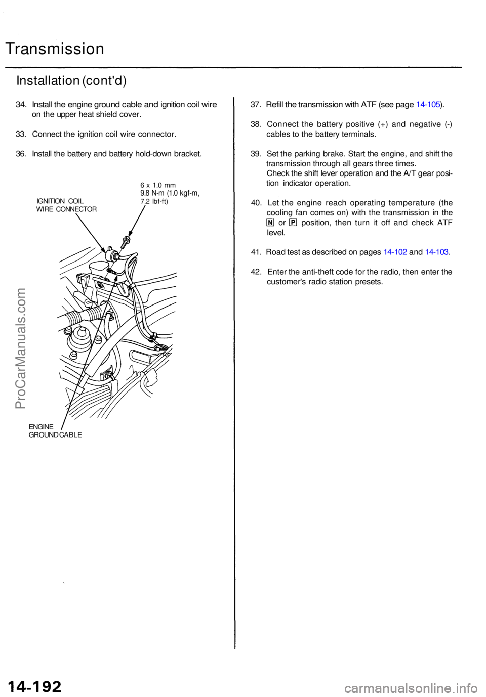
34. Instal l th e engin e groun d cabl e an d ignitio n coi l wir e
on th e uppe r hea t shiel d cover .
33 . Connec t th e ignitio n coi l wir e connector .
36 . Instal l th e batter y an d batter y hold-dow n bracket .
IGNITION COI LWIRE CONNECTO R
6 x 1. 0 m m9.8 N- m (1. 0 kgf-m ,7.2 Ibf-ft )
ENGIN EGROUN D CABL E
37. Refil l th e transmissio n wit h AT F (se e pag e 14-105 ).
38 . Connec t th e batter y positiv e (+ ) an d negativ e (- )
cable s t o th e batter y terminals .
39 . Se t th e parkin g brake . Star t th e engine , an d shif t th e
transmissio n throug h al l gear s thre e times .
Chec k th e shif t leve r operatio n an d th e A/ T gea r posi -
tio n indicato r operation .
40 . Le t th e engin e reac h operatin g temperatur e (th e
coolin g fa n come s on ) wit h th e transmissio n i n th e
or position , the n tur n i t of f an d chec k AT F
level .
41. Roa d tes t a s describe d o n page s 14-10 2 an d 14-103 .
42 . Ente r th e anti-thef t cod e fo r th e radio , the n ente r th e
customer' s radi o statio n presets .
ProCarManuals.com
Page 1121 of 1771
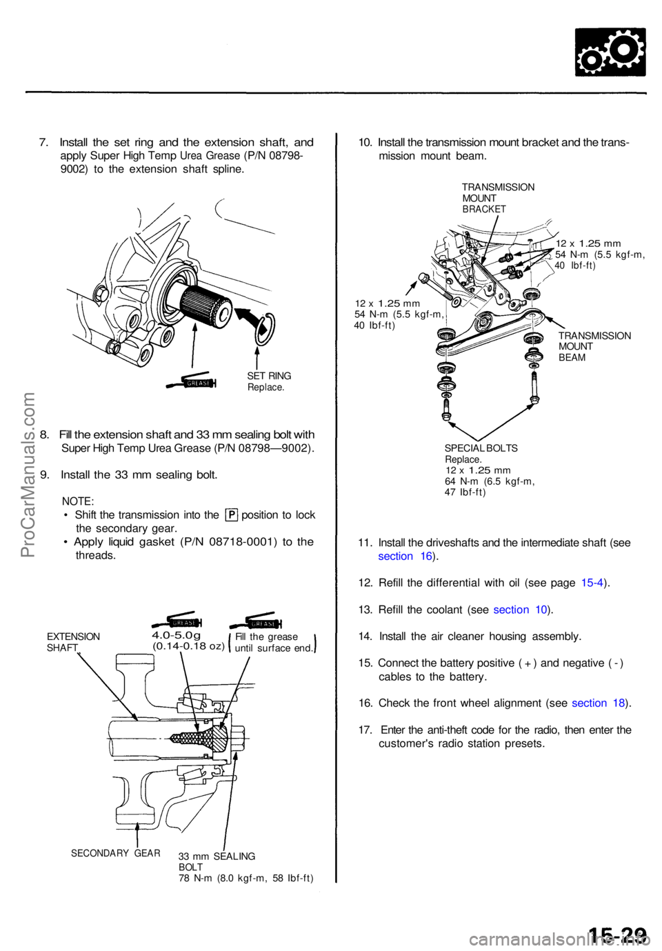
7. Instal l th e se t rin g an d th e extensio n shaft , an d
appl y Supe r Hig h Tem p Urea Greas e (P/N 08798-
9002 ) t o th e extensio n shaf t spline .
SET RIN GReplace .
8. Fil l th e extensio n shaf t an d 3 3 m m sealin g bol t wit h
Supe r Hig h Tem p Ure a Greas e (P/ N 08798—9002) .
9. Instal l th e 3 3 m m sealin g bolt .
NOTE :
• Shif t th e transmissio n int o th e positio n t o loc k
the secondar y gear .
• Appl y liqui d gaske t (P/ N 08718-0001 ) t o th e
threads .
EXTENSIO NSHAFT
4.0-5.0 g(0.14-0.1 8 oz)
33 m m SEALIN GBOLT78 N- m (8. 0 kgf-m , 5 8 Ibf-ft )
10. Instal l th e transmissio n moun t bracke t an d th e trans -
missio n moun t beam .
TRANSMISSIO N
MOUN T
BRACKE T
12 x 1.2 5 mm54 N- m (5. 5 kgf-m ,40 Ibf-ft )
12 x 1.2 5 mm54 N- m (5. 5 kgf-m ,
4 0 Ibf-ft )
TRANSMISSION
MOUN T
BEAM
SPECIA L BOLT SReplace .12 x 1.2 5 mm64 N- m (6. 5 kgf-m ,
4 7 Ibf-ft )
11. Instal l th e driveshaft s an d th e intermediat e shaf t (se e
sectio n 16 ).
12 . Refil l th e differentia l wit h oi l (se e pag e 15-4 ).
13 . Refil l th e coolan t (se e sectio n 10 ).
14 . Instal l th e ai r cleane r housin g assembly .
15 . Connec t th e batter y positiv e ( + ) an d negativ e ( - )
cable s t o th e battery .
16 . Chec k th e fron t whee l alignmen t (se e sectio n 18 ).
17 . Ente r th e anti-thef t cod e fo r th e radio , the n ente r th e
customer' s radi o statio n presets .
SECONDAR Y GEA R
Fill th e greas e
unti l surfac e end .
ProCarManuals.com
Page 1330 of 1771
Troubleshooting Precautions
ABS Indicator Light
1. If the system is OK, the ABS indicator light goes off two seconds after turning the ignition switch ON (II) without start-
ing the engine. After starting the engine, the ABS indicator light comes on again and goes off after two seconds. This
occurs because the ABS control unit is activated by the IG2 power source.
2. The ABS indicator light comes on when the ABS control unit detects a problem in the system. However, even though
the system is normal, the ABS indicator light comes on, too, under the following conditions. To determine the actual
cause of problem, question the customer about the problem, talking the following conditions into consideration.
Only drive wheels rotate
One wheel stuck of drive wheels
Vehicle spin
ABS operate condition continue for long time
Signal disturbance
3. When a problem is detected and the ABS indicator light comes on, there are cases when the indicator light stays on
until the ignition switch is turned OFF, and cases when the indicator light goes off automatically when the system
returns normal. For the DTC 61 and 62, the indicator light goes off automatically when the system returns normal. For
all other codes, the indicator light stays on until the ignition switch is turned OFF.
4. For DTCs 12, 14, 16, 18, 21, 22, 23, 24, 51, 52 and 53, the indicator light goes off when the vehicle is driven again and
the signals are OK after the ignition switch is turned from OFF to ON (II). However, if the DTC is erased, the CPU is
reset and the indicator light goes off right after the engine is started if the signals are OK.
Diagnostic Trouble Code (DTC)
1. The DTC is not memorized if the CPU cannot be activated or the CPU fails and the indicator light comes on.
2. The memory can hold any number of DTCs. However, when the same DTC is detected more than once, the later one
is written over the old one. Therefore, when the same problem is detected repeatedly, it is memorized as one DTC.
3. The DTCs are indicated in the order of ascending number, not in the order they occur.
4. The DTCs are memorized in the EEPROM (non-volatile memory). Therefore, the memorized DTCs cannot be canceled
by disconnecting the battery. Perform the specified procedures to erase the DTCs.
Self-diagnosis
1. The self-diagnosis can be classified into two categories.
Initial diagnosis: Performed right after the engine starts and until the ABS indicator light goes off.
Regular diagnosis: Performed right after the initial diagnosis until the ignition switch is turned OFF.
2. When a problem is detected by self-diagnosis, the system
Turns the ABS indicator light ON
Memorizes the DTC
Turns the fail-safe relay OFF
Stops ABS controlProCarManuals.com